EP0414518B1 - Support d'enregistrement optique, méthode associée et appareil pour enregistrer et en reproduire de l'information - Google Patents
Support d'enregistrement optique, méthode associée et appareil pour enregistrer et en reproduire de l'information Download PDFInfo
- Publication number
- EP0414518B1 EP0414518B1 EP90309197A EP90309197A EP0414518B1 EP 0414518 B1 EP0414518 B1 EP 0414518B1 EP 90309197 A EP90309197 A EP 90309197A EP 90309197 A EP90309197 A EP 90309197A EP 0414518 B1 EP0414518 B1 EP 0414518B1
- Authority
- EP
- European Patent Office
- Prior art keywords
- recording
- signals
- offset
- recorded
- data
- Prior art date
- Legal status (The legal status is an assumption and is not a legal conclusion. Google has not performed a legal analysis and makes no representation as to the accuracy of the status listed.)
- Expired - Lifetime
Links
- 230000003287 optical effect Effects 0.000 title claims abstract description 35
- 238000000034 method Methods 0.000 title claims description 25
- 238000001514 detection method Methods 0.000 description 14
- 230000007704 transition Effects 0.000 description 13
- 230000001172 regenerating effect Effects 0.000 description 6
- 230000010287 polarization Effects 0.000 description 4
- 230000001360 synchronised effect Effects 0.000 description 4
- 238000010586 diagram Methods 0.000 description 3
- 230000000694 effects Effects 0.000 description 3
- 238000000605 extraction Methods 0.000 description 2
- 230000002411 adverse Effects 0.000 description 1
- 230000004075 alteration Effects 0.000 description 1
- 230000001934 delay Effects 0.000 description 1
- 230000003111 delayed effect Effects 0.000 description 1
- 238000004519 manufacturing process Methods 0.000 description 1
- 230000010355 oscillation Effects 0.000 description 1
- 230000006641 stabilisation Effects 0.000 description 1
- 238000011105 stabilization Methods 0.000 description 1
Images


Classifications
-
- G—PHYSICS
- G11—INFORMATION STORAGE
- G11B—INFORMATION STORAGE BASED ON RELATIVE MOVEMENT BETWEEN RECORD CARRIER AND TRANSDUCER
- G11B27/00—Editing; Indexing; Addressing; Timing or synchronising; Monitoring; Measuring tape travel
- G11B27/10—Indexing; Addressing; Timing or synchronising; Measuring tape travel
- G11B27/19—Indexing; Addressing; Timing or synchronising; Measuring tape travel by using information detectable on the record carrier
- G11B27/24—Indexing; Addressing; Timing or synchronising; Measuring tape travel by using information detectable on the record carrier by sensing features on the record carrier other than the transducing track ; sensing signals or marks recorded by another method than the main recording
-
- G—PHYSICS
- G11—INFORMATION STORAGE
- G11B—INFORMATION STORAGE BASED ON RELATIVE MOVEMENT BETWEEN RECORD CARRIER AND TRANSDUCER
- G11B20/00—Signal processing not specific to the method of recording or reproducing; Circuits therefor
- G11B20/10—Digital recording or reproducing
- G11B20/12—Formatting, e.g. arrangement of data block or words on the record carriers
- G11B20/1217—Formatting, e.g. arrangement of data block or words on the record carriers on discs
- G11B20/1251—Formatting, e.g. arrangement of data block or words on the record carriers on discs for continuous data, e.g. digitised analog information signals, pulse code modulated [PCM] data
-
- G—PHYSICS
- G11—INFORMATION STORAGE
- G11B—INFORMATION STORAGE BASED ON RELATIVE MOVEMENT BETWEEN RECORD CARRIER AND TRANSDUCER
- G11B27/00—Editing; Indexing; Addressing; Timing or synchronising; Monitoring; Measuring tape travel
- G11B27/10—Indexing; Addressing; Timing or synchronising; Measuring tape travel
- G11B27/19—Indexing; Addressing; Timing or synchronising; Measuring tape travel by using information detectable on the record carrier
- G11B27/28—Indexing; Addressing; Timing or synchronising; Measuring tape travel by using information detectable on the record carrier by using information signals recorded by the same method as the main recording
- G11B27/30—Indexing; Addressing; Timing or synchronising; Measuring tape travel by using information detectable on the record carrier by using information signals recorded by the same method as the main recording on the same track as the main recording
- G11B27/3027—Indexing; Addressing; Timing or synchronising; Measuring tape travel by using information detectable on the record carrier by using information signals recorded by the same method as the main recording on the same track as the main recording used signal is digitally coded
-
- G—PHYSICS
- G11—INFORMATION STORAGE
- G11B—INFORMATION STORAGE BASED ON RELATIVE MOVEMENT BETWEEN RECORD CARRIER AND TRANSDUCER
- G11B7/00—Recording or reproducing by optical means, e.g. recording using a thermal beam of optical radiation by modifying optical properties or the physical structure, reproducing using an optical beam at lower power by sensing optical properties; Record carriers therefor
- G11B7/004—Recording, reproducing or erasing methods; Read, write or erase circuits therefor
-
- G—PHYSICS
- G11—INFORMATION STORAGE
- G11B—INFORMATION STORAGE BASED ON RELATIVE MOVEMENT BETWEEN RECORD CARRIER AND TRANSDUCER
- G11B7/00—Recording or reproducing by optical means, e.g. recording using a thermal beam of optical radiation by modifying optical properties or the physical structure, reproducing using an optical beam at lower power by sensing optical properties; Record carriers therefor
- G11B7/007—Arrangement of the information on the record carrier, e.g. form of tracks, actual track shape, e.g. wobbled, or cross-section, e.g. v-shaped; Sequential information structures, e.g. sectoring or header formats within a track
- G11B7/0079—Zoned data area, e.g. having different data structures or formats for the user data within data layer, Zone Constant Linear Velocity [ZCLV], Zone Constant Angular Velocity [ZCAV], carriers with RAM and ROM areas
-
- G—PHYSICS
- G11—INFORMATION STORAGE
- G11B—INFORMATION STORAGE BASED ON RELATIVE MOVEMENT BETWEEN RECORD CARRIER AND TRANSDUCER
- G11B7/00—Recording or reproducing by optical means, e.g. recording using a thermal beam of optical radiation by modifying optical properties or the physical structure, reproducing using an optical beam at lower power by sensing optical properties; Record carriers therefor
- G11B7/08—Disposition or mounting of heads or light sources relatively to record carriers
- G11B7/09—Disposition or mounting of heads or light sources relatively to record carriers with provision for moving the light beam or focus plane for the purpose of maintaining alignment of the light beam relative to the record carrier during transducing operation, e.g. to compensate for surface irregularities of the latter or for track following
- G11B7/0938—Disposition or mounting of heads or light sources relatively to record carriers with provision for moving the light beam or focus plane for the purpose of maintaining alignment of the light beam relative to the record carrier during transducing operation, e.g. to compensate for surface irregularities of the latter or for track following servo format, e.g. guide tracks, pilot signals
-
- G—PHYSICS
- G11—INFORMATION STORAGE
- G11B—INFORMATION STORAGE BASED ON RELATIVE MOVEMENT BETWEEN RECORD CARRIER AND TRANSDUCER
- G11B11/00—Recording on or reproducing from the same record carrier wherein for these two operations the methods are covered by different main groups of groups G11B3/00 - G11B7/00 or by different subgroups of group G11B9/00; Record carriers therefor
- G11B11/10—Recording on or reproducing from the same record carrier wherein for these two operations the methods are covered by different main groups of groups G11B3/00 - G11B7/00 or by different subgroups of group G11B9/00; Record carriers therefor using recording by magnetic means or other means for magnetisation or demagnetisation of a record carrier, e.g. light induced spin magnetisation; Demagnetisation by thermal or stress means in the presence or not of an orienting magnetic field
- G11B11/105—Recording on or reproducing from the same record carrier wherein for these two operations the methods are covered by different main groups of groups G11B3/00 - G11B7/00 or by different subgroups of group G11B9/00; Record carriers therefor using recording by magnetic means or other means for magnetisation or demagnetisation of a record carrier, e.g. light induced spin magnetisation; Demagnetisation by thermal or stress means in the presence or not of an orienting magnetic field using a beam of light or a magnetic field for recording by change of magnetisation and a beam of light for reproducing, i.e. magneto-optical, e.g. light-induced thermomagnetic recording, spin magnetisation recording, Kerr or Faraday effect reproducing
- G11B11/1055—Disposition or mounting of transducers relative to record carriers
- G11B11/10576—Disposition or mounting of transducers relative to record carriers with provision for moving the transducers for maintaining alignment or spacing relative to the carrier
- G11B11/10578—Servo format, e.g. prepits, guide tracks, pilot signals
-
- G—PHYSICS
- G11—INFORMATION STORAGE
- G11B—INFORMATION STORAGE BASED ON RELATIVE MOVEMENT BETWEEN RECORD CARRIER AND TRANSDUCER
- G11B20/00—Signal processing not specific to the method of recording or reproducing; Circuits therefor
- G11B20/10—Digital recording or reproducing
- G11B20/12—Formatting, e.g. arrangement of data block or words on the record carriers
- G11B20/1217—Formatting, e.g. arrangement of data block or words on the record carriers on discs
-
- G—PHYSICS
- G11—INFORMATION STORAGE
- G11B—INFORMATION STORAGE BASED ON RELATIVE MOVEMENT BETWEEN RECORD CARRIER AND TRANSDUCER
- G11B2220/00—Record carriers by type
- G11B2220/20—Disc-shaped record carriers
- G11B2220/21—Disc-shaped record carriers characterised in that the disc is of read-only, rewritable, or recordable type
- G11B2220/215—Recordable discs
- G11B2220/218—Write-once discs
-
- G—PHYSICS
- G11—INFORMATION STORAGE
- G11B—INFORMATION STORAGE BASED ON RELATIVE MOVEMENT BETWEEN RECORD CARRIER AND TRANSDUCER
- G11B2220/00—Record carriers by type
- G11B2220/20—Disc-shaped record carriers
- G11B2220/25—Disc-shaped record carriers characterised in that the disc is based on a specific recording technology
- G11B2220/2525—Magneto-optical [MO] discs
-
- G—PHYSICS
- G11—INFORMATION STORAGE
- G11B—INFORMATION STORAGE BASED ON RELATIVE MOVEMENT BETWEEN RECORD CARRIER AND TRANSDUCER
- G11B2220/00—Record carriers by type
- G11B2220/20—Disc-shaped record carriers
- G11B2220/25—Disc-shaped record carriers characterised in that the disc is based on a specific recording technology
- G11B2220/2537—Optical discs
- G11B2220/2545—CDs
Definitions
- the present invention relates generally to optical recording media and methods for recording and reproducing information therein.
- Optical recording media such as magneto-optical discs, typically include guide grooves (or pregrooves) for tracking which are preformed in a spiral or concentric pattern. Data is recorded by means of the magneto-optical effect in recording tracks either within the guide grooves or in the lands between adjacent guide grooves.
- address information and data are recorded in alteration on the recording tracks. The address information provides a means of controlling the recording and reproducing of the data on a block-by-block or sector-by-sector basis.
- Japanese patent publication number 63-87682 (1988) concerns a technique in which wobbling tracks used for detecting tracking errors are recorded by frequency modulation by a time code.
- a sinusoidal carrier signal of, for example, 22.05 kHz
- a time code signal having a frequency which is sufficiently low in comparison with the carrier wave to form wobbling tracks. Tracking signals are produced upon reproduction and the time code is demodulated to produce position information.
- this technique does not provide the ability to achieve clocking of the recorded signals in the track by means of the track wobbling signals.
- the wobbling signals are not only susceptible to noise but also low in extraction accuracy since timing information is inserted only between blocks of data. Accordingly, they can be decoded only by reading a complete block and, this, it is difficult to achieve correct positioning.
- an optical recording medium for storing optically readable data, comprising at least one preformed recording track of predetermined width and extending in a predetermined recording direction, said recording track having a recordable region extending in said recording direction thereof in which data containing clock signal components are recorded, said recording track being provided with predetermined offset portions extending in the direction of the width thereof representing offset recorded data, characterised in that said offset portions are formed such that said offset recorded data has a frequency upon scanning said recording track related by an integral ratio with respect to the clock signal components of the data.
- a method of recording principal information signals along a recording direction of a recording track provided in an optical recording medium comprising the steps of: providing an optical recording medium having at least one recording track having predetermined offset regions extending in the direction of the width of said recording track, and recording said principal information signals; characterised in that said offset regions are formed to provide offset recorded data including a clock signal component having a frequency bearing an integral ratio with respect to a clock frequency of said principal information signals; and said principal information signals are recorded with the use of clock signals obtained by reproducing the offset recorded data.
- a method of reproducing principal information signals recorded along a recording direction of a recording track formed in an optical recording medium, said recording track having predetermined portions offset with respect to a width thereof representing offset recorded data comprising the steps of : reproducing said offset data signals producing clock signals; and reproducing said principal information signals; characterised in that said offset recorded data include clock signal components having a frequency bearing an integral ratio with respect to a clock frequency of said principal information signals; in that said clock signals are produced with the use of the reproduced offset data signals; and in that said principal information signals are reproduced with the use of said clock signals.
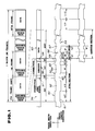
- a recording format of a recording medium in accordance with a first embodiment of the present invention is illustrated therein in the form of a magneto-optical disk wherein information is recorded by offsetting portions of a track 50 thereof along its width to thereby store information.
- the magneto-optical disk of Fig. 1 includes a vertically magnetized film having magneto-optical properties and disposed on a transparent base plate.
- One or more spirally or concentrically extending tracking guide grooves, also known as "pregrooves” are preformed in the magneto-optical disk to define recording tracks either in the pregrooves or in the lands therebetween.
- the tracks are formed with a plurality of portions, such as portions 52 and 54, offset in the direction of the track width in order to provide reproduce-only subsidiary information including at least certain control signals, such as sync signals or clock signals.
- each block or sector of the recording track which functions as the information recording unit includes 98 frames designated sequentially from the 0'th to the 97'th frame.
- Each such frame has a length equivalent to 588 channel clock periods T (that is, 588T) of the principal information recorded along the length of the recording track and includes recording regions for frame sync signals, subcodes and data, including parity data.
- T that is, 588T
- a frame sync signal region 56 having a length equivalent to 24T is provided at the leading edge of each frame, followed sequentially by a connection region 57 having a length equivalent to 3T, a subcode region 58 having a length equivalent to 14T and a further 3T connection region 59.
- the remaining region of the frame is a data region 60 having a length equivalent to 544T which serves to record 32 words or bytes of sample data and parity data modulated according to an eight-to-fourteen modulation (EFM) technique.
- EFM eight-to-fourteen modulation
- Fig. 1 also illustrates a specific example of the recording of subsidiary information signals by offsetting portions of the recording track in the direction of its width.
- the recorded information takes the form of sync signals recorded in a leading section of each frame having a length equivalent to 44T and including two successive 11T transition segments 61 and 62, followed successively by a pair of 7T segments 63 and 64 and a pair of 4T segments 65 and 66.
- additional subsidiary information is recorded in the form of offset portions of the recording track which, in this example, represent address information wherein the offset portions each have a length equivalent to an integral multiple of the channel clock period T of the principal information to be recorded in the recording track.
- the information recorded by offsetting in the direction of the track width is phase encoded (PE) with a bit slot of 8T; alternatively, a biphase mark system in accordance with an eight-to-fourteen modulation (EFM) technique may also be used.
- EFM eight-to-fourteen modulation
- the sync signals recorded in the manner described above are used for frame synchronization, while the first two 8T segments of the 544T data region 67 provide a pair of bits 68 representing synchronizing sector (or block) marks SM for block or sector synchronization, each block or sector consisting of 98 frames in this example.
- the initial two bits of the initial frame's data region are phase encoded with a value "11", while the corresponding offset portions of the remaining frames of the block are phase encoded with a value "10".
- FIG. 2 the date format for information recorded in the offset portions of the recording track corresponding with the 544T data region of each frame is illustrated therein.
- sector mark 68 following the above described sector mark 68 are successively arranged an 8-bit binary coded decimal (BCD) minute address (MA), an 8-bit (BCD) second address (SA), an 8-bit (BCD) block address (BA), and an 8-bit (BCD) frame address (FA) including a total of 34 bits each occupying a length equivalent to 8T and altogether occupying one-half of the 544T data region.
- BCD binary coded decimal
- SA 8-bit
- SBCD block address
- FA 8-bit frame address
- the remaining half of the data region includes a further 34 bits of offset data corresponding with the inverse of the data recorded in the first half of the data region so that the sector mark, minute address, second address, block address and frame address are recorded twice in each frame by offsetting portions of the track along its width.
- the foregoing addresses are recorded in the standard compact disk (CD) format in which the minute address has a range of "00" to "99", the second address has a range of "00" to 59" and the block address has a range of "00" to "74", expressed in binary coded decimal format. Accordingly, the foregoing minute, second and block addresses provide a total of 450,000 separate addresses.
- the frame address has a range of "00" to "97” also expressed in binary coded decimal format.
- the block address is recorded twice in each frame by means of offsetting the track as described above, the block address is readily obtained by reading only a single frame as opposed to prior recording formats which require the reproduction of an entire block of information to access its address. In this advantageous embodiment, therefore, high-speed accessing is enabled by reading the block address at the position of any frame therein. Moreover, since a total of 196 block addresses are recorded in a block totaling 98 frames, it is unlikely that the block address will prove unreadable, thus providing improved reliability. In contrast to the preexisting CD format, the provision of frame addresses in the present embodiment enables accessing on a frame-by-frame basis. Also, the provision of a sector mark at the leading edge of each frame enables the ready identification of the leading edge of each block.
- FIG. 3 a further embodiment of an address format recorded in the form of offset portions of a recording track is illustrated therein.
- the format as illustrated in Fig. 3 includes a 24 bit block address BA including the 24 bits of the minute, second and block addresses, MA, SA and BA of Fig. 2, followed in sequence by a 8-bit frame address.
- the embodiment of Fig. 3 is especially useful for addressing data recorded in a disk having a recording density in excess of that provided by the conventional CD format.
- the 24 bit combined address of Fig. 3 provides the ability to identify 224 or 16,777,216 separate address locations.
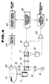
- a magneto-optical disk 10 is provided with a spirally or concentrically extending recording track or tracks having offset portions for recording subsidiary information.
- a spindle motor 11 of the Fig. 4 apparatus is operative to drive a magneto-optical disk 10 rotationally at a constant linear or angular velocity.
- a laser light source 12, such as laser diode, is operative to generate a laser beam for recording and/or reproduction.
- the laser beam is collimated by a collimator lens 13 and the collimated beam therefrom is intercepted by a beam splitter 14 from which the beam emerges to an object lens 15 in the form of a biaxial device which, in turn, serves to focus and track the beam along the surface of the magneto-optical disk 10.
- the beam incident on the polarization light splitter 17 is separated thereby into a P polarization light component which the light splitter 17 projects on the surface of a first photodetector 18, and an S polarization light component which the light splitter 17 projects onto the surface of a second photodetector 19.
- the first and second photodetectors 18 and 19 are adapted for detecting the tracking error signals, focusing error signals and magneto-optical (MO) signals contained in the reflected laser light beam.
- An output of the first photodetector 18 is supplied to a noninverting input of a differential amplifier 20, while an output of the second photodetector 19 is supplied to an inverting input terminal of the differential amplifier 20.
- Differential amplifier 20 produces an output signal proportional to a difference between the output signals from the first and second photodetectors 18 and 19 in order to extract the magneto-optical (MO) signals present in the signals output thereby.
- the magneto optical signals output by the differential amplifier 20 are supplied thereby to an input of a data detection circuit 21.
- the first photodetector 18 is also operative to detect tracking error signals and focusing error signals through the use of appropriate means, such as a 4-segment light receiver.
- the subsidiary information recorded in the track offsets as described above is contained in the high frequency components of the tracking error signals.
- These high frequency components include clock signal components which bear an integral ratio with respect to the clock frequency of the principal information recorded in the recording track and also include sync signals (for example, frame sync signals) which provide synchronization at the predetermined recording unit of the principal information.
- the high frequency components produced by the first photodetector 18 are supplied thereby to an input of a clock/sync signal detection circuit 22 for detecting the clock/sync signals therein.
- a first output of the clock/sync detection circuit 22 is connected with an input of the data detection circuit 21 to supply the clock/sync signals thereto for use in extracting the data contained in the magneto-optical signals which the circuit 21 supplies as reproduced data at an output terminal thereof.
- the Fig. 4 apparatus reproduces the address information stored in the disk 10 in the offset portions of the recording track in order to access the disk for recording the principal information in a recording track thereof. Then, the clock/sync signals produced by the detection circuit 22 from the high frequency components of the offset signals produced by the first photodetector 18 are supplied at a second output of the circuit 22 connected with a first input of a record signal output circuit 23.
- the record signal output circuit 23 receives data to be recorded at a second input thereof which it is operative to demodulate with the use of the clock/sync signals received from the circuit 22.
- the record signal output circuit 23 provides a demodulated data signal at an output terminal thereof connected with an input terminal of a magnetic field modulating drive circuit 24 which is operative to modulate a magnetic field produced by a magnetic head 25 in accordance with the demodulated signal supplied to the driving circuit 24 in order to supply a corresponding magnetic field to the magnetic-optical disk 10.
- a writing laser beam supplied by the laser light source 12 is applied to the disk 10 to effect photomagnetic recording of the signal supplied by the record signal output circuit 23 along the length of a selected recording track of the disk 10.
- the sync signals provided by the offset portions of the recording track may also be used for accessing the disk, as well as for demodulating the data received by the circuit 23.
- the apparatus of Fig. 4 may be readily adapted for use as an optical modulation system, in place of the magnetic field modulation system described hereinabove.
- clock signals for reproducing or recording principal information signals are provided by a source which is completely separate therefrom, which assures accurate frame-by-frame positioning, thus facilitating disk access. Accordingly, it is unnecessary to provide a buffer for absorbing jitter caused by fluctuations in the rotation of the disk, as is required in prior systems wherein clocking or synchronization is achieved only with the use of the principal information signals recorded or to be recorded in the recording track.
- address information in the form of track offsets high accuracy designation and accessing of the frames or blocks at the time of recording and/or reproduction, respectively, is provided. It will be appreciated that recording media, such as optical disks in which sync, address and/or similar information is prerecorded in the form of track offsets, may be mass produced easily by press working during manufacture with the use of a master disk and a stamper.
- a recording format in accordance with a further embodiment of the present invention is provided for recording principal information along the length of a recording track and is similar to the compact disk (CD) format. That is, a single block or sector constituting an information recording unit of the Fig. 5 format includes 98 frames designated successively the 0'th to the 97th frame wherein each frame has a length equivalent to 588 times the channel clock period T or 588T. Each such frame includes respective regions for recording sync signals, subcodes and data, including parity data.
- a 24T sync signal region 70 is provided at the leading edge of each frame, followed successively by a 3T connection bits region 71, a 14T subcode region 72 and a second 3T connection bits region 73.
- Sync signals are recorded magneto-optically in the sync signal region 70 and the following 3T connection bits region 71 in the form of 9 successive 3T transition distances.
- An EFM time code provided in the CD format is recorded as a single word in the 14T subcode region 72.
- FIG. 6 Another recording format in accordance with a further embodiment of the present invention is illustrated in Fig. 6.
- the format as illustrated in Fig. 6 includes a 24T sync signal region 73 at the leading edge of each frame, followed successively by a 3T connection bits region 74, a 14T subcode region 75 and a further 3T connection bits region 76.
- the format as illustrated in Fig. 6 includes a 24T sync signal region 73 at the leading edge of each frame, followed successively by a 3T connection bits region 74, a 14T subcode region 75 and a further 3T connection bits region 76.
- a pattern of 13 successive 3T transition distances is recorded in the 24T sync signal region 73, the successive 3T connection bits region 74 and the 14T subcode region 75, while a pattern of two successive 11T transition distances is recorded similarly in a 24T sync signal region 77 in each of the first through the 97th frames.
- This pattern of two successive 11T transition distances is referred to as an out-of-rule pattern which is not provided in the EFM system and is used for frame synchronization.
- the recording tracks illustrated in Figs. 5 and 6 also include preformed offsets in the direction of the track width which serve to record subsidiary information signals.
- sync signals are recorded in the first 44T transition distances at the leading edge of each frame including two successive 11T transition distance offset portions followed successively by a 7T offset portion, and 11T region and a 4T offset portion.
- the 11T region is constituted either by a single 11T offset portion (in the case of the 0'th frame) or by a pair of 7T and 4T offset portions (in the case of the 1st through 97th frames).
- the sync signals thus provided are used for frame synchronization.
- this pair of 4T transition distances (designated 78 and 76) of the first (or 0'th) frame of the block is distinguishable from the remaining frames as the final two 4T transition distances are phase encoded to represent a "0" value by virtue of the signal rise at the end of the first 4T transition distance, thus providing a sector mark at the leading edge of its respective block. It will be seen with reference to Fig. 6 that the same the two 4T transitions distances 78 and 76 of the remaining frames of the block phase encode a value "1" in order to distinguish those frames from the 0'th frame.
- each frame addition subsidiary data such as address data are recorded by offsetting the track in the direction of its width.
- the length of the offset portions are selected to correspond with an integral multiple of the channel clock period T of the principal information recorded in the recording track.
- clocking information is recorded by track offsetting in accordance with a PE modulation scheme wherein each bit slot is equivalent to 8T.
- the clock period is an integral ratio of the channel clock period
- a biphase mark modulation scheme in accordance with an EFM technique may also be used.
- offset data is recorded utilizing the above mentioned PE scheme, wherein one bit slot is equal to 8T
- a total of 68 bits of data (that is, 544/8) can be recorded in the 544T data region 79.
- FIG. 7 an apparatus for reproducing magneto-optically recorded information from the recording track of a magneto-optical disk in accordance with a method of the present invention is illustrated therein, in which subsidiary information, such as address information, is recorded in the form of track offsets and sync signals are recorded in the recording track as magneto-optical signals.
- subsidiary information such as address information
- sync signals are recorded in the recording track as magneto-optical signals.
- elements corresponding with those of the Fig. 4 apparatus bear the same reference numerals.
- the magneto-optical RF signal (MORF signal) output by the differential amplifier 20 is supplied thereby to the input of a magneto-optical (MO) data detection circuit 31 corresponding with the data detection circuit 21 of Fig. 4.
- the first photodetector 18 supplies the tracking error signals and focusing error signals produced thereby to an RF signal regenerating circuit 32 which is operative to extract RF subsidiary signals recorded as track offsets from the high frequency components of the tracking error signals.
- the RF signal regenerating circuit 32 outputs the high frequency components of the tracking error signal including clock signal components having the same frequency as the clocks of the principal information recorded magneto-optically in the recording track, together with sync signals providing synchronization at the level of the predetermined recording unit of the principal information, such as frame sync signals.
- the high frequency components of the tracking error signal or RF signal output by the regenerating circuit 32 are supplied thereby separtely to a phase locked loop (PLL) 33, a sync detection circuit 34 and an address decoder 35 for detecting the clock and frame sync signals.
- the oscillation frequency of the PLL 33 is thus synchronized with the frequency of the clock components contained in the RF signal.
- the clocks produced by the PLL 33 are provided thereby to the sync detection circuit 34, address decoder 35 and to a timing generator circuit 36.
- the sync detection circuit 34 is operative to detect the sync signals present in the high frequency components output by the RF signal regenerating circuit 32 with the use of the clock synchronized output of the PLL 33.
- the sync signals thus detected by the sync detection circuit 34 are provided thereby to the timing generator 36.
- the address decoder 35 is operative to decode the frame address present in the output from the RF signal regenerating circuit 32 and outputs the decoded frame address to a controller 38.
- the timing generator circuit 36 and the controller 38 together govern the operation of a phase locked loop (PLL) 37 and a changeover switch 39.
- the PLL 37 is operative to supply clocks to the magneto-optical data detection circut 31 for detecting the principal information recorded magneto-optically in the recording track which it supplies as reproduced data to an output terminal 30 of the Fig. 7 apparatus.
- the PLL 37 is synchronized either with the clock signal components recorded magneto-optically in the recording track or with the clock signal components recorded as track offset signals, depending on the state of the switch 39 as controlled by the timing generator circuit 36 and the controller 38.
- a recording track 100 of the magneto-optical disk 10 is illustrated therein in which a plurality of magneto-optical signals indicated by their respective magnetic pluralities N or S are recorded therein.
- the recording track 100 is also provided with a plurality of offset portions, such as portions 102 and 104, recording subsidiary information.
- an RF signal reproduced from the offset portions of the recording track 100 of Fig. 8 is illustrated therein together with a corresponding magneto-optical RF (MORF) signal reproduced from the same recording track 100.
- MORF magneto-optical RF
- the clock components recorded as offset portions of the track are detected in order to synchronize the recording of the magneto-optical signals therein.
- there typically is a time delay between the reading of the offset portions to detect the clock signals and the recording of the magneto-optical signals for example, due to delays introduced by PLL filters or in the circuits which write the magneto-optical signals.
- the magneto-optical signals as recorded are delayed slightly with respect to the corresponding offset portions of the track so that a phase deviation therebetween results. That is, the clock phase of the magneto-optical signal in the recording track differs from that of the offset signal, so that errors may be produced when the principal information is reproduced with the use of clocks detected by reading the offset portions only.
- this potential source of error is eliminated by first utilizing the sync signals or address data recorded in the track offsets for capturing the clock frequency thereof in the output of the PLL 37 at a time when a frame devoid of magneto-optical signals is being reproduced, as illustrated in the left-hand portion of the Fig. 9 waveforms.
- the timing generator circuit 36 and the controller 38 are operative to control the changeover switch 39 to supply the RF signal from the RF signal regenerating circuit 32 as a reference input to the PLL 37 to accomplish frequency stabilization with the use of the offset signals.
- the timing generator circuit 36 is operative to temporarily disable the phase comparator of the PLL 37 as the state of the switch 39 is changed in order to supply the magneto-optical RF signal as a reference to the PLL 37, thus to avoid the adverse effects of chatter occurring when the state of the switch 39 is changed.
- the timing generator circuit 36 re-enables the phase comparator of the PLL 37 which then is operable to capture the phase of the magneto-optical RF signal so that the output of the PLL 37 is matched in phase and frequency to the clocks contained in the magneto-optical RF signal in order to supply a phase and frequency matched clock to the magneto-optical data detection circuit 31 to accurately reproduce the principal information recorded magneto-optically in the recording track.
- Optical data recording techniques which do not make use of track offsetting in accordance with the present invention for recording clock components require the provision of a long preamble region in the recording track wherein clock components are written in order to permit satisfactory extraction thereof.
- regions of the recording track where magneto-optical signals are not written it is not possible to operate a PLL for clock detection.
- track offsets in accordance with the present invention, it is possible to synchronize the output of a PLL with the appropriate clock frequency even where no magneto-optical signal is available. Accordingly, a significantly shorter preamble of magneto-optical sync signals may be provided for phase capturing since the clock frequency has already been captured, so that the PLL may be stabilized in a shorter period of time.
- Recording media on which subsidiary data, such as sync data or address data, are prerecorded by means of track offsets, such as magneto-optical disks, may be readily mass-produced by means of a press working process when the disks are manufactured using a master disk or a stamper.
Claims (16)
- Support d'enregistrement optique (10) pour stocker des données lisibles optiquement, comprenant au moins une piste d'enregistrement préformée (50, 100) de largeur prédéterminée et s'étendant dans une direction d'enregistrement prédéterminée,
ladite piste d'enregistrement (50, 100) possédant une zone enregistrable s'étendant dans ladite direction d'enregistrement de celle-ci, dans laquelle des données contenant des composantes de signal d'horloge sont enregistrées,
ladite piste d'enregistrement (50, 100) étant munie de parties de décalage prédéterminées (52, 54, 102, 104) s'étendant dans la direction de la largeur de celle-ci, représentant des données enregistrées de décalage, et
caractérisé en ce que :
lesdites parties de décalage (52, 54, 102, 104) sont constituées de telle sorte que lesdites données enregistrées de décalage présentent une fréquence, lors du balayage de ladite piste d'enregistrement (50, 100), reliée par un quotient entier aux composantes de signal d'horloge des données. - Support d'enregistrement optique (10) selon la revendication 1, dans lequel ladite piste d'enregistrement (50, 100) possède un signal d'erreur de suivi de piste enregistré avec celle-ci, possédant une fréquence de signal d'erreur de suivi de piste lors du balayage de ladite piste (50, 100) et dans lequel la fréquence des données enregistrées de décalage est d'une façon distinguable plus élevée que la fréquence de signal d'erreur de suivi de piste du signal d'erreur de suivi de piste obtenu lors du balayage de ladite piste.
- Support d'enregistrement optique (10) selon la revendication 2, dans lequel lesdites données enregistrées de décalage incluent des signaux de synchronisation de trame prédéterminés, chacun d'entre eux identifiant une trame respective constituant une unité d'enregistrement d'information desdites données.
- Support d'enregistrement optique (10) selon la revendication 3, dans lequel lesdites données enregistrées de décalage incluent des informations d'adresse prédéterminées afin d'adresser un nombre prédéterminé desdites trames.
- Support d'enregistrement optique (10) selon la revendication 4, dans lequel ladite information d'adresse inclut une information d'adresse de bloc afin d'indiquer un bloc constitué par une pluralité respective desdites trames.
- Support d'enregistrement optique (10) selon la revendication 4, dans lequel lesdites données enregistrées de décalage incluent une information de front avant de bloc prédéterminée afin d'identifier un front avant d'un bloc correspondant de trames enregistrées dans ladite piste d'enregistrement (50, 100).
- Support d'enregistrement optique selon la revendication 6, dans lequel lesdites données enregistrées de décalage incluent une information prédéterminée associée à chaque trame indiquant si ladite trame est la trame avant du bloc correspondant.
- Support d'enregistrement optique selon l'une quelconque des revendications 1 à 7, dans lequel le support d'enregistrement optique est un disque magnéto-optique (10).
- Procédé d'enregistrement de signaux d'information principale le long d'une direction d'enregistrement d'une piste d'enregistrement (50, 100) prévue dans un support d'enregistrement optique (10), comprenant les étapes de :
fourniture d'un support d'enregistrement optique (10) possédant au moins une piste d'enregistrement (50, 100) possédant des zones de décalage prédéterminées (52, 54, 102, 104) s'étendant dans la direction de la largeur de ladite piste d'enregistrement (50, 100), et
enregistrement desdits signaux d'information principale ;
caractérisé en ce que :
lesdites zones de décalage (52, 54, 102, 104) sont constituées de manière à fournir des données enregistrées de décalage incluant une composante de signal d'horloge possédant une fréquence porteuse d'un quotient entier en relation avec une fréquence d'horloge desdits signaux d'information principale ;
lesdits signaux d'information principale sont enregistrés en utilisant des signaux d'horloge obtenus en reproduisant les données enregistrées de décalage. - Procédé selon la revendication 9, dans lequel ladite étape d'enregistrement desdits signaux d'information principale comprend l'enregistrement desdits signaux d'information principale en utilisant une tête d'enregistrement (12, 25) commandée sur la base desdites données enregistrées de décalage afin que ladite tête d'enregistrement (12, 25) soit de ce fait positionnée pour enregistrer l'information principale.
- Procédé selon les revendications 9 et 10, dans lequel l'étape d'enregistrement desdits signaux d'information principale inclut une phase d'enregistrement récupérant des signaux parmi ces derniers dans une zone prédéterminée de la piste d'enregistrement (50, 100) dudit support d'enregistrement (10) le long de la direction d'enregistrement de celle-ci.
- Procédé de reproduction de signaux d'information principale enregistrés le long d'une direction d'enregistrement d'une piste d'enregistrement (50, 100) constituée dans un support d'enregistrement optique (10), ladite piste d'enregistrement (50, 100) possédant des parties prédéterminées (52, 54, 102, 104) décalées par rapport à une largeur de celle-ci représentant des données enregistrées de décalage, comprenant les étapes de :
reproduction desdits signaux de données de décalage ;
production de signaux d'horloge ; et
reproduction desdits signaux d'information principale,
caractérisé en ce que :
les données enregistrées de décalage incluent des composantes de signaux d'horloge possédant une fréquence porteuse d'un quotient entier en relation avec une fréquence d'horloge desdits signaux d'information principale ;
lesdits signaux d'horloge sont produits en utilisant les signaux de données de décalage reproduits ; et
lesdits signaux d'information principale sont reproduits en utilisant lesdits signaux d'horloge. - Procédé selon la revendication 12, dans lequel ladite étape de reproduction desdits signaux d'information principale comprend la reproduction desdits signaux d'information principale en utilisant une tête de reproduction (12, 18, 19) commandée sur la base desdits signaux de données de décalage de manière à ce que ladite tête de reproduction de données (12, 18, 19) soit ainsi positionnée pour reproduire les signaux d'information principale.
- Procédé selon la revendication 12 ou 13, dans lequel la piste d'enregistrement (50, 100) possède des signaux de motif prédéterminé enregistrés le long de la direction d'enregistrement de celle-ci et dans lequel l'étape de production desdits signaux d'horloge comprend la production desdits signaux d'horloge possédant une fréquence déterminée sur la base desdits signaux de données de décalage possédant une phase déterminée par lesdits signaux d'un motif prédéterminé.
- Appareil pour enregistrer des signaux d'information principale le long d'une direction d'enregistrement d'une piste d'enregistrement (50, 100) prévue dans un support d'enregistrement optique (10), le support d'enregistrement (10) possédant au moins une piste d'enregistrement (50, 100) possédant des zones de décalage prédéterminées (52, 54, 102, 104) s'étendant dans la direction de la largeur de ladite piste d'enregistrement (50, 100), lesdites zones de décalage (52, 54, 102, 104) étant constituées afin de fournir des données enregistrées de décalage, l'appareil comprenant :
un moyen (12, 18) pour reproduire les données enregistrées de décalage ;
un moyen (22) pour dériver des signaux d'horloge ; et
un moyen pour enregistrer lesdits signaux d'information principale,
caractérisé en ce que :
lesdites données enregistrées de décalage incluent une composante de signal d'horloge possédant une fréquence porteuse d'un quotient entier en relation avec une fréquence d'horloge desdits signaux d'information principale ;
lesdits signaux d'horloge sont dérivés à partir des données enregistrées de décalage reproduites ; et
les signaux d'information principale sont enregistrés en utilisant les signaux d'horloge ainsi dérivés. - Appareil pour reproduire des signaux d'information principale enregistrés selon une direction d'enregistrement d'une piste d'enregistrement (50, 100) constituée dans un support d'enregistrement optique (10), ladite piste d'enregistrement (50, 100) possédant des parties prédéterminées (52, 54, 102, 104) décalées par rapport à une largeur de celle-ci représentant des données enregistrées de décalage, comprenant :
un moyen (12, 18, 22) pour reproduire lesdits signaux de données de décalage ;
un moyen (36) pour produire des signaux d'horloge ; et
un moyen (18, 19, 20, 31) pour reproduire lesdits signaux d'information principale ;
caractérisé en ce que :
lesdites données enregistrées de décalage incluent des composantes de signal d'horloge possédant une fréquence porteuse d'un quotient entier en relation avec une fréquence d'horloge desdits signaux d'information principale ;
lesdits signaux d'horloge sont produits en utilisant les signaux de données de décalage reproduits ; et
les signaux d'information principale sont reproduits en utilisant lesdits signaux d'horloge.
Applications Claiming Priority (6)
| Application Number | Priority Date | Filing Date | Title |
|---|---|---|---|
| JP219412/89 | 1989-08-25 | ||
| JP1219412A JP2785368B2 (ja) | 1989-08-25 | 1989-08-25 | ディスク状記録媒体、ディスク状記録体の再生方法及び記録方法 |
| JP1219414A JP2785369B2 (ja) | 1989-08-25 | 1989-08-25 | ディスク状記録媒体 |
| JP219414/89 | 1989-08-25 | ||
| JP225313/89 | 1989-08-31 | ||
| JP1225313A JP2745712B2 (ja) | 1989-08-31 | 1989-08-31 | 信号記録方法及び信号再生方法 |
Publications (3)
| Publication Number | Publication Date |
|---|---|
| EP0414518A2 EP0414518A2 (fr) | 1991-02-27 |
| EP0414518A3 EP0414518A3 (en) | 1991-09-18 |
| EP0414518B1 true EP0414518B1 (fr) | 1995-01-18 |
Family
ID=27330272
Family Applications (1)
| Application Number | Title | Priority Date | Filing Date |
|---|---|---|---|
| EP90309197A Expired - Lifetime EP0414518B1 (fr) | 1989-08-25 | 1990-08-22 | Support d'enregistrement optique, méthode associée et appareil pour enregistrer et en reproduire de l'information |
Country Status (6)
| Country | Link |
|---|---|
| US (1) | US5148422A (fr) |
| EP (1) | EP0414518B1 (fr) |
| AU (1) | AU626446B2 (fr) |
| CA (1) | CA2023963C (fr) |
| DE (1) | DE69016133T2 (fr) |
| MY (1) | MY107087A (fr) |
Families Citing this family (28)
| Publication number | Priority date | Publication date | Assignee | Title |
|---|---|---|---|---|
| EP0441967B1 (fr) * | 1989-08-25 | 1996-04-17 | Sony Corporation | Support d'enregistrement optique, methode d'enregistrement de donnees, et methode de reproduction de donnees |
| US5353276A (en) * | 1990-03-12 | 1994-10-04 | Deutsche Thomson-Brandt Gmbh | Process for recording and/or reproducing digital data on a record carrier |
| JP2897379B2 (ja) * | 1990-09-04 | 1999-05-31 | ソニー株式会社 | アドレス情報再生装置 |
| US5600672A (en) | 1991-03-27 | 1997-02-04 | Matsushita Electric Industrial Co., Ltd. | Communication system |
| USRE40241E1 (en) | 1991-03-27 | 2008-04-15 | Matsushita Electric Industrial Co., Ltd. | Communication system |
| USRE42643E1 (en) | 1991-03-27 | 2011-08-23 | Panasonic Corporation | Communication system |
| USRE39890E1 (en) | 1991-03-27 | 2007-10-23 | Matsushita Electric Industrial Co., Ltd. | Communication system |
| JPH0568226A (ja) * | 1991-09-09 | 1993-03-19 | Pioneer Electron Corp | ビデオデイスクの信号記録方法 |
| JP3269097B2 (ja) * | 1991-10-14 | 2002-03-25 | ヤマハ株式会社 | 光ディスクならびにその記録方法およびその記録装置 |
| WO1993016467A1 (fr) * | 1992-02-14 | 1993-08-19 | Sony Corporation | Support d'enregistrement de donnees, appareil d'enregistrement de donnees, appareil de reproduction de donnees et appareil d'enregistrement/reproduction de donnees |
| US5819000A (en) * | 1992-03-26 | 1998-10-06 | Matsushita Electric Industrial Co., Ltd. | Magnetic recording and playback apparatus |
| USRE38513E1 (en) | 1992-03-26 | 2004-05-11 | Matsushita Electric Industrial Co., Ltd. | Communication system |
| US6728467B2 (en) * | 1992-03-26 | 2004-04-27 | Matsushita Electric Industrial Co., Ltd. | Communication system |
| US6724976B2 (en) * | 1992-03-26 | 2004-04-20 | Matsushita Electric Industrial Co., Ltd. | Communication system |
| US7894541B2 (en) * | 1992-03-26 | 2011-02-22 | Panasonic Corporation | Communication system |
| US5802241A (en) | 1992-03-26 | 1998-09-01 | Matsushita Electric Industrial Co., Ltd. | Communication system |
| US7158577B1 (en) | 1992-03-26 | 2007-01-02 | Matsushita Electric Industrial Co., Ltd. | Communication system |
| US5349576A (en) * | 1992-07-27 | 1994-09-20 | Eastman Kodak Company | Apparatus and method for polarization switching of a readout beam in a magneto-optic storage system |
| US5388085A (en) * | 1993-03-03 | 1995-02-07 | International Business Machines Corporation | Apparatus and method for accessing sectors of a rotating disk |
| JPH06338141A (ja) * | 1993-03-29 | 1994-12-06 | Nippon Hoso Kyokai <Nhk> | 追記型記録媒体、フォーマット装置および方法、データ読みだし装置および方法、ならびにデータ書き込み装置および方法 |
| JPH07130092A (ja) * | 1993-11-05 | 1995-05-19 | Sony Corp | ディスク記録装置、ディスク再生装置およびディスク状記録媒体 |
| JPH08203209A (ja) * | 1995-01-26 | 1996-08-09 | Alps Electric Co Ltd | ディスク媒体及びディスク媒体への書き込み方式 |
| US5917910A (en) * | 1995-10-16 | 1999-06-29 | Sony Corporation | Encrypting method and apparatus, recording method, decrypting method and apparatus, and recording medium |
| AU4725797A (en) | 1997-05-28 | 1998-12-30 | Sanyo Electric Co., Ltd. | Recording medium and reproducing apparatus therefor |
| US7701836B2 (en) | 2001-11-27 | 2010-04-20 | Hewlett-Packard Development Company, L.P. | Re-writable optical disk having reference clock information permanently formed on the disk |
| JP2001148123A (ja) * | 1999-11-22 | 2001-05-29 | Sony Corp | 光ディスク、記録及び/又は再生装置及び方法 |
| JP2003203341A (ja) * | 2001-11-02 | 2003-07-18 | Victor Co Of Japan Ltd | 光ディスク、光ディスク記録再生装置及び光ディスク記録再生方法 |
| BRPI0517691A (pt) * | 2004-11-08 | 2008-10-14 | Matsushita Electric Ind Co Ltd | mìdia de gravação de informações óticas, seu método de gravação/reprodução de informações, e dispositivo de gravação/reprodução de informações |
Family Cites Families (14)
| Publication number | Priority date | Publication date | Assignee | Title |
|---|---|---|---|---|
| US3874586A (en) * | 1972-12-18 | 1975-04-01 | Addressograph Multigraph | Information-carrying article and reading apparatus and method |
| US4364118A (en) * | 1979-06-25 | 1982-12-14 | Hitachi, Ltd. | Optical disk and optical information processor |
| US4432870A (en) * | 1981-05-06 | 1984-02-21 | Protectaire Systems Company | Sludge removal apparatus |
| NL8102621A (nl) * | 1981-05-29 | 1982-12-16 | Philips Nv | Inrichting voor het beschrijven en/of uitlezen van een registratiedrager. |
| JPS57208647A (en) * | 1981-06-18 | 1982-12-21 | Toshiba Corp | Optical disk for recording of information |
| FR2523349A1 (fr) * | 1982-03-12 | 1983-09-16 | Thomson Csf | Procede et dispositif optique de generation de signaux d'asservissements de la position d'une tache d'exploration des pistes d'un support d'information |
| FR2523347B1 (fr) * | 1982-03-12 | 1988-11-04 | Thomson Csf | Support d'information mobile pregrave et dispositif optique de suivi de piste mettant en oeuvre un tel support |
| FR2528605B1 (fr) * | 1982-06-15 | 1987-11-20 | Thomson Csf | Procede et dispositif optique de focalisation d'un faisceau d'energie lumineuse sur un plan de reference d'un support d'information ainsi que ce support |
| FR2567673B1 (fr) * | 1984-07-10 | 1986-11-07 | Thomson Alcatel Gigadisc | Support d'information inscriptible optiquement selon une piste definie par des motifs de pregravure et dispositif optique de suivi de piste mettant en oeuvre un tel support |
| FR2581784B1 (fr) * | 1985-05-10 | 1994-03-25 | Thomson Alcatel Gigadisc | Support d'information a pregravure et son dispositif de lecture optique |
| US4879708A (en) * | 1985-07-30 | 1989-11-07 | Laser Magnetic Storage International Company | Optical disk tracking and seeking systems specific track formats using wobbled pits |
| JPS63104225A (ja) * | 1986-10-21 | 1988-05-09 | Csk Corp | 光記録媒体のトラツキング方式 |
| JP2550051B2 (ja) * | 1987-02-25 | 1996-10-30 | 株式会社日立製作所 | 光カード,光カードの記録再生方法,及び,光カード記録再生装置 |
| NL8701632A (nl) * | 1987-07-10 | 1989-02-01 | Philips Nv | Systeem voor het optekenen en/of uitlezen van een informatiesignaal, een registratiedrager, een opteken en/of uitleesinrichting voor toepassing in een dergelijk systeem, en een inrichting en werkwijze voor het vervaardigen van een dergelijke registratiedrager. |
-
1990
- 1990-08-21 US US07/570,432 patent/US5148422A/en not_active Expired - Lifetime
- 1990-08-22 DE DE69016133T patent/DE69016133T2/de not_active Expired - Lifetime
- 1990-08-22 EP EP90309197A patent/EP0414518B1/fr not_active Expired - Lifetime
- 1990-08-24 CA CA002023963A patent/CA2023963C/fr not_active Expired - Lifetime
- 1990-08-24 MY MYPI90001438A patent/MY107087A/en unknown
- 1990-08-24 AU AU61341/90A patent/AU626446B2/en not_active Ceased
Also Published As
| Publication number | Publication date |
|---|---|
| CA2023963C (fr) | 1999-07-20 |
| EP0414518A2 (fr) | 1991-02-27 |
| DE69016133D1 (de) | 1995-03-02 |
| AU6134190A (en) | 1991-02-28 |
| MY107087A (en) | 1995-09-30 |
| US5148422A (en) | 1992-09-15 |
| AU626446B2 (en) | 1992-07-30 |
| CA2023963A1 (fr) | 1991-02-26 |
| DE69016133T2 (de) | 1995-09-07 |
| EP0414518A3 (en) | 1991-09-18 |
Similar Documents
| Publication | Publication Date | Title |
|---|---|---|
| EP0414518B1 (fr) | Support d'enregistrement optique, méthode associée et appareil pour enregistrer et en reproduire de l'information | |
| US5587901A (en) | Optical recording medium having a pre-formed recording track which is offset along its width to record frame sync signals of information | |
| EP0414516B1 (fr) | Support d'enregistrement optique | |
| EP0278006A1 (fr) | Dispositif a disque et support d'enregistrement en forme de disque | |
| JP2807362B2 (ja) | 情報再生装置 | |
| EP0419239B1 (fr) | Milieu et méthode d'enregistrement d'information | |
| JP2785368B2 (ja) | ディスク状記録媒体、ディスク状記録体の再生方法及び記録方法 | |
| JP2785369B2 (ja) | ディスク状記録媒体 | |
| JP2745712B2 (ja) | 信号記録方法及び信号再生方法 | |
| JP2743507B2 (ja) | 記録媒体及び信号再生装置 | |
| JP3191376B2 (ja) | 情報記録方法 | |
| JP2953711B2 (ja) | 光ディスクの記録方法及びその再生方法 | |
| KR100233665B1 (ko) | 광디스크의 정보 기록용 섹터내 동기화 정보 검출 방법 및장치 | |
| JP2745713B2 (ja) | 情報記録方法、情報再生方法及び記録媒体 | |
| JP2822252B2 (ja) | 記録方法、記録媒体及び記録再生装置 | |
| JP2830228B2 (ja) | トラッキング方法 | |
| KR100195555B1 (ko) | 기록 장치 및 재생장치 | |
| JP3223881B2 (ja) | 情報記録装置 | |
| JP2812321B2 (ja) | ディスク状記録媒体 | |
| JP3191763B2 (ja) | 情報記録媒体 | |
| JPH03119520A (ja) | 信号記録方法 | |
| JPS6394436A (ja) | 光デイスクおよび光学的記録装置 | |
| JPH0388125A (ja) | 記録媒体、情報記録方法及び情報再生方法 | |
| JP2003203357A (ja) | 情報記憶媒体、情報記録装置、情報再生装置、情報記録方法、及び情報再生方法 |
Legal Events
| Date | Code | Title | Description |
|---|---|---|---|
| PUAI | Public reference made under article 153(3) epc to a published international application that has entered the european phase |
Free format text: ORIGINAL CODE: 0009012 |
|
| AK | Designated contracting states |
Kind code of ref document: A2 Designated state(s): DE FR GB NL |
|
| PUAL | Search report despatched |
Free format text: ORIGINAL CODE: 0009013 |
|
| RHK1 | Main classification (correction) |
Ipc: G11B 7/013 |
|
| AK | Designated contracting states |
Kind code of ref document: A3 Designated state(s): DE FR GB NL |
|
| 17P | Request for examination filed |
Effective date: 19920226 |
|
| 17Q | First examination report despatched |
Effective date: 19931214 |
|
| GRAA | (expected) grant |
Free format text: ORIGINAL CODE: 0009210 |
|
| AK | Designated contracting states |
Kind code of ref document: B1 Designated state(s): DE FR GB NL |
|
| REF | Corresponds to: |
Ref document number: 69016133 Country of ref document: DE Date of ref document: 19950302 |
|
| ET | Fr: translation filed | ||
| PLBE | No opposition filed within time limit |
Free format text: ORIGINAL CODE: 0009261 |
|
| STAA | Information on the status of an ep patent application or granted ep patent |
Free format text: STATUS: NO OPPOSITION FILED WITHIN TIME LIMIT |
|
| 26N | No opposition filed | ||
| PGFP | Annual fee paid to national office [announced via postgrant information from national office to epo] |
Ref country code: NL Payment date: 19960828 Year of fee payment: 7 |
|
| PG25 | Lapsed in a contracting state [announced via postgrant information from national office to epo] |
Ref country code: NL Free format text: LAPSE BECAUSE OF NON-PAYMENT OF DUE FEES Effective date: 19980301 |
|
| NLV4 | Nl: lapsed or anulled due to non-payment of the annual fee |
Effective date: 19980301 |
|
| REG | Reference to a national code |
Ref country code: GB Ref legal event code: IF02 |
|
| PGFP | Annual fee paid to national office [announced via postgrant information from national office to epo] |
Ref country code: FR Payment date: 20090814 Year of fee payment: 20 |
|
| PGFP | Annual fee paid to national office [announced via postgrant information from national office to epo] |
Ref country code: DE Payment date: 20090821 Year of fee payment: 20 Ref country code: GB Payment date: 20090818 Year of fee payment: 20 |
|
| REG | Reference to a national code |
Ref country code: GB Ref legal event code: PE20 Expiry date: 20100821 |
|
| PG25 | Lapsed in a contracting state [announced via postgrant information from national office to epo] |
Ref country code: GB Free format text: LAPSE BECAUSE OF EXPIRATION OF PROTECTION Effective date: 20100821 |
|
| PG25 | Lapsed in a contracting state [announced via postgrant information from national office to epo] |
Ref country code: DE Free format text: LAPSE BECAUSE OF EXPIRATION OF PROTECTION Effective date: 20100822 |