EP0413845A1 - Méthode pour la détection précoce de dommages aux éléments des machines - Google Patents
Méthode pour la détection précoce de dommages aux éléments des machines Download PDFInfo
- Publication number
- EP0413845A1 EP0413845A1 EP89115599A EP89115599A EP0413845A1 EP 0413845 A1 EP0413845 A1 EP 0413845A1 EP 89115599 A EP89115599 A EP 89115599A EP 89115599 A EP89115599 A EP 89115599A EP 0413845 A1 EP0413845 A1 EP 0413845A1
- Authority
- EP
- European Patent Office
- Prior art keywords
- damage
- frequency
- detected
- determined
- signal components
- Prior art date
- Legal status (The legal status is an assumption and is not a legal conclusion. Google has not performed a legal analysis and makes no representation as to the accuracy of the status listed.)
- Granted
Links
Images
Classifications
-
- G—PHYSICS
- G07—CHECKING-DEVICES
- G07C—TIME OR ATTENDANCE REGISTERS; REGISTERING OR INDICATING THE WORKING OF MACHINES; GENERATING RANDOM NUMBERS; VOTING OR LOTTERY APPARATUS; ARRANGEMENTS, SYSTEMS OR APPARATUS FOR CHECKING NOT PROVIDED FOR ELSEWHERE
- G07C3/00—Registering or indicating the condition or the working of machines or other apparatus, other than vehicles
-
- G—PHYSICS
- G01—MEASURING; TESTING
- G01H—MEASUREMENT OF MECHANICAL VIBRATIONS OR ULTRASONIC, SONIC OR INFRASONIC WAVES
- G01H1/00—Measuring characteristics of vibrations in solids by using direct conduction to the detector
- G01H1/003—Measuring characteristics of vibrations in solids by using direct conduction to the detector of rotating machines
-
- G—PHYSICS
- G01—MEASURING; TESTING
- G01M—TESTING STATIC OR DYNAMIC BALANCE OF MACHINES OR STRUCTURES; TESTING OF STRUCTURES OR APPARATUS, NOT OTHERWISE PROVIDED FOR
- G01M13/00—Testing of machine parts
- G01M13/04—Bearings
- G01M13/045—Acoustic or vibration analysis
Definitions
- the invention relates to a method for early detection of damage to machine parts, in particular to roller bearings, in which forced vibrations are detected with the aid of a vibration sensor.
- a method of the type mentioned, in which forced machine vibrations are detected on the machine with the aid of vibration sensors, is known from DE-PS 32 45 505. This is done with the help a first structure-borne noise parameter in the high-frequency range and a second structure-borne noise parameter in the low-frequency range of the frequency spectrum are measured by vibration sensors and the two measured values are compared with the aid of a comparator. From the measured values of the first structure-borne noise parameter and the second structure-borne noise parameter, the auto power spectrum Gll or G22 and the cross-power spectrum G12 are formed from both structure-borne noise parameters; the coherence function is formed from these values and an increase in the coherence function is used as an early damage detection signal. With this method, early detection of damage can be carried out independently of the upstream determination of reference values, but this method is not suitable for estimating the remaining service life of the machine part.
- the object of the invention is therefore to enable early detection of damage which, in addition to a description of the condition of the machine part, enables an estimation of the remaining service life of the machine part.
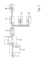
- Figure 1 shows a schematic representation of a device for performing the method according to the invention.
- the device shown schematically is used for the early detection and assessment of bearing damage.
- 1 designates a vibration sensor, with the help of which the forced vibrations of the machine resulting from damaged roller bearings as well as unavoidable disturbances occur when the kinematics are strengthened vibrations are detected.
- the measurement signal is adapted to the device for further processing, for example an amplification or weakening of the measurement signal.
- the signal required for further processing for example the oscillation path, is obtained from the measured signal, for example the measured acceleration.
- the signal is digitized and stored in the memory 5 for further processing.
- the interference signal component is eliminated from the signal which can be further processed.
- the measured time function y (t) which contains useful and interference signals, is compared with a theoretically calculated time function x (t) that only corresponds to the useful signal.
- the rolling bearing and the loading mechanism are mapped mathematically.
- an unevenness function x is defined depending on the location along the path of the rolling elements, which for the individual damage cases such. B. scratches, dimples, cracks or breaks is different. Including the geometry of the rolling elements and the operational bearing force, there is a corresponding deformation between the outer ring and the bearing housing. With the number of rolling elements and the rotational speed of the rotor, there is a time-dependent deformation function x A, i (t) at every location i between the outer ring and the bearing housing. This deformation function also represents mechanical shafts in the bearing housing.
- the transmission paths from all locations i to one Measuring location, for example on the outside of the bearing housing can preferably be represented in a known manner as a transfer function by means of continuum mechanics.
- the time function y (t), z. B. as an acceleration time function.
- the signal components y L (t) generated by the bearing are determined by correlating y (t) with the deformation function x A, i (t).
- the signal and interference signal can be separated using a method as described, for example, in the magazine Konstrutation 31 (1979) No. 9, pages 345 to 351 "separation of stress-time functions according to their origin ".
- the interference components can be eliminated by correlating the measurement signals of both channels and distinguishing the correlated components from the non-correlated components.
- the useful signal is assigned to one or the other part.
- the frequency spectrum preferably as a spectral power density, is determined for each component y d , y s , y n of the time function y L (t) recorded at the measuring location and adjusted for the interference components.
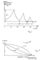
- the frequency ranges are expediently determined by specifying an absolute or relative dynamic range, as illustrated in FIG. 2.
- the spectral power density is plotted in FIG. 2 as a function of the frequency; the defined frequency ranges A, B and C are also entered.
- the frequency components that mainly contribute to the intensity are determined. In this case, distortions of the measurement signal in the frequency spectrum caused by the transmission path or the measurement technology can be corrected, for example by raising or lowering higher frequencies.
- the damage-determining intensities for the specific frequency ranges are now determined by means of frequency analyzes, the size, scope and shape of the frequency distribution being determined.
- the combination of frequency range and frequency distribution results in a stress factor for the rolling bearing.
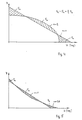
- the frequency distribution of class crossings is determined for each of these areas. These frequency distributions are still typed separately for each component y d , y s , y n , as illustrated in FIG. 3.
- the PI factor (pattern intensity) is then used for each signal component i and each frequency range k formed where ⁇ Maximum value of the frequency distribution of the respective signal component y in the respective frequency range RMS RMS value of the respective signal component y in the respective frequency range H o zero crossing number of the frequency distribution
- the stress spectrum is first derived from the data determined so far. This can unite happening from the PI factors determined or more precisely by combining the frequencies determined there.
- Each PI factor multiplied by ⁇ 2 and provided with the associated mean frequency, represents a single-stage amplitude spectrum for which the damage component is calculated.
- the sum of the damage proportions for each PI factor gives the total damage sought up to the point in time considered.
- the history is not necessary as long as the PI factors are below a limit. After that, the history is included in the degree of damage determined at the time of observation. The remaining life is an immediate measure of the remaining operating time, for which reason assumptions about the damage progress over time have to be made. These assumptions can be based on generally valid empirical values obtained once. A trend analysis as in known methods is therefore generally not necessary.
- the advantage of the method according to the invention resides in the fact that the aforementioned calculation is carried out on the stress side and thus directly damage-related, not on the signal side as in methods with trend analysis. If necessary, the meaningfulness of the calculated values can be increased by continuously recording the PI factors in a trend analysis, but on the stress side.
- the determined signal components y d , y s and y n can also be used to draw conclusions about certain types of bearing damage. Local damage is characterized by the presence of all three signal components, while extensive damage such as pitting, dimples, Rie fen or roughness predominantly the signal components y s and y n are present.
- the calibration can be done either by calculation or by measurement.
- the arithmetic basic stress for the respective bearing is known from the manufacturer's information.
- a multiple of the basic level y can be converted into a multiple of the basic load of the bearing.
- the implementation is dependent on the overall transmission behavior, ie the mathematical mapping as explained above, in the simplest case linear.
- an output device 8 is provided for the display of measured values or for the display of characteristic values, which output device 8 can be designed, for example, as a display, screen device or printer.
Priority Applications (2)
| Application Number | Priority Date | Filing Date | Title |
|---|---|---|---|
| EP89115599A EP0413845B1 (fr) | 1989-08-24 | 1989-08-24 | Méthode pour la détection précoce de dommages aux éléments des machines |
| DE8989115599T DE58904226D1 (de) | 1989-08-24 | 1989-08-24 | Verfahren zur schadensfrueherkennung an maschinenteilen. |
Applications Claiming Priority (1)
| Application Number | Priority Date | Filing Date | Title |
|---|---|---|---|
| EP89115599A EP0413845B1 (fr) | 1989-08-24 | 1989-08-24 | Méthode pour la détection précoce de dommages aux éléments des machines |
Publications (2)
| Publication Number | Publication Date |
|---|---|
| EP0413845A1 true EP0413845A1 (fr) | 1991-02-27 |
| EP0413845B1 EP0413845B1 (fr) | 1993-04-28 |
Family
ID=8201798
Family Applications (1)
| Application Number | Title | Priority Date | Filing Date |
|---|---|---|---|
| EP89115599A Expired - Lifetime EP0413845B1 (fr) | 1989-08-24 | 1989-08-24 | Méthode pour la détection précoce de dommages aux éléments des machines |
Country Status (2)
| Country | Link |
|---|---|
| EP (1) | EP0413845B1 (fr) |
| DE (1) | DE58904226D1 (fr) |
Cited By (9)
| Publication number | Priority date | Publication date | Assignee | Title |
|---|---|---|---|---|
| WO1994028388A1 (fr) * | 1993-05-25 | 1994-12-08 | Commonwealth Scientific And Industrial Research Organisation | Procede et systeme de detection d'une discontinuite dans une structure |
| DE19600640A1 (de) * | 1996-01-10 | 1997-07-17 | Wilo Gmbh | Sensor für eine Motorkreiselpumpe |
| EP0939308A2 (fr) * | 1998-02-18 | 1999-09-01 | Prüftechnik Dieter Busch Ag | Dispositif pour la réconnaissance ou l'analyse des dommages aux machines |
| EP1077372A2 (fr) * | 1999-08-16 | 2001-02-21 | Prüftechnik Dieter Busch Ag | Procédé et dispositif de détermination d'endommagements de pièces de machine à mouvement cyclique |
| US6591682B1 (en) | 2000-08-14 | 2003-07-15 | Pruftechnik Dieter Busch Ag | Device and process for signal analysis |
| WO2009143939A3 (fr) * | 2008-04-18 | 2010-02-04 | CFS Bühl GmbH | Procédé, dispositif et couteau pour découper des produits alimentaires |
| DE102009033614A1 (de) * | 2009-07-17 | 2011-01-20 | Klippel, Wolfgang, Dr. | Anordnung und Verfahren zur Erkennung, Ortung und Klassifikation von Defekten |
| RU2644646C1 (ru) * | 2017-05-18 | 2018-02-13 | Анвар Рашитович Валеев | Способ диагностики технического состояния роторного оборудования |
| DE102019211693A1 (de) * | 2019-08-05 | 2021-02-11 | Robert Bosch Gmbh | Verfahren und Vorrichtung zur Ermittlung einer Langzeitschädigung einer Komponente durch Vibrationsbeaufschlagung |
Families Citing this family (2)
| Publication number | Priority date | Publication date | Assignee | Title |
|---|---|---|---|---|
| DE10144076A1 (de) * | 2001-09-07 | 2003-03-27 | Daimler Chrysler Ag | Vorrichtung und Verfahren zur Früherkennung und Vorhersage von Aggregateschädigungen |
| DE102006059945B4 (de) * | 2006-12-19 | 2013-03-21 | Volkswagen Ag | Verfahren zur Bestimmung der Stoßbelastung beim Anschlagen eines bewegbaren Elements an einen Endanschlag und Vorrichtung hierfür |
Citations (4)
| Publication number | Priority date | Publication date | Assignee | Title |
|---|---|---|---|---|
| US4164149A (en) * | 1978-05-09 | 1979-08-14 | Shigeo Okubo | Method and system for monitoring the angular deformation of structural elements |
| DE3245505A1 (de) * | 1982-12-09 | 1984-06-14 | Rheinisch-Westfälischer Technischer Überwachungsverein e.V ., 4300 Essen | Verfahren zur schadensfrueherkennung |
| US4513622A (en) * | 1983-08-22 | 1985-04-30 | Kazansky Aviatsionny Institut Imeni A. N. Tupoleva | Method of forming random vibration spectrum and device therefor |
| DE3703429A1 (de) * | 1987-02-05 | 1988-08-18 | Diskus Werke Frankfurt Main Ag | Messautomatikrechner zur maschinensteuerung und statistischer prozessregelung fuer schleifmaschinen, insbesondere zum schleifen von werkstuecken in kontinuierlicher bearbeitungsfolge |
-
1989
- 1989-08-24 DE DE8989115599T patent/DE58904226D1/de not_active Expired - Fee Related
- 1989-08-24 EP EP89115599A patent/EP0413845B1/fr not_active Expired - Lifetime
Patent Citations (4)
| Publication number | Priority date | Publication date | Assignee | Title |
|---|---|---|---|---|
| US4164149A (en) * | 1978-05-09 | 1979-08-14 | Shigeo Okubo | Method and system for monitoring the angular deformation of structural elements |
| DE3245505A1 (de) * | 1982-12-09 | 1984-06-14 | Rheinisch-Westfälischer Technischer Überwachungsverein e.V ., 4300 Essen | Verfahren zur schadensfrueherkennung |
| US4513622A (en) * | 1983-08-22 | 1985-04-30 | Kazansky Aviatsionny Institut Imeni A. N. Tupoleva | Method of forming random vibration spectrum and device therefor |
| DE3703429A1 (de) * | 1987-02-05 | 1988-08-18 | Diskus Werke Frankfurt Main Ag | Messautomatikrechner zur maschinensteuerung und statistischer prozessregelung fuer schleifmaschinen, insbesondere zum schleifen von werkstuecken in kontinuierlicher bearbeitungsfolge |
Non-Patent Citations (3)
| Title |
|---|
| AUTOMOBILTECHNISCHE ZEITSCHRIFT * |
| KONSTRUKTION * |
| SIEMENS-ZEITSCHRIFT * |
Cited By (15)
| Publication number | Priority date | Publication date | Assignee | Title |
|---|---|---|---|---|
| WO1994028388A1 (fr) * | 1993-05-25 | 1994-12-08 | Commonwealth Scientific And Industrial Research Organisation | Procede et systeme de detection d'une discontinuite dans une structure |
| DE19600640A1 (de) * | 1996-01-10 | 1997-07-17 | Wilo Gmbh | Sensor für eine Motorkreiselpumpe |
| EP0939308A2 (fr) * | 1998-02-18 | 1999-09-01 | Prüftechnik Dieter Busch Ag | Dispositif pour la réconnaissance ou l'analyse des dommages aux machines |
| EP0939308A3 (fr) * | 1998-02-18 | 2002-02-27 | Prüftechnik Dieter Busch Ag | Dispositif pour la réconnaissance ou l'analyse des dommages aux machines |
| EP1746404A1 (fr) * | 1999-08-16 | 2007-01-24 | Prüftechnik Dieter Busch Ag | Procédé et dispositif de détermination d'endommagements de pièces de machine à mouvement cyclique |
| EP1077372A2 (fr) * | 1999-08-16 | 2001-02-21 | Prüftechnik Dieter Busch Ag | Procédé et dispositif de détermination d'endommagements de pièces de machine à mouvement cyclique |
| EP1077372A3 (fr) * | 1999-08-16 | 2002-11-06 | Prüftechnik Dieter Busch Ag | Procédé et dispositif de détermination d'endommagements de pièces de machine à mouvement cyclique |
| US6591682B1 (en) | 2000-08-14 | 2003-07-15 | Pruftechnik Dieter Busch Ag | Device and process for signal analysis |
| WO2009143939A3 (fr) * | 2008-04-18 | 2010-02-04 | CFS Bühl GmbH | Procédé, dispositif et couteau pour découper des produits alimentaires |
| US9272428B2 (en) | 2008-04-18 | 2016-03-01 | Gea Food Solutions Germany Gmbh | Method, device and measuring device for cutting open foodstuff |
| DE102009033614A1 (de) * | 2009-07-17 | 2011-01-20 | Klippel, Wolfgang, Dr. | Anordnung und Verfahren zur Erkennung, Ortung und Klassifikation von Defekten |
| US8401823B2 (en) | 2009-07-17 | 2013-03-19 | Wolfgang Klippel | Method and arrangement for detecting, localizing and classifying defects of a device under test |
| DE102009033614B4 (de) * | 2009-07-17 | 2020-01-23 | Wolfgang Klippel | Anordnung und Verfahren zur Erkennung, Ortung und Klassifikation von Defekten |
| RU2644646C1 (ru) * | 2017-05-18 | 2018-02-13 | Анвар Рашитович Валеев | Способ диагностики технического состояния роторного оборудования |
| DE102019211693A1 (de) * | 2019-08-05 | 2021-02-11 | Robert Bosch Gmbh | Verfahren und Vorrichtung zur Ermittlung einer Langzeitschädigung einer Komponente durch Vibrationsbeaufschlagung |
Also Published As
| Publication number | Publication date |
|---|---|
| EP0413845B1 (fr) | 1993-04-28 |
| DE58904226D1 (de) | 1993-06-03 |
Similar Documents
| Publication | Publication Date | Title |
|---|---|---|
| DE10119209B4 (de) | Fehlerdiagnoseverfahren und -vorrichtung | |
| DE69937737T2 (de) | Beurteilung des zustands eines lagers | |
| DE69825426T2 (de) | System zur prädiktiven diagnose von beweglichen maschinenteilen | |
| DE69732569T2 (de) | System zur erkennung von störungen von elektromotoren | |
| DE102019127085B4 (de) | Lager- und fehlerfrequenzidentifikation anhand von vibrationsspektraldiagrammen | |
| DE60221149T2 (de) | System und verfahren zur identifikation des vorhandenseins von defekten in einer vibrierenden maschine | |
| DE69837847T2 (de) | Vorrichtung zur prüfung der hauptmotorenlager in schienenfahrzeugen | |
| DE3031812C2 (de) | Verfahren zur Vibrationsdiagnose an rotierenden Maschinen | |
| EP1197417B1 (fr) | Méthode et appareil pour détecter des défauts sur les roues d' un véhicule ferroviaire | |
| DE19917541B4 (de) | Verfahren zur Fehlerdiagnose | |
| DE102017124135A1 (de) | Maschinenfehlervorhersage basierend auf einer Analyse von periodischen Informationen in einem Signal | |
| DE102016102328A1 (de) | System zur Diagnose von Anomalien, Diagnoseverfahren und -vorrichtung | |
| EP0413845B1 (fr) | Méthode pour la détection précoce de dommages aux éléments des machines | |
| DE112017007532B4 (de) | Alterungsdegradationsdiagnosevorrichtung und alterungsdegradationsdiagnoseverfahren | |
| EP2623949A1 (fr) | Dispositif de surveillance d'état et procédé de surveillance d'état de composants mécaniques rotatifs | |
| DE112018003079T5 (de) | Drehmaschinensystem-Diagnosevorrichtung, Leistungsumsetzvorrichtung, Drehmaschinensystem und Drehmaschinensystem-Diagnoseverfahren | |
| DE60117049T2 (de) | Maschinenzustandsüberwachungsvorrichtung mit steuerungseinrichtung | |
| EP3081914B1 (fr) | Surveillance d'une machine dotée d'un composant rotatif | |
| DE19702234A1 (de) | Verfahren zur Überwachung und Qualitätsbeurteilung von sich bewegenden und/oder rotierenden Maschinenteilen insbesondere von Maschinenlagern | |
| AT410923B (de) | Verfahren und vorrichtung zur erkennung eines schadhaften wälzlagers von rädern eines schienenfahrzeuges | |
| DE3245505C2 (de) | Verfahren zur Schadensfrüherkennung | |
| DE4217007A1 (de) | Verfahren und Vorrichtung zur Überwachung und Sicherung der Produktqualität | |
| DE112006002009T5 (de) | Bewertungsverfahren für ein Rollenlagerteil | |
| DE102011083858A1 (de) | Verfahren und Anordnung zur Überwachung von Zahnrädern im Betrieb | |
| DE4006948A1 (de) | Verfahren und anordnung zum ueberwachen des verschleisses oder der ermuedung eines zyklisch belasteten bauteils |
Legal Events
| Date | Code | Title | Description |
|---|---|---|---|
| PUAI | Public reference made under article 153(3) epc to a published international application that has entered the european phase |
Free format text: ORIGINAL CODE: 0009012 |
|
| AK | Designated contracting states |
Kind code of ref document: A1 Designated state(s): AT BE CH DE ES FR GB GR IT LI LU NL SE |
|
| RBV | Designated contracting states (corrected) |
Designated state(s): DE FR GB IT |
|
| 17P | Request for examination filed |
Effective date: 19910628 |
|
| 17Q | First examination report despatched |
Effective date: 19920819 |
|
| ITF | It: translation for a ep patent filed |
Owner name: ING. ZINI MARANESI & C. |
|
| GRAA | (expected) grant |
Free format text: ORIGINAL CODE: 0009210 |
|
| AK | Designated contracting states |
Kind code of ref document: B1 Designated state(s): DE FR GB IT |
|
| REF | Corresponds to: |
Ref document number: 58904226 Country of ref document: DE Date of ref document: 19930603 |
|
| ET | Fr: translation filed | ||
| GBT | Gb: translation of ep patent filed (gb section 77(6)(a)/1977) |
Effective date: 19930802 |
|
| PLBI | Opposition filed |
Free format text: ORIGINAL CODE: 0009260 |
|
| 26 | Opposition filed |
Opponent name: SIEMENS AG Effective date: 19940127 |
|
| PGFP | Annual fee paid to national office [announced via postgrant information from national office to epo] |
Ref country code: FR Payment date: 19940711 Year of fee payment: 6 |
|
| PGFP | Annual fee paid to national office [announced via postgrant information from national office to epo] |
Ref country code: GB Payment date: 19940715 Year of fee payment: 6 |
|
| PGFP | Annual fee paid to national office [announced via postgrant information from national office to epo] |
Ref country code: DE Payment date: 19940805 Year of fee payment: 6 |
|
| PLBN | Opposition rejected |
Free format text: ORIGINAL CODE: 0009273 |
|
| STAA | Information on the status of an ep patent application or granted ep patent |
Free format text: STATUS: OPPOSITION REJECTED |
|
| 27O | Opposition rejected |
Effective date: 19950320 |
|
| PG25 | Lapsed in a contracting state [announced via postgrant information from national office to epo] |
Ref country code: GB Effective date: 19950824 |
|
| GBPC | Gb: european patent ceased through non-payment of renewal fee |
Effective date: 19950824 |
|
| PG25 | Lapsed in a contracting state [announced via postgrant information from national office to epo] |
Ref country code: FR Effective date: 19960430 |
|
| PG25 | Lapsed in a contracting state [announced via postgrant information from national office to epo] |
Ref country code: DE Effective date: 19960501 |
|
| REG | Reference to a national code |
Ref country code: FR Ref legal event code: ST |
|
| PG25 | Lapsed in a contracting state [announced via postgrant information from national office to epo] |
Ref country code: IT Free format text: LAPSE BECAUSE OF NON-PAYMENT OF DUE FEES;WARNING: LAPSES OF ITALIAN PATENTS WITH EFFECTIVE DATE BEFORE 2007 MAY HAVE OCCURRED AT ANY TIME BEFORE 2007. THE CORRECT EFFECTIVE DATE MAY BE DIFFERENT FROM THE ONE RECORDED. Effective date: 20050824 |
|
| PLAB | Opposition data, opponent's data or that of the opponent's representative modified |
Free format text: ORIGINAL CODE: 0009299OPPO |