EP0412202A1 - Source d'ondes de choc pour la production d'ondes de choc focalisées avec un réflecteur en forme de paraboloide de révolution - Google Patents
Source d'ondes de choc pour la production d'ondes de choc focalisées avec un réflecteur en forme de paraboloide de révolution Download PDFInfo
- Publication number
- EP0412202A1 EP0412202A1 EP89114925A EP89114925A EP0412202A1 EP 0412202 A1 EP0412202 A1 EP 0412202A1 EP 89114925 A EP89114925 A EP 89114925A EP 89114925 A EP89114925 A EP 89114925A EP 0412202 A1 EP0412202 A1 EP 0412202A1
- Authority
- EP
- European Patent Office
- Prior art keywords
- membrane
- coil
- shock wave
- wave source
- reflector
- Prior art date
- Legal status (The legal status is an assumption and is not a legal conclusion. Google has not performed a legal analysis and makes no representation as to the accuracy of the status listed.)
- Ceased
Links
Images

Classifications
-
- A—HUMAN NECESSITIES
- A61—MEDICAL OR VETERINARY SCIENCE; HYGIENE
- A61B—DIAGNOSIS; SURGERY; IDENTIFICATION
- A61B17/00—Surgical instruments, devices or methods, e.g. tourniquets
- A61B17/22—Implements for squeezing-off ulcers or the like on the inside of inner organs of the body; Implements for scraping-out cavities of body organs, e.g. bones; Calculus removers; Calculus smashing apparatus; Apparatus for removing obstructions in blood vessels, not otherwise provided for
- A61B17/225—Implements for squeezing-off ulcers or the like on the inside of inner organs of the body; Implements for scraping-out cavities of body organs, e.g. bones; Calculus removers; Calculus smashing apparatus; Apparatus for removing obstructions in blood vessels, not otherwise provided for for extracorporeal shock wave lithotripsy [ESWL], e.g. by using ultrasonic waves
- A61B17/2256—Implements for squeezing-off ulcers or the like on the inside of inner organs of the body; Implements for scraping-out cavities of body organs, e.g. bones; Calculus removers; Calculus smashing apparatus; Apparatus for removing obstructions in blood vessels, not otherwise provided for for extracorporeal shock wave lithotripsy [ESWL], e.g. by using ultrasonic waves with means for locating or checking the concrement, e.g. X-ray apparatus, imaging means
- A61B17/2258—Implements for squeezing-off ulcers or the like on the inside of inner organs of the body; Implements for scraping-out cavities of body organs, e.g. bones; Calculus removers; Calculus smashing apparatus; Apparatus for removing obstructions in blood vessels, not otherwise provided for for extracorporeal shock wave lithotripsy [ESWL], e.g. by using ultrasonic waves with means for locating or checking the concrement, e.g. X-ray apparatus, imaging means integrated in a central portion of the shock wave apparatus
-
- G—PHYSICS
- G10—MUSICAL INSTRUMENTS; ACOUSTICS
- G10K—SOUND-PRODUCING DEVICES; METHODS OR DEVICES FOR PROTECTING AGAINST, OR FOR DAMPING, NOISE OR OTHER ACOUSTIC WAVES IN GENERAL; ACOUSTICS NOT OTHERWISE PROVIDED FOR
- G10K9/00—Devices in which sound is produced by vibrating a diaphragm or analogous element, e.g. fog horns, vehicle hooters or buzzers
- G10K9/12—Devices in which sound is produced by vibrating a diaphragm or analogous element, e.g. fog horns, vehicle hooters or buzzers electrically operated
Definitions
- the invention relates to a shock wave source for generating focused shock waves, comprising an essentially hollow cylindrical membrane made of an electrically conductive material, an electrical coil arrangement arranged inside the membrane, which can be acted upon by a high-voltage pulse for the pulse-like drive of the membrane, a concave reflector surrounding the membrane, whose shape is at least approximately that of a paraboloid of revolution and whose central axis essentially corresponds to the central axis of the membrane, and an acoustic propagation medium which fills at least the space between the membrane and the reflector.
- Such electromagnetic shock wave sources can be used for a wide variety of purposes, for example in medicine, in order to non-invasively break up concrements located in the body of a patient or to treat non-invasive pathological tissue changes as well.
- shock wave sources can be used in material testing in order to apply focused shock waves to material samples.
- the shock wave source is suitably acoustically coupled to the object to be irradiated so that the generated shock waves can be introduced into the object.
- the function of such shock wave sources is essentially based on the fact that the diaphragm expands radially when a high voltage pulse is applied to the coil arrangement, as a result of which a pressure pulse in the form of a cylindrical wave is introduced into the propagation medium, which pulse gradually divides into a shock wave.
- the pressure pulse or the shock wave is reflected on the reflector in such a way that the acoustic energy is concentrated in the focal point of the paraboloid of revolution.
- the shock wave source and that too sounding object must be aligned relative to each other so that the area of the object to be sounded is in the focal point of the paraboloid of revolution, which corresponds to the center of the focus area of the shock waves.
- LMS Large Aperture Ringshaped Soundsource
- acoustic lenses DE-OS 33 28 039
- a spherically shaped membrane is provided, from which shock waves originate, which none require further focusing
- the shock wave source of the type mentioned initially cylinder waves are generated, which are then concentrated by reflection on the paraboloid-shaped reflector in a focus.
- the coil arrangement has a plurality of flat coils which are arranged side by side in a cylindrical curved surface within the hollow cylindrical membrane.
- the production of this coil arrangement is associated with a very considerable effort and therefore entails high costs.
- the space available for the coil arrangement is used only incompletely, which is noticeable in that the efficiency of the known shock wave source is significantly below the theoretically possible efficiency.
- the invention has for its object to provide a shock wave source of the type mentioned in such a way that it can be produced with little manufacturing effort and low costs, that a uniform drive of the membrane is ensured and that a high degree of efficiency is achieved.
- this object is achieved in that the coil arrangement has at least one cylinder-wound coil and that the membrane is designed as a thin-walled, smooth tube.
- the manufacturing outlay for the coil arrangement is very small.
- this design of the coil enables optimal use of the space available for the coil arrangement, so that a high degree of efficiency is achieved.
- this design of the coil ensures a uniform drive of the membrane, so that it is subjected to a uniform mechanical stress by the driving forces.
- the membrane is designed as a thin-walled, smooth tube, it is ensured that ideal cylinder waves actually emanate from the membrane, which is essential for a good focusing effect. Finally, due to its design as a thin-walled, smooth tube, the membrane can be produced with minimal effort.
- the advantages of the invention come to the fore if the coil is arranged concentrically to the membrane in accordance with a preferred variant of the invention, since then particularly uniform drive and stress conditions for the membrane are present.
- the membrane is designed as a seamless tube. This measure ensures a long service life of the membrane, since a seam, which must necessarily represent a mechanical weak point, is avoided.
- the membrane preferably has a constant thickness.
- the membrane preferably contains at least one material from the group consisting of aluminum, copper, silver or highly conductive alloys thereof, e.g. Bronzes. Aluminum is preferred as the material for the membrane, since this material has the advantage of high electrical conductivity with good mechanical strength and machinability.
- the turns of the coil must have suitable insulation in order to ensure a sufficient electrical dielectric strength of the coil.
- insulating means are provided between the coil and the inner wall of the membrane. This can be an insulation surrounding the wire of the coil, provided that it has a sufficient insulating effect.
- the insulating means are preferably formed by an insulating film arranged between the inner wall of the membrane and the coil.
- the space located between the inner wall of the membrane and the coil or the insulating means can be subjected to negative pressure. This initially ensures that the membrane is as close as possible to the coil before the generation of a shock wave, which has a positive effect on the efficiency of the shock wave source. This measure also ensures that the membrane is returned to a defined starting position after the generation of a shock wave, so that successively generated shock waves have the same characteristics.
- a further preferred embodiment provides that an ultrasound locating device is arranged in the interior of the coil, by means of which the focus area of the shock waves can be scanned.
- This embodiment is particularly important when the shock wave source is used for medical purposes, e.g. for crushing concrements in a patient's body, the shock wave source then being aligned with the aid of the ultrasound locating device relative to the patient's body such that the target area, e.g. the concrement to be smashed, located in the focus area of the shock waves.
- a particular advantage of this embodiment is that the space already present inside the coil is used to accommodate the ultrasound locating device. No special design measures are therefore required in order to be able to integrate the ultrasound locating device into the shock wave source.
- a further variant of the invention provides that the coil is wound on an electrically insulating material, at least in the region of the coil, of a coil carrier.
- a mechanically stable mounting of the coil is achieved in a simple manner by this measure.
- the coil carrier can have a central bore in which the ultrasound locating device is arranged.
- the shock wave source emits shock waves in the form of pressure pulses and is therefore preferred for treating a patient with focused Shock waves used, in particular for the treatment of stone diseases, bone diseases, but also for the treatment of pathological tissue changes.
- the reflector is formed at least in the region of its reflector surface from a material, preferably from a foam with closed pores, which is acoustically softer than the spread medium, such as water, shock waves are generated in the form of vacuum pulses.
- the shock wave source can then be used in particular for the treatment of pathological tissue changes, for example tumor disorders, since negative pressure promotes the formation of cavitation, which has resulted in damage to cells and tissue in animal experiments.
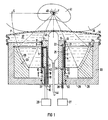
- the shock wave source shown in Fig. 1 has an essentially hollow cylindrical membrane 1 made of an electrically conductive material, which is designed as a thin-walled, smooth, seamless tube of constant thickness.
- the membrane 1 contains at least one material from the group aluminum, copper, silver or their alloys.
- Inside the membrane 1 there is a coil 2, which is wound in the shape of a cylindrical screw on a cylindrical coil carrier 3 made of an electrically insulating material.
- the coil 2 is wound from a wire provided with enamel insulation, preferably enameled copper wire.
- the turns of the coil are fixed in a manner not shown on the coil carrier 3 by means of a suitable immersion or casting resin.
- the coil 2 In order to avoid voltage flashovers between the coil 2 and the membrane 1, the coil 2 is acted upon by high-voltage pulses of high current strength in order to generate shock waves, the coil 2 completely surrounded on its outer lateral surface by an insulating film 4, the thickness of which is exaggerated in FIG. 1 as well as the thickness of the membrane 1 and the coil 2.
- the coil carrier 3 has on its outer lateral surface an annular recess 5 in which the coil 2 and the insulating film 4 are received.
- the length of the recess 5 is equal to the length of the coil 2.
- the depth of the recess 5 is equal to the sum of the thicknesses of the coil 2 and the insulating film 4 or slightly larger than this sum.
- the coil carrier 3 thus has a cylindrical projection 6, 7 on both sides of the coil 2, the diameter of the projections 6, 7 being substantially equal to the inside diameter of the membrane 1. This is placed on the coil carrier 3 with the interposition of sealing rings 10, 11 received in corresponding grooves 8, 9 provided in the lugs 6, 7. With the help of snap rings 12, 13, which abut the ends of the membrane 1 and are received in corresponding grooves 14, 15 of the lugs 6, 7 of the coil carrier 3, the membrane 1 is axially immovably fixed on the coil carrier 3.
- the connections 16, 17 of the coil are guided through angled bores 18, 19 provided in the coil carrier 3 to the end face of the extension 7 of the coil carrier 3 and are connected to a schematically indicated high-voltage pulse generator 20.
- a further groove 21, 22 is provided between the recess 5 of the coil carrier 3 and the grooves 8, 9 receiving the sealing rings 10, 11.
- the grooves 21, 22 are connected via bores 23, 24, which run approximately radially in the bobbin 3, to a bore 25 which extends approximately axially in the bobbin 3, which ends in the region of the end face of the shoulder 7 of the bobbin 3 and by means of a line 26 a vacuum pump 27 schematically indicated in FIG. 1 is connected. It is thus possible to apply a vacuum to the space located between the inner wall of the membrane 1 and the insulating film 4.
- the shock wave source according to FIG. 1 has a pot-shaped housing 28 with a bottom 29 and a cylindrical tubular wall 30.
- the coil support 3 is fixed with its shoulder 7 in a bore 31 of the bottom 29 of the housing 28 with the interposition of a sealing ring 32 such that the common central axis of the membrane 1 and the coil 2 coincides with the central axis of the housing 28.
- An annular reflector 33 is accommodated in the housing 28, the outer lateral surface of which rests on the inside of the wall 30 of the housing 28.
- the reflector 33 rests with its one end face against the bottom 29 of the housing 28 and is fixed axially immovably in the housing 28 by means of a snap ring 35 accommodated in a corresponding groove 34 provided in the wall 30 of the housing 28.
- the housing 28 is closed by means of a flexible bellows 36.
- the entire space enclosed by the bellows 36, the housing 28, the reflector 33, the coil support 3 and the membrane 1 is covered with an acoustic propagation medium 37, e.g. Water, filled.
- an acoustic propagation medium 37 e.g. Water
- the bellows 36 it is possible to acoustically couple the shock wave source to the body 38 of a patient, which is schematically indicated in FIG. 1, by pressing the shock wave source to the patient's body by means of the bellows 36 as shown.
- the annular reflector 33 surrounding the membrane 1 has the shape of a paraboloid of revolution, the central axis of which coincides with that of the membrane 1 and thus also that of the coil 2.
- the reflector 33 has a concave reflector surface 39, which is obtained by rotating a section of a parabola P indicated by dash-dotted lines in FIG. 1 about the central axis of the membrane 1, the focal point F of the parabola P on the central axis of the membrane 1 and the vertex S of the parabola P lies on a straight line intersecting the central axis of the membrane 1 at right angles.
- the focal point F of the parabola P during operation of the Shock wave source corresponds to the center of the focus area of the generated shock waves.
- the extent of the reflector surface 39 in the direction of the central axis of the membrane 1, as shown in FIG. 1 is equal to the length of the coil 2.
- the reflector surface 39 is in the axial direction is arranged relative to the coil 2 such that the corresponding ends of the reflector surface 39 and the coil 2 are radially opposite one another.
- the reflector 33 is made of a material that is acoustically harder than the propagation medium 37. If water is provided as the propagation medium 37, the material for the reflector 33 is a metallic material, for example brass. It is sufficient if the material mentioned, as indicated by dashed lines, is present as a sufficiently thick layer at least in the region of the reflector surface 39 of the reflector 33. In the case of the exemplary embodiment, however, the reflector 33 consists entirely of the material mentioned.
- the mode of operation of the shock wave source according to FIG. 1 is as follows:
- the shock wave source according to FIG. 1 generates shock waves that converge in a focus area, the center of which corresponds to the focal point F of the parabola P.
- shock waves generated in this way are due to the fact that the reflector 33 is formed from a material that is acoustically harder than the propagation medium 37 - a greater acoustic hardness means that the acoustic wave resistance of this material is greater than that of the The medium of propagation is - around shock waves in the form of pressure pulses.
- the space between the membrane 1 and the insulating film 4 via the line 26 and the bores 23, 24, 25 by means of the vacuum pump 27 is subjected to negative pressure in order to ensure, on the one hand, in the interest of a high efficiency of the shock wave source that the membrane 1 is as close as possible to the coil 2 prior to the application of the coil 2 with a high-voltage pulse, and on the other hand to ensure that the membrane 1 returns to a defined starting position after a pressure pulse has been delivered.
- the stone 40 of a kidney 41 is schematically indicated in FIG. 1, the shock wave source is aligned by means of the flexible bellows 36 to the body surface of the patient for acoustic coupling so that the shock wave source is aligned the concretion 40 to be broken, as shown in FIG. 1, is located in the focal point F of the parabola P and thus in the focus area of the shock waves. Under the effect of a number of successively generated shock waves len then the concretion 40 disintegrates into fragments that can come off naturally.
- an ultrasound locating device 43 which is only schematically indicated in FIG. 1, is arranged in a central bore 42 of the coil carrier 3 and is connected via a cable 44 to an unillustrated one Control and imaging electronics is connected and allows to map the focus area of the shock waves.
- the ultrasound location device is preferably an ultrasound sector scanner known per se, which is arranged such that a circular sector-shaped layer of the patient's body 38 containing the central axis of the membrane 1 and thus the focus area of the shock waves can be scanned.
- a prototype of a shock wave source according to the invention essentially as shown in FIG. 1, has an aluminum membrane with an outer diameter of 56 mm, a thickness of 0.3 mm and a length of 60 mm.
- the coil of the prototype is wound from a wire of circular cross-section with a diameter of 0.5 mm on a coil carrier made of hard tissue, and has three windings connected in parallel, each with 29 turns.
- the reflector is designed on the basis of a second-order parabola with a half parameter of 200 mm and has an inner diameter of 168 mm at its end facing the focal point of the parabola and an inner diameter of 118 mm at its other end.
- the distance of the focal point from the front edge of the reflector is 80 mm.
- the prototype's reflector is made of brass. Water was used as the propagation medium in the prototype.
- FIG. 2 shows a further embodiment of the shock wave source according to the invention, which is used in particular for sonicating pathological tissue changes, for example a tumor 45 located in the body 38 of a patient.
- the Shock wave source according to FIG. 2 differs from the previously described embodiment only in a different material of the reflector 47 having the reflector surface 46, which is why the other elements of the shock wave source according to FIG. 2 have the same reference numerals as in FIG. 1.
- the reflector 47 consists of a material that is acoustically softer than the propagation medium 37. If water is provided as the spreading medium 37, the material for the reflector 47 is in particular a foam with closed pores, such as e.g. Polyurethane foam in question. It is sufficient if this material is present as a sufficiently thick layer at least in the region of the reflector surface 46 of the reflector 47, as indicated by dashed lines. In the case of the illustrated embodiment, however, the reflector consists entirely of the foam with closed pores.
- shock wave source differs from that described above in that due to the fact that the reflector 47 is made of a material that is acoustically softer than the propagation medium 37 - this is understood to mean that the acoustic wave resistance is this Material is smaller than that of the transmission medium, - shock waves are generated in the form of vacuum pulses.
- the reason for this different mode of operation is that when there are reflections at a sound-soft boundary layer, a phase reversal takes place (reflection factor is negative).
- a sonication of tumors with shock waves in the form of negative pressure pulses is preferable to a sonication with shock waves in the form of pressure pulses for the reasons already explained.
- the reflector surface 39 or 46 does not have to be formed exactly in the form of a paraboloid of revolution, but can also be obtained by rotating a section of a circle, an ellipse or the like, provided that the effect of the reflector surface thus obtained does not differ significantly from that of a paraboloid of revolution.
Priority Applications (3)
| Application Number | Priority Date | Filing Date | Title |
|---|---|---|---|
| EP89114925A EP0412202A1 (fr) | 1989-08-11 | 1989-08-11 | Source d'ondes de choc pour la production d'ondes de choc focalisées avec un réflecteur en forme de paraboloide de révolution |
| US07/558,095 US5058569A (en) | 1989-08-11 | 1990-07-26 | Apparatus for generating focused shockwaves having a cylindrical coil and a paraboloid of revolution reflector |
| JP2210143A JPH0377549A (ja) | 1989-08-11 | 1990-08-07 | 集束衝撃波発生用衝撃波源 |
Applications Claiming Priority (1)
| Application Number | Priority Date | Filing Date | Title |
|---|---|---|---|
| EP89114925A EP0412202A1 (fr) | 1989-08-11 | 1989-08-11 | Source d'ondes de choc pour la production d'ondes de choc focalisées avec un réflecteur en forme de paraboloide de révolution |
Publications (1)
| Publication Number | Publication Date |
|---|---|
| EP0412202A1 true EP0412202A1 (fr) | 1991-02-13 |
Family
ID=8201759
Family Applications (1)
| Application Number | Title | Priority Date | Filing Date |
|---|---|---|---|
| EP89114925A Ceased EP0412202A1 (fr) | 1989-08-11 | 1989-08-11 | Source d'ondes de choc pour la production d'ondes de choc focalisées avec un réflecteur en forme de paraboloide de révolution |
Country Status (3)
| Country | Link |
|---|---|
| US (1) | US5058569A (fr) |
| EP (1) | EP0412202A1 (fr) |
| JP (1) | JPH0377549A (fr) |
Cited By (4)
| Publication number | Priority date | Publication date | Assignee | Title |
|---|---|---|---|---|
| DE3835318C1 (fr) * | 1988-10-17 | 1990-06-28 | Storz Medical Ag, Kreuzlingen, Ch | |
| DE10360942A1 (de) * | 2003-12-23 | 2005-08-04 | Switech Invest Ag | Vorrichtung zur Behandlung von Knochen und/oder Weichteilen des menschlichen oder tierischen Körpers und/oder zur Modifikation von Zellen und Geweben mittels extrakorporaler Stoßwellen und Verwendung der Vorrichtung |
| DE102006002418A1 (de) * | 2006-01-18 | 2007-07-19 | Switech Medical Ag | Verbesserungen für Stosswellenerzeuger |
| EP2529678A1 (fr) * | 2011-05-31 | 2012-12-05 | Storz Medical Ag | Appareil à ondes de pression pour le traitement du corps humain ou animal |
Families Citing this family (15)
| Publication number | Priority date | Publication date | Assignee | Title |
|---|---|---|---|---|
| DE9109025U1 (fr) * | 1990-08-02 | 1991-12-05 | Siemens Ag, 8000 Muenchen, De | |
| DE4110102A1 (de) * | 1991-03-27 | 1992-10-01 | Siemens Ag | Elektromagnetische druckimpulsquelle |
| DE4125950C1 (fr) * | 1991-08-06 | 1992-11-05 | Dornier Medizintechnik Gmbh, 8000 Muenchen, De | |
| US5240002A (en) * | 1992-03-23 | 1993-08-31 | Bantum Tripter Joint Venture Partners | Ultrasound transducer shielding |
| US5203334A (en) * | 1992-03-23 | 1993-04-20 | B&L Technologies, Inc. | Transducer mounting in lithotripter |
| US5393296A (en) * | 1992-12-09 | 1995-02-28 | Siemens Aktiengesellschaft | Method for the medical treatment of pathologic bone |
| US7189209B1 (en) * | 1996-03-29 | 2007-03-13 | Sanuwave, Inc. | Method for using acoustic shock waves in the treatment of a diabetic foot ulcer or a pressure sore |
| US6869407B2 (en) * | 2001-09-12 | 2005-03-22 | Moshe Ein-Gal | Acoustic wave device |
| US7048699B2 (en) * | 2001-09-12 | 2006-05-23 | Moshe Ein-Gal | Non-cylindrical acoustic wave device |
| US7559904B2 (en) * | 2003-07-17 | 2009-07-14 | Moshe Ein-Gal | Shockwave generating system |
| US20070239074A1 (en) * | 2006-02-15 | 2007-10-11 | Moshe Ein-Gal | Line focusing acoustic wave source |
| EP2467071B1 (fr) | 2009-08-19 | 2019-09-18 | Duke University | Lentille acoustique pour lithotripsie par ondes de choc |
| US9913748B2 (en) | 2009-10-30 | 2018-03-13 | Avner Spector | Method and apparatus for treatment of erectile dysfunction with extracorporeal shockwaves |
| WO2016095876A1 (fr) | 2014-12-19 | 2016-06-23 | Univerzita Karlova V Praze | Applicateur d'ondes de choc et système d'application d'ondes de choc |
| EP3682822A1 (fr) | 2019-01-18 | 2020-07-22 | Storz Medical AG | Source combinée d'ondes de choc et d'ultrasons |
Citations (2)
| Publication number | Priority date | Publication date | Assignee | Title |
|---|---|---|---|---|
| FR2440227A1 (fr) * | 1978-10-31 | 1980-05-30 | Onera (Off Nat Aerospatiale) | Perfectionnements aux generateurs de vibrations mecaniques |
| DE3727692A1 (de) * | 1987-08-19 | 1989-03-02 | Siemens Ag | Stosswellenquelle mit kurzer fokussierung |
Family Cites Families (7)
| Publication number | Priority date | Publication date | Assignee | Title |
|---|---|---|---|---|
| DE3328051A1 (de) * | 1983-08-03 | 1985-02-14 | Siemens AG, 1000 Berlin und 8000 München | Einrichtung zum beruehrungslosen zertruemmern von konkrementen |
| DE3443295A1 (de) * | 1984-11-28 | 1986-06-05 | Wolfgang Prof. Dr. 7140 Ludwigsburg Eisenmenger | Einrichtung zur beruehrungsfreien zertruemmerung von konkrementen im koerper von lebewesen |
| DE3447440A1 (de) * | 1984-12-27 | 1986-07-03 | Siemens AG, 1000 Berlin und 8000 München | Stosswellenrohr fuer die zertruemmerung von konkrementen |
| SU1393489A1 (ru) * | 1986-02-19 | 1988-05-07 | Опытно-конструкторское бюро "Горизонт" | Акустический фокусирующий преобразователь |
| SU1405885A2 (ru) * | 1986-05-27 | 1988-06-30 | Опытно-конструкторское бюро "Горизонт" | Акустический фокусирующий преобразователь |
| DE8709363U1 (fr) * | 1987-07-07 | 1988-11-03 | Siemens Ag, 1000 Berlin Und 8000 Muenchen, De | |
| DE8717503U1 (fr) * | 1987-10-19 | 1988-12-22 | Siemens Ag, 1000 Berlin Und 8000 Muenchen, De |
-
1989
- 1989-08-11 EP EP89114925A patent/EP0412202A1/fr not_active Ceased
-
1990
- 1990-07-26 US US07/558,095 patent/US5058569A/en not_active Expired - Fee Related
- 1990-08-07 JP JP2210143A patent/JPH0377549A/ja active Pending
Patent Citations (2)
| Publication number | Priority date | Publication date | Assignee | Title |
|---|---|---|---|---|
| FR2440227A1 (fr) * | 1978-10-31 | 1980-05-30 | Onera (Off Nat Aerospatiale) | Perfectionnements aux generateurs de vibrations mecaniques |
| DE3727692A1 (de) * | 1987-08-19 | 1989-03-02 | Siemens Ag | Stosswellenquelle mit kurzer fokussierung |
Cited By (4)
| Publication number | Priority date | Publication date | Assignee | Title |
|---|---|---|---|---|
| DE3835318C1 (fr) * | 1988-10-17 | 1990-06-28 | Storz Medical Ag, Kreuzlingen, Ch | |
| DE10360942A1 (de) * | 2003-12-23 | 2005-08-04 | Switech Invest Ag | Vorrichtung zur Behandlung von Knochen und/oder Weichteilen des menschlichen oder tierischen Körpers und/oder zur Modifikation von Zellen und Geweben mittels extrakorporaler Stoßwellen und Verwendung der Vorrichtung |
| DE102006002418A1 (de) * | 2006-01-18 | 2007-07-19 | Switech Medical Ag | Verbesserungen für Stosswellenerzeuger |
| EP2529678A1 (fr) * | 2011-05-31 | 2012-12-05 | Storz Medical Ag | Appareil à ondes de pression pour le traitement du corps humain ou animal |
Also Published As
| Publication number | Publication date |
|---|---|
| JPH0377549A (ja) | 1991-04-03 |
| US5058569A (en) | 1991-10-22 |
Similar Documents
| Publication | Publication Date | Title |
|---|---|---|
| EP0412202A1 (fr) | Source d'ondes de choc pour la production d'ondes de choc focalisées avec un réflecteur en forme de paraboloide de révolution | |
| EP0386479B1 (fr) | Générateur d'ondes de choc | |
| DE4117638C2 (fr) | ||
| EP0369177B1 (fr) | Dispositif pour générer des ondes de choc acoustiques focalisées | |
| DE3312014C2 (de) | Einrichtung zur berührungsfreien Zertrümmerung von Konkrementen im Körper von Lebewesen | |
| DE4213586C2 (de) | Therapieeinrichtung zur Behandlung mit fokussierten akustischen Wellen | |
| DE3319871C2 (fr) | ||
| EP0327917B1 (fr) | Générateur d'ondes de choc pour la désintégration à distance des concrétions dans un corps vivant | |
| DE4110102C2 (fr) | ||
| DE3390293T1 (de) | Ultraschallwandler | |
| DE3328051A1 (de) | Einrichtung zum beruehrungslosen zertruemmern von konkrementen | |
| DE3328039C2 (de) | Einrichtung zum beruehrungslosen zertruemmern eines im koerper eines lebewesens befindlichen konkrements | |
| EP0133946A2 (fr) | Appareil pour la destruction à distance des concrétions | |
| EP0254104B1 (fr) | Générateur d'ondes de choc pour la production d'une onde de choc acoustique impulsionnelle | |
| WO2007128611A1 (fr) | TÊte À ondes de choc pour un dispositif de traitement Par ondes de choc et procÉdÉ de fragmentation et de contrÔle de la fragmentation d'un objet À fragmenter disposÉ dans un objet À analyser | |
| DE3727692C2 (de) | Stoßwellenquelle mit kurzer Fokussierung | |
| DE4123160C1 (fr) | ||
| EP0240797B1 (fr) | Générateur d'ondes de choc à rendement amélioré | |
| DE4039408A1 (de) | Stosswellengenerator mit einem reflektor | |
| DE3739393C2 (de) | Lithotripter mit verstellbarer Fokussierung | |
| DE3739390A1 (de) | Lithotripter mit veraenderbarem fokus | |
| DE4102447C1 (fr) | ||
| EP0461287A1 (fr) | Générateur d'ondes de choc entraîné électriquement | |
| DE4039410A1 (de) | Stosswellengenerator zur erzeugung fokussierter stosswellen | |
| DE3703338A1 (de) | Lithotripter mit integrierter ortungsvorrichtung |
Legal Events
| Date | Code | Title | Description |
|---|---|---|---|
| PUAI | Public reference made under article 153(3) epc to a published international application that has entered the european phase |
Free format text: ORIGINAL CODE: 0009012 |
|
| 17P | Request for examination filed |
Effective date: 19901205 |
|
| AK | Designated contracting states |
Kind code of ref document: A1 Designated state(s): DE FR GB NL |
|
| 17Q | First examination report despatched |
Effective date: 19930902 |
|
| APAB | Appeal dossier modified |
Free format text: ORIGINAL CODE: EPIDOS NOAPE |
|
| APAA | Appeal reference recorded |
Free format text: ORIGINAL CODE: EPIDOS REFN |
|
| APAB | Appeal dossier modified |
Free format text: ORIGINAL CODE: EPIDOS NOAPE |
|
| STAA | Information on the status of an ep patent application or granted ep patent |
Free format text: STATUS: THE APPLICATION HAS BEEN REFUSED |
|
| 18R | Application refused |
Effective date: 19990712 |
|
| APAF | Appeal reference modified |
Free format text: ORIGINAL CODE: EPIDOSCREFNE |