EP0412202A1 - Shock wave generator to produce focused shock waves with a reflector shaped as a paraboloid of revolution - Google Patents
Shock wave generator to produce focused shock waves with a reflector shaped as a paraboloid of revolution Download PDFInfo
- Publication number
- EP0412202A1 EP0412202A1 EP89114925A EP89114925A EP0412202A1 EP 0412202 A1 EP0412202 A1 EP 0412202A1 EP 89114925 A EP89114925 A EP 89114925A EP 89114925 A EP89114925 A EP 89114925A EP 0412202 A1 EP0412202 A1 EP 0412202A1
- Authority
- EP
- European Patent Office
- Prior art keywords
- membrane
- coil
- shock wave
- wave source
- reflector
- Prior art date
- Legal status (The legal status is an assumption and is not a legal conclusion. Google has not performed a legal analysis and makes no representation as to the accuracy of the status listed.)
- Ceased
Links
Images

Classifications
-
- A—HUMAN NECESSITIES
- A61—MEDICAL OR VETERINARY SCIENCE; HYGIENE
- A61B—DIAGNOSIS; SURGERY; IDENTIFICATION
- A61B17/00—Surgical instruments, devices or methods, e.g. tourniquets
- A61B17/22—Implements for squeezing-off ulcers or the like on the inside of inner organs of the body; Implements for scraping-out cavities of body organs, e.g. bones; Calculus removers; Calculus smashing apparatus; Apparatus for removing obstructions in blood vessels, not otherwise provided for
- A61B17/225—Implements for squeezing-off ulcers or the like on the inside of inner organs of the body; Implements for scraping-out cavities of body organs, e.g. bones; Calculus removers; Calculus smashing apparatus; Apparatus for removing obstructions in blood vessels, not otherwise provided for for extracorporeal shock wave lithotripsy [ESWL], e.g. by using ultrasonic waves
- A61B17/2256—Implements for squeezing-off ulcers or the like on the inside of inner organs of the body; Implements for scraping-out cavities of body organs, e.g. bones; Calculus removers; Calculus smashing apparatus; Apparatus for removing obstructions in blood vessels, not otherwise provided for for extracorporeal shock wave lithotripsy [ESWL], e.g. by using ultrasonic waves with means for locating or checking the concrement, e.g. X-ray apparatus, imaging means
- A61B17/2258—Implements for squeezing-off ulcers or the like on the inside of inner organs of the body; Implements for scraping-out cavities of body organs, e.g. bones; Calculus removers; Calculus smashing apparatus; Apparatus for removing obstructions in blood vessels, not otherwise provided for for extracorporeal shock wave lithotripsy [ESWL], e.g. by using ultrasonic waves with means for locating or checking the concrement, e.g. X-ray apparatus, imaging means integrated in a central portion of the shock wave apparatus
-
- G—PHYSICS
- G10—MUSICAL INSTRUMENTS; ACOUSTICS
- G10K—SOUND-PRODUCING DEVICES; METHODS OR DEVICES FOR PROTECTING AGAINST, OR FOR DAMPING, NOISE OR OTHER ACOUSTIC WAVES IN GENERAL; ACOUSTICS NOT OTHERWISE PROVIDED FOR
- G10K9/00—Devices in which sound is produced by vibrating a diaphragm or analogous element, e.g. fog horns, vehicle hooters or buzzers
- G10K9/12—Devices in which sound is produced by vibrating a diaphragm or analogous element, e.g. fog horns, vehicle hooters or buzzers electrically operated
Abstract
Die Erfindung betrifft eine Stoßwellenquelle zur Erzeugung von fokussierten Stoßwellen, aufweisend eine im wesentlichen hohlzylindrische Membran (1) aus einem elektrisch leitenden Werkstoff, eine innerhalb der Membran (1) angeordnete elektrische Spulenanordnung, welche zum stoßartigen Antrieb der Membran (1) mit einem Hochspannungsimpuls beaufschlagbar ist, einen die Membran (1) umgebenden konkaven Reflektor (33) in Form eines Rotationsparaboloids, dessen Mittelachse im wesentlichen der Mittelachse der Membran (1) entspricht, und ein wenigstens den Raum zwischen der Membran (1) und dem Reflektor (33) ausfüllendes akustisches Ausbreitungsmedium (37). Dabei ist vorgesehen, daß die Spulenanordnung wenigstens eine zylinderschraubenförmig gewickelte Spule (2) aufweist, und daß die Membran (1) als dünnwandiges, glattes Rohr ausgebildet ist.The invention relates to a shock wave source for generating focused shock waves, comprising an essentially hollow cylindrical membrane (1) made of an electrically conductive material, an electrical coil arrangement arranged inside the membrane (1), which can be acted upon by a high voltage pulse for the shock - like drive of the membrane (1) is a concave reflector (33) surrounding the membrane (1) in the form of a paraboloid of revolution, the central axis of which essentially corresponds to the central axis of the membrane (1), and one which fills at least the space between the membrane (1) and the reflector (33) acoustic propagation medium (37). It is provided that the coil arrangement has at least one cylinder-helically wound coil (2) and that the membrane (1) is designed as a thin-walled, smooth tube.
Description
Die Erfindung betrifft eine Stoßwellenquelle zur Erzeugung von fokussierten Stoßwellen, aufweisend eine im wesentlichen hohlzylindrische Membran aus einem elektrisch leitenden Werkstoff, eine innerhalb der Membran angeordnete elektrische Spulenanordnung, welche zum stoßartigen Antrieb der Membran mit einem Hochspannungsimpuls beaufschlagbar ist, einen die Membran umgebenden konkaven Reflektor, dessen Form wenigstens näherungsweise die eines Rotationsparaboloids ist und dessen Mittelachse im wesentlichen der Mittelachse der Membran entspricht, und ein wenigstens den Raum zwischen der Membran und dem Reflektor ausfüllendes akustisches Ausbreitungsmedium.The invention relates to a shock wave source for generating focused shock waves, comprising an essentially hollow cylindrical membrane made of an electrically conductive material, an electrical coil arrangement arranged inside the membrane, which can be acted upon by a high-voltage pulse for the pulse-like drive of the membrane, a concave reflector surrounding the membrane, whose shape is at least approximately that of a paraboloid of revolution and whose central axis essentially corresponds to the central axis of the membrane, and an acoustic propagation medium which fills at least the space between the membrane and the reflector.
Derartige elektromagnetische Stoßwellenquellen können für die unterschiedlichsten Zwecke verwendet werden, z.B. in der Medizin, um im Körper eines Patienten befindliche Konkremente nicht-invasiv zu zertrümmern oder pathologische Gewebeveränderungen ebenfalls nicht-invasiv zu behandeln. Außerdem können derartige Stoßwellenquellen in der Werkstoffprüfung eingesetzt werden, um Materialproben mit fokussierten Stoßwellen zu beaufschlagen. Dabei wird die Stoßwellenquelle in geeigneter Weise mit dem jeweils zu beschallenden Objekt akustisch gekoppelt, so daß die erzeugten Stoßwellen in das Objekt eingeleitet werden können. Die Funktion derartiger Stoßwellenquellen beruht im wesentlichen darauf, daß die Membran bei Beaufschlagung der Spulenanordnung mit einem Hochspannungsimpuls radial expandiert, wodurch in das Ausbreitungsmedium ein Druckimpuls in Gestalt einer Zylinderwelle eingeleitet wird, der sich allmählich zu einer Stoßwelle aufsteilt. Der Druckimpuls bzw. die Stoßwelle wird an dem Reflektor in der Weise reflektiert, daß die akustische Energie in dem Brennpunkt des Rotationsparaboloids konzentriert wird. Die Stoßwellenquelle und das zu beschallende Objekt müssen relativ zueinander so ausgerichtet sein, daß der zu beschallende Bereich des Objektes sich in dem Brennpunkt des Rotationsparaboloids befindet, der dem Zentrum des Fokusbereiches der Stoßwellen entspricht.Such electromagnetic shock wave sources can be used for a wide variety of purposes, for example in medicine, in order to non-invasively break up concrements located in the body of a patient or to treat non-invasive pathological tissue changes as well. In addition, such shock wave sources can be used in material testing in order to apply focused shock waves to material samples. The shock wave source is suitably acoustically coupled to the object to be irradiated so that the generated shock waves can be introduced into the object. The function of such shock wave sources is essentially based on the fact that the diaphragm expands radially when a high voltage pulse is applied to the coil arrangement, as a result of which a pressure pulse in the form of a cylindrical wave is introduced into the propagation medium, which pulse gradually divides into a shock wave. The pressure pulse or the shock wave is reflected on the reflector in such a way that the acoustic energy is concentrated in the focal point of the paraboloid of revolution. The shock wave source and that too sounding object must be aligned relative to each other so that the area of the object to be sounded is in the focal point of the paraboloid of revolution, which corresponds to the center of the focus area of the shock waves.
Stoßwellenquellen der eingangs genannten Art sind unter der Bezeichnung "Large Aperture Ringshaped Soundsource" (LARS) bekannt geworden. Im Gegensatz zu anderen bekannten elektromagnetischen Stoßwellenquellen, bei denen zunächst ebene Stoßwellen erzeugt werden, die dann mittels geeigneter akustischer Linsen fokussiert werden (DE-OS 33 28 039), oder bei denen eine kugelkalottenförmig geformte Membran vorgesehen ist, von der Stoßwellen ausgehen, die keiner weiteren Fokussierung bedürfen (DE-OS 34 43 295), werden im Falle der Stoßwellenquelle der eingangs genannten Art zunächst Zylinderwellen erzeugt, die dann durch Reflexion an dem rotationsparaboloidförmigen Reflektor in einem Fokus konzentriert werden. Bei einer bekannten Stoßwellenquelle der eingangs genannten Art weist die Spulenanordnung mehrere Flachspulen auf, die nebeneinanderliegend in einer zylinderförmig gekrümmten Fläche innerhalb der hohlzylindrischen Membran angeordnet sind. Die Herstellung dieser Spulenanordnung ist mit einem ganz erheblichen Aufwand verbunden und zieht daher hohe Kosten nach sich. Außerdem wird der für die Spulenanordnung zur Verfügung stehende Raum nur unvollständig ausgenutzt, was sich dadurch bemerkbar macht, daß der Wirkungsgrad der bekannten Stoßwellenquelle deutlich unter dem theoretisch möglichen Wirkungsgrad liegt. Es kommt hinzu, daß infolge der beschriebenen Ausbildung der Spulenanordnung kein gleichmäßiger Antrieb der Membran entlang ihres Umfanges möglich ist. Dies bedeutet, daß die Membran entlang ihres Umfanges lokal unterschiedlichen Verformungen unterworfen ist, und deshalb ungünstigen mechanischen Beanspruchungen ausgesetzt ist, die zu einem vorzeitigen Ausfall der Membran führen können. Es besteht zwar die Möglichkeit, die Membran mit Sicken zu versehen, die in denjenigen Bereichen vorgesehen sind, in denen benachbarte Spulen der Spulenanordnung aneinandergrenzen, so daß sich die Membran unter der Wirkung der Antriebskräfte leichter verformen kann, jedoch verteuert diese Maßnahme die Herstellung der Membran erheblich, ganz abgesehen davon, daß mit dieser Maßnahme eine Verschlechterung der Fokussierungswirkung verbunden ist, da von einer in der beschriebenen Weise mit Sicken versehenen Membran keine idealen Zylinderwellen ausgehen können.Shock wave sources of the type mentioned at the beginning have become known as "Large Aperture Ringshaped Soundsource" (LARS). In contrast to other known electromagnetic shock wave sources, in which plane shock waves are first generated, which are then focused by means of suitable acoustic lenses (DE-OS 33 28 039), or in which a spherically shaped membrane is provided, from which shock waves originate, which none require further focusing (DE-OS 34 43 295), in the case of the shock wave source of the type mentioned initially cylinder waves are generated, which are then concentrated by reflection on the paraboloid-shaped reflector in a focus. In a known shock wave source of the type mentioned at the outset, the coil arrangement has a plurality of flat coils which are arranged side by side in a cylindrical curved surface within the hollow cylindrical membrane. The production of this coil arrangement is associated with a very considerable effort and therefore entails high costs. In addition, the space available for the coil arrangement is used only incompletely, which is noticeable in that the efficiency of the known shock wave source is significantly below the theoretically possible efficiency. In addition, due to the design of the coil arrangement described, it is not possible to drive the membrane uniformly along its circumference. This means that the membrane is subjected to locally different deformations along its circumference and is therefore exposed to unfavorable mechanical stresses which can lead to premature failure of the membrane. There is indeed the possibility of providing the membrane with beads which are provided in those areas in which adjacent coils of the coil arrangement adjoin one another, so that the membrane under the action of the driving forces can deform more easily, but this measure significantly increases the cost of manufacturing the membrane, quite apart from the fact that this measure is associated with a deterioration in the focusing effect, since an ideally equipped cylinder shaft cannot be emitted from a membrane provided with beads in the manner described.
Der Erfindung liegt die Aufgabe zugrunde, eine Stoßwellenquelle der eingangs genannten Art so auszubilden, daß sie mit geringem Fertigungsaufwand und geringen Kosten herstellbar ist, daß ein gleichmäßiger Antrieb der Membran gewährleistet ist und daß ein hoher Wirkungsgrad erzielt wird.The invention has for its object to provide a shock wave source of the type mentioned in such a way that it can be produced with little manufacturing effort and low costs, that a uniform drive of the membrane is ensured and that a high degree of efficiency is achieved.
Nach der Erfindung wird diese Aufgabe dadurch gelöst, daß die Spulenanordnung wenigstens eine zylinderschraubenförmig gewickelte Spule aufweist und daß die Membran als dünnwandiges, glattes Rohr ausgebildet ist. Infolge des Umstandes, daß die Spule zylinderschraubenförmig gewickelt ist, wird zunächst erreicht, daß der Herstellungsaufwand für die Spulenanordnung denkbar gering ist. Zugleich wird durch diese Ausbildung der Spule eine optimale Nutzung des für die Spulenanordnung zur Verfügung stehenden Raumes ermöglicht, so daß ein hoher Wirkungsgrad erzielt wird. Weiter wird durch diese Ausbildung der Spule ein gleichmäßiger Antrieb der Membran sichergestellt, so daß diese durch die Antriebskräfte einer gleichmäßigen mechanischen Beanspruchung unterworfen ist. Infolge dieses Umstandes und infolge des Umstandes, daß die Membran als dünnwandiges, glattes Rohr ausgebildet ist, ist gewährleistet, daß von der Membran tatsächlich ideale Zylinderwellen ausgehen, was für eine gute Fokussierungswirkung unerläßlich ist. Schließlich ist die Membran infolge ihrer Ausbildung als dünnwandiges, glattes Rohr mit minimalem Aufwand herstellbar. Die Vorteile der Erfindung kommen verstärkt zum Tragen, wenn die Spule gemäß einer bevorzugten Variante der Erfindung konzentrisch zur Membran angeordnet ist, da dann besonders gleichmäßige Antriebs- und Beanspruchungsverhältnisse für die Membran vorliegen.According to the invention, this object is achieved in that the coil arrangement has at least one cylinder-wound coil and that the membrane is designed as a thin-walled, smooth tube. As a result of the fact that the coil is wound in the form of a cylindrical screw, it is first achieved that the manufacturing outlay for the coil arrangement is very small. At the same time, this design of the coil enables optimal use of the space available for the coil arrangement, so that a high degree of efficiency is achieved. Furthermore, this design of the coil ensures a uniform drive of the membrane, so that it is subjected to a uniform mechanical stress by the driving forces. As a result of this fact and due to the fact that the membrane is designed as a thin-walled, smooth tube, it is ensured that ideal cylinder waves actually emanate from the membrane, which is essential for a good focusing effect. Finally, due to its design as a thin-walled, smooth tube, the membrane can be produced with minimal effort. The advantages of the invention come to the fore if the coil is arranged concentrically to the membrane in accordance with a preferred variant of the invention, since then particularly uniform drive and stress conditions for the membrane are present.
Gemäß einer Variante der Erfindung ist vorgesehen, daß die Membran als nahtloses Rohr ausgeführt ist. Durch diese Maßnahme wird eine hohe Standzeit der Membran gewährleistet, da eine Naht, die notwendigerweise eine mechanische Schwachstelle darstellen muß, vermieden ist. Um die Abstrahlung idealer Zylinderwellen mittels der Membran weiter zu begünstigen, weist diese vorzugsweise eine konstante Dicke auf. Die Membran enthält vorzugsweise wenigstens ein Material der Gruppe Aluminium, Kupfer, Silber oder gut leitender Legierungen derselben, wie z.B. Bronzen. Dabei ist als Material für die Membran Aluminium zu bevorzugen, da dieses Material den Vorteil hoher elektrischer Leitfähigkeit bei guter mechanischer Festigkeit und Bearbeitbarkeit aufweist.According to a variant of the invention it is provided that the membrane is designed as a seamless tube. This measure ensures a long service life of the membrane, since a seam, which must necessarily represent a mechanical weak point, is avoided. In order to further promote the emission of ideal cylinder waves by means of the membrane, the membrane preferably has a constant thickness. The membrane preferably contains at least one material from the group consisting of aluminum, copper, silver or highly conductive alloys thereof, e.g. Bronzes. Aluminum is preferred as the material for the membrane, since this material has the advantage of high electrical conductivity with good mechanical strength and machinability.
Es versteht sich, daß die Windungen der Spule eine geeignete Isolierung aufweisen müssen, um eine ausreichende elektrische Spannungsfestigkeit der Spule zu gewährleisten. Ebenfalls im Interesse einer ausreichenden Spannungsfestigkeit ist gemäß einer Ausführungsform der Erfindung vorgesehen, daß zwischen der Spule und der Innenwand der Membran Isoliermittel vorgesehen sind. Es kann sich hierbei um eine den Draht der Spule umgebende Isolation handeln, sofern diese eine ausreichende Isolierwirkung besitzt. Vorzugsweise sind die Isoliermittel jedoch durch eine zwischen der Innenwand der Membran und der Spule angeordnete Isolierfolie gebildet.It goes without saying that the turns of the coil must have suitable insulation in order to ensure a sufficient electrical dielectric strength of the coil. Also in the interest of sufficient dielectric strength, it is provided according to one embodiment of the invention that insulating means are provided between the coil and the inner wall of the membrane. This can be an insulation surrounding the wire of the coil, provided that it has a sufficient insulating effect. However, the insulating means are preferably formed by an insulating film arranged between the inner wall of the membrane and the coil.
Gemäß einer bevorzugten Ausführugnsform der Erfindung ist vorgesehen, daß der zwischen der Innenwand der Membran und der Spule bzw. den Isoliermitteln befindliche Raum mit Unterdruck beaufschlagbar ist. Hierdurch wird zunächst erreicht, daß die Membran sich vor der Erzeugung einer Stoßwelle möglichst dicht bei der Spule befindet, was sich auf den Wirkungsgrad der Stoßwellenquelle positiv auswirkt. Außerdem wird durch diese Maßnahme gewährleistet, daß die Membran nach der Erzeugung einer Stoßwelle wieder in eine definierte Ausgangslage zurückgeführt wird, so daß aufeinanderfolgend erzeugte Stoßwellen die gleichen Charakteristika aufweisen.According to a preferred embodiment of the invention it is provided that the space located between the inner wall of the membrane and the coil or the insulating means can be subjected to negative pressure. This initially ensures that the membrane is as close as possible to the coil before the generation of a shock wave, which has a positive effect on the efficiency of the shock wave source. This measure also ensures that the membrane is returned to a defined starting position after the generation of a shock wave, so that successively generated shock waves have the same characteristics.
Eine weitere bevorzugte Ausführungsform sieht vor, daß im Inneren der Spule eine Ultraschall-Ortungseinrichtung angeordnet ist, mittels derer der Fokusbereich der Stoßwellen abtastbar ist. Diese Ausführungsform ist insbesondere dann von Bedeutung, wenn die Stoßwellenquelle für medizinische Zwecke, z.B. zur Zertrümmerung von Konkrementen im Körper eines Patienten, eingesetzt werden soll, wobei dann die Stoßwellenquelle mit Hilfe der Ultraschall-Ortungseinrichtung relativ zu dem Körper des Patienten derart ausgerichtet wird, daß sich das Zielgebiet, z.B. das zu zertrümmernde Konkrement, im Foksübereich der Stoßwellen befindet. Ein besonderer Vorteil dieser Ausführungsform liegt darin, daß der im Inneren der Spule ohnehin vorhandene Raum zur Aufnahme der Ultraschall-Ortungseinrichtung genutzt wird. Es sind also keine besonderen konstruktiven Maßnahmen erforderlich, um die Ultraschall-Ortungseinrichtung in die Stoßwellenquelle integrieren zu können.A further preferred embodiment provides that an ultrasound locating device is arranged in the interior of the coil, by means of which the focus area of the shock waves can be scanned. This embodiment is particularly important when the shock wave source is used for medical purposes, e.g. for crushing concrements in a patient's body, the shock wave source then being aligned with the aid of the ultrasound locating device relative to the patient's body such that the target area, e.g. the concrement to be smashed, located in the focus area of the shock waves. A particular advantage of this embodiment is that the space already present inside the coil is used to accommodate the ultrasound locating device. No special design measures are therefore required in order to be able to integrate the ultrasound locating device into the shock wave source.
Eine weitere Variante der Erfindung sieht vor, daß die Spule auf einen wenigstens im Bereich der Spule zylindrisch ausgebildeten Spulenträger aus einem elektrisch isolierenden Werkstoff gewickelt ist. Durch diese Maßnahme wird auf einfache Weise eine mechanisch stabile Halterung der Spule erreicht. Dabei kann der Spulenträger in besonders vorteilhafter Weise eine zentrale Bohrung aufweisen, in der die Ultraschall-Ortungseinrichtung angeordnet ist.A further variant of the invention provides that the coil is wound on an electrically insulating material, at least in the region of the coil, of a coil carrier. A mechanically stable mounting of the coil is achieved in a simple manner by this measure. In a particularly advantageous manner, the coil carrier can have a central bore in which the ultrasound locating device is arranged.
Wenn der Reflektor wenigstens im Bereich seiner Reflektorfläche aus einem Material, z.B. Messing, gebildet ist, das akustisch härter als das Ausbreitungsmedium, z.B. Wasser, ist, strahlt die erfindungsgemäße Stoßwellenquelle Stoßwellen in Form von Druckimpulsen ab und wird daher bevorzugt zur Behandlung eines Patienten mit fokussierten Stoßwellen verwendet, und zwar insbesondere zur Behandlung von Steinleiden, Knochenerkrankungen, aber auch zur Behandlung von pathologischen Gewebeveränderungen. Wenn der Reflektor gemäß einer Variante der Erfindung wenigstens im Bereich seiner Reflektorfläche aus einem Material, vorzugsweise aus einem Schaumstoff mit geschlossenen Poren, gebildet ist, das akustisch weicher als das Ausbrei tungsmedium, z.B. Wasser, ist, werden Stoßwellen in Form von Unterdruckimpulsen erzeugt. Die Stoßwellenquelle kann dann insbesondere zur Behandlung von pathologischen Gewebeveränderungen, z.B. Tumorleiden, Verwendung finden, da Unterdruck die Ausbildung von Kavitation fördert, welche in tierexperimentellen Untersuchungen zu einer Schädigung von Zellen und Gewebe geführt hat.If the reflector is formed at least in the area of its reflector surface from a material, for example brass, which is acoustically harder than the propagation medium, for example water, the shock wave source according to the invention emits shock waves in the form of pressure pulses and is therefore preferred for treating a patient with focused Shock waves used, in particular for the treatment of stone diseases, bone diseases, but also for the treatment of pathological tissue changes. If, according to a variant of the invention, the reflector is formed at least in the region of its reflector surface from a material, preferably from a foam with closed pores, which is acoustically softer than the spread medium, such as water, shock waves are generated in the form of vacuum pulses. The shock wave source can then be used in particular for the treatment of pathological tissue changes, for example tumor disorders, since negative pressure promotes the formation of cavitation, which has resulted in damage to cells and tissue in animal experiments.
Ausführungsbeispiele der Erfindung sind in den Figuren der beigefügten Zeichnungen dargestellt. Es zeigen:
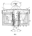
- Fig. 1 eine vorzugsweise zur Zertrümmerung von Konkrementen im Körper eines Patienten vorgesehene erfindungsgemäße Stoßwellenquelle in schematischer Darstellung im Längsschnitt, und
- Fig. 2 eine zur Behandlung von Tumorleiden vorgesehene erfinfindungsgemäße Stoßwellenquelle in schematischer Darstellung im Längsschnitt.
- 1 a shock wave source according to the invention, preferably provided for crushing concrements in the body of a patient, in a schematic illustration in longitudinal section, and
- 2 shows a shock wave source according to the invention intended for the treatment of tumor disorders in a schematic illustration in longitudinal section.
Die in Fig. 1 dargestellte Stoßwellenquelle besitzt eine im wesentlichen hohlzylindrische Membran 1 aus einem elektrisch leitenden Werkstoff, die als dünnwandiges, glattes, nahtloses Rohr konstanter Dicke ausgeführt ist. Die Membran 1 enthält wenigstens ein Material der Gruppe Aluminium, Kupfer, Silber oder deren Legierungen. Innerhalb der Membran 1 befindet sich eine Spule 2, die zylinderschraubenförmig auf einen zylindrischen Spulenträger 3 aus einem elektrisch isolierenden Werkstoff gewickelt ist. Die Spule 2 ist zur Vermeidung von Kurzschlüssen bzw. Spannungsüberschlägen zwischen ihren Windungen aus einem mit einer Lackisolierung versehenen Draht, vorzugsweise Kupferlackdraht, gewickelt. Die Windungen der Spule sind in nicht dargestellter Weise mittels eines geeigneten Tauch- bzw. Vergußharzes auf dem Spulenträger 3 fixiert. Um Spannungsüberschläge zwischen der Spule 2 und der Membran 1 zu vermeiden, die Spule 2 wird zur Erzeugung von Stoßwellen mit Hochspannungsimpulsen hoher Stromstärke beaufschlagt, ist die Spule 2 an ihrer äußeren Mantelfläche vollständig von einer Isolierfolie 4 umgeben, deren Dicke in der Fig. 1 wie auch die Dicke der Membran 1 und der Spule 2 übertrieben dargestellt ist.The shock wave source shown in Fig. 1 has an essentially hollow cylindrical membrane 1 made of an electrically conductive material, which is designed as a thin-walled, smooth, seamless tube of constant thickness. The membrane 1 contains at least one material from the group aluminum, copper, silver or their alloys. Inside the membrane 1 there is a
Der Spulenträger 3 weist an seiner äußeren Mantelfläche eine ringförmige Eindrehung 5 auf, in der die Spule 2 und die Isolierfolie 4 aufgenommen sind. Die Länge der Eindrehung 5 ist gleich der Länge der Spule 2. Die Tiefe der Eindrehung 5 ist gleich der Summe der Dicken der Spule 2 und der Isolierfolie 4 oder geringfügig größer als diese Summe. Der Spulenträger 3 weist also beiderseits der Spule 2 je einen zylindrischen Ansatz 6, 7 auf, wobei der Durchmesser der Ansätze 6, 7 im wesentlichen gleich dem Innendurchmesser der Membran 1 ist. Diese ist unter Zwischenfügung von in entsprechenden in den Ansätzen 6, 7 vorgesehenen Nuten 8, 9 aufgenommenen Dichtringen 10, 11 auf den Spulenträger 3 aufgesetzt. Mit Hilfe von Sprengringen 12, 13, die an den Enden der Membran 1 anliegen und in entsprechenden Nuten 14, 15 der Ansätze 6, 7 des Spulenträgers 3 aufgenommen sind, ist die Membran 1 auf dem Spulenträger 3 axial unverschieblich fixiert.The
Die Anschlüsse 16, 17 der Spule sind durch in dem Spulenträger 3 vorgesehene abgewinkelte Bohrungen 18, 19 zur Stirnfläche des Ansatzes 7 des Spulenträgers 3 geführt und mit einem schematisch angedeuteten Hochspannungs-Impulsgenerator 20 verbunden. Zwischen der Eindrehung 5 des Spulenträgers 3 und den die Dichtringe 10, 11 aufnehmenden Nuten 8, 9 ist jeweils eine weitere Nut 21, 22 vorgesehen. Die Nuten 21, 22 stehen über in dem Spulenträger 3 etwa radial verlaufende Bohrungen 23, 24 mit einer etwa axial in dem Spulenkörper 3 verlaufenden Bohrung 25 in Verbindung, welche im Bereich der Stirnfläche des Ansatzes 7 des Spulenträgers 3 endet und mittels einer Leitung 26 an eine in Fig. 1 schematisch angedeutete Vakuumpumpe 27 angeschlossen ist. Es ist so möglich, den zwischen der Innenwand der Membran 1 und der Isolierfolie 4 befindlichen Raum mit Unterdruck zu beaufschlagen.The
Außerdem besitzt die Stoßwellenquelle gemäß Fig. 1 ein topfförmiges Gehäuse 28 mit einem Boden 29 und einer zylinderrohrförmigen Wand 30. Der Spulenträger 3 ist mit seinem Ansatz 7 in einer Bohrung 31 des Bodens 29 des Gehäuses 28 unter Zwischenfügung eines Dichtringes 32 derart fixiert, daß die gemeinsame Mittelachse der Membran 1 und der Spule 2 mit der Mittelachse des Gehäuses 28 zusammenfällt.In addition, the shock wave source according to FIG. 1 has a pot-shaped
In dem Gehäuse 28 ist ein ringförmiger Reflektor 33 aufgenommen, dessen äußere Mantelfläche an der Innenseite der Wand 30 des Gehäuses 28 anliegt. Der Reflektor 33 liegt mit seiner einen Stirnfläche an dem Boden 29 des Gehäuses 28 an und ist mittels eines in einer entsprechenden in der Wand 30 des Gehäuses 28 vorgesehenen Nut 34 aufgenommenen Sprengringes 35 axial unverschieblich in dem Gehäuse 28 fixiert.An
An seinem offenen Ende ist das Gehäuse 28 mittels eines flexiblen Balges 36 verschlossen. Der gesamte von dem Balg 36, dem Gehäuse 28, dem Reflektor 33, dem Spulenträger 3 und der Membran 1 umschlossene Raum ist mit einem akustischen Ausbreitungsmedium 37, z.B. Wasser, gefüllt. Mittels des Balges 36 ist es möglich, die Stoßwellenquelle akustisch mit dem in Fig. 1 schematisch angedeuteten Körper 38 eines Patienten zu koppeln, indem die Stoßwellenquelle wie dargestellt mittels des Balges 36 an den Körper des Patienten angepreßt wird.At its open end, the
Der die Membran 1 umgebende ringförmige Reflektor 33 besitzt die Form eines Rotationsparaboloids, dessen Mittelachse mit der der Membran 1 und damit auch der der Spule 2 zusammenfällt. In anderen Worten ausgedrückt besitzt der Reflektor 33 eine konkave Reflektorfläche 39, die durch Rotation eines Abschnittes einer in Fig. 1 strichpunktiert angedeuteten Parabel P um die Mittelachse der Membran 1 erhalten wird, wobei der Brennpunkt F der Parabel P auf der Mittelachse der Membran 1 und der Scheitelpunkt S der Parabel P auf einer die Mittelachse der Membran 1 rechtwinklig schneidenden Geraden liegt. Dabei ist zu berücksichtigen, daß der Brennpunkt F der Parabel P im Betrieb der Stoßwellenquelle, wie noch erläutert werden wird, dem Zentrum des Fokusbereiches der erzeugten Stoßwellen entspricht. In der Regel ist die Erstreckung der Reflektorfläche 39 in Richtung der Mittelachse der Membran 1, wie in Fig. 1 dargestellt, gleich der Länge der Spule 2. In diesem Falle ist wie bei dem in Fig. 1 dargestellten Ausführungsbeispiel die Reflektorfläche 39 in axialer Richtung relativ zu der Spule 2 derart angeordnet ist, daß die einander entsprechenden Enden der Reflektorfläche 39 und der Spule 2 einander radial gegenüberliegen. Es ist jedoch grundsätzlich auch möglich, die Reflektorfläche 39 mit einer von der der Spule 2 abweichenden Erstreckung in Richtung der Mittelachse der Membran auszuführen und/oder die Reflektorfläche 39 relativ zu der Spule 2 axial versetzt anzuordnen. Der Reflektor 33 besteht aus einem Material, das akustisch härter als das Ausbreitungsmedium 37 ist. Wenn als Ausbreitungsmedium 37 Wasser vorgesehen ist, kommt als Material für den Reflektor 33 ein metallischer Werkstoff, beispielsweise Messing, in Frage. Dabei genügt es, wenn das genannte Material wie strichliert angedeutet wenigstens im Bereich der Reflektorfläche 39 des Reflektors 33 als ausreichend dicke Schicht vorhanden ist. Im Falle des Ausführungsbeispieles besteht der Reflektor 33 jedoch insgesamt aus dem genannten Material.The
Die Funktionsweise der Stoßwellenquelle gemäß Fig. 1 ist folgende:The mode of operation of the shock wave source according to FIG. 1 is as follows:
Wird die Spule 2 mittels des Hochspannungs-Impulsgenerators 20 mit einem Hochspannungsimpuls beaufschlagt, hat dies zur Folge, daß die Spule 2 äußerst schnell ein magnetisches Feld aufbaut. Hierdurch wird gleichzeitig in die Membran 1 ein Strom induziert, der dem in der Spule 2 fließenden Strom entgegengerichtet ist und demzufolge ein magnetisches Gegenfeld erzeugt, unter dessen Wirkung die Membran 1 schlagartig radial expandiert. Hierdurch wird von der Membran 1 in dem im Inneren der Stoßwellenquelle befindlichen Ausbreitungsmedium 37 ein sich radial auswärts ausbreitender Druckimpuls in der Gestalt einer Zylinderwelle erzeugt, der, so wie dies für die "Randstrahlen" der Zylinderwelle in Fig. 1 strichliert angedeutet ist, an der rotationsparaboloidförmigen Reflektorfläche des Reflektors 33 derart reflektiert wird, daß er in dem Brennpunkt F der Parabel P zusammenläuft. Auf seinem Ausbreitungsweg geht der Druckimpuls, der sich infolge der nicht-linearen Kompressionseigenschaften des Ausbreitungsmediums 37 allmählich aufsteilt, in eine Stoßwelle über. Es wird also deutlich, daß die Stoßwellenquelle gemäß Fig. 1 Stoßwellen erzeugt, die in einem Fokusbereich zusammenlaufen, dessen Zentrum dem Brennpunkt F der Parabel P entspricht. Bei den so erzeugten Stoßwellen handelt es sich infolge des Umstandes, daß der Reflektor 33 aus einem Material gebildet ist, das akustisch härter als das Ausbreitungsmedium 37 ist, - unter einer größeren akustischen Härte versteht man, daß der akustische Wellenwiderstand dieses Materials größer als der des Ausbreitungsmediums ist, - um Stoßwellen in Form von Druckimpulsen.If a high-voltage pulse is applied to the
Während der Erzeugung von Stoßwellen wird der zwischen der Membran 1 und der Isolierfolie 4 befindliche Raum über die Leitung 26 und die Bohrungen 23, 24, 25 mittels der Vakuumpumpe 27 mit Unterdruck beaufschlagt, um einerseits im Interesse eines hohen Wirkungsgrades der Stoßwellenquelle sicherzustellen, daß sich die Membran 1 vor Beaufschlagung der Spule 2 mit einem Hochspannungsimpuls möglichst nahe bei der Spule 2 befindet, und andererseits zu gewährleisten, daß die Membran 1 nach erfolgter Abgabe eines Druckimpulses in eine definierte Ausgangslage zurückkehrt.During the generation of shock waves, the space between the membrane 1 and the insulating film 4 via the
Um im Körper 38 eines Patienten befindliche Konkremente, in Fig. 1 ist schematisch der Stein 40 einer Niere 41 angedeutet, zertrümmern zu können, wird die Stoßwellenquelle mittels des flexiblen Balges 36 an die Körperoberfläche des Patienten zur akustischen Koppelung angepreßte Stoßwellenquelle derart ausgerichtet, daß sich das zu zertrümmernde Konkrement 40, so wie dies in Fig. 1 dargestellt ist, im Brennpunkt F der Parabel P und damit im Fokusbereich der Stoßwellen befindet. Unter der Wirkung einer Anzahl von aufeinanderfolgend erzeugter Stoßwel len zerfällt das Konkrement 40 dann in Bruchstücke, die auf natürlichem Wege abgehen können.In order to be able to shatter concrements located in the
Um die Stoßwellenquelle in der beschriebenen Weise relativ zu dem Körper 38 des Patienten ausrichten zu können, ist in einer zentralen Bohrung 42 des Spulenträgers 3 eine in Fig. 1 nur schematisch angedeutete Ultraschall-Ortungseinrichtung 43 angeordnet, die über ein Kabel 44 mit einer nicht dargestellten Steuerungs- und Bilderzeugungselektronik in Verbindung steht und es gestattet, den Fokusbereich der Stoßwellen abzubilden. Vorzugsweise handelt es sich bei der Ultraschall-Ortungseinrichtung um einen an sich bekannten Ultraschall-Sektorscanner, der so angeordnet ist, daß eine die Mittelachse der Membran 1 und damit den Fokusbereich der Stoßwellen enthaltende kreissektorförmige Schicht des Körpers 38 des Patienten abtastbar ist.In order to be able to align the shock wave source relative to the patient's
Ein im wesentlichen gemäß Fig. 1 ausgeführter Prototyp einer erfindungsgemäßen Stoßwellenquelle besitzt eine Aluminium-Membran mit einem Außendurchmesser von 56 mm, einer Dicke von 0,3 mm und einer Länge von 60 mm. Die Spule des Prototyps ist aus einem Draht kreisförmigen Querschnitts mit einem Durchmesser von 0,5 mm auf einen Spulenträger aus Hartgewebe gewickelt, und weist drei parallelgeschaltete Wicklungen zu je 29 Windungen auf. Der Reflektor ist auf Grundlage einer Parabel zweiter Ordnung mit einem Halbparameter von 200 mm ausgebildet und besitzt an seinem dem Brennpunkt der Parabel zugewandten Ende einen Innendurchmesser von 168 mm und an seinem anderen Ende einen Innendurchmesser von 118 mm. Der Abstand des Brennpunktes von der Vorderkante des Reflektors beträgt 80 mm. Der Reflektor des Prototyps besteht aus Messing. Als Ausbreitungsmedium fand bei dem Prototypen Wasser Verwendung.A prototype of a shock wave source according to the invention, essentially as shown in FIG. 1, has an aluminum membrane with an outer diameter of 56 mm, a thickness of 0.3 mm and a length of 60 mm. The coil of the prototype is wound from a wire of circular cross-section with a diameter of 0.5 mm on a coil carrier made of hard tissue, and has three windings connected in parallel, each with 29 turns. The reflector is designed on the basis of a second-order parabola with a half parameter of 200 mm and has an inner diameter of 168 mm at its end facing the focal point of the parabola and an inner diameter of 118 mm at its other end. The distance of the focal point from the front edge of the reflector is 80 mm. The prototype's reflector is made of brass. Water was used as the propagation medium in the prototype.
In der Fig. 2 ist eine weitere Ausführungsform der erfindungsgemäßen Stoßwellenquelle dargestellt, die insbesondere zur Beschallung pathologischer Gewebeveränderungen, z.B. eines im Körper 38 eines Patienten befindlichen Tumors 45, dient. Die Stoßwellenquelle gemäß Fig. 2 unterscheidet sich von dem zuvor beschriebenen Ausführungsbeispiel lediglich durch ein unterschiedliches Material des die Reflektorfläche 46 aufweisenden Reflektors 47, weshalb die übrigen Elemente der Stoßwellenquelle gemäß Fig. 2 die gleichen Bezugszeichen wie in Fig. 1 tragen.FIG. 2 shows a further embodiment of the shock wave source according to the invention, which is used in particular for sonicating pathological tissue changes, for example a
Im Gegensatz zu dem zuvor beschriebenen Ausführungsbeispiel besteht im Falle der Fig. 2 der Reflektor 47 aus einem Material, das akustisch weicher als das Ausbreitungsmedium 37 ist. Wenn als Ausbreitungsmedium 37 Wasser vorgesehen ist, kommt als Material für den Reflektor 47 insbesondere ein Schaumstoff mit geschlossenen Poren wie z.B. Polyurethanschaum in Frage. Dabei genügt es, wenn dieses Material wenigstens im Bereich der Reflektorfläche 46 des Reflektors 47 wie strichliert angedeutet als ausreichend dicke Schicht vorhanden ist. Im Falle des dargestellten Ausführungsbeispieles besteht der Reflektor jedoch insgesamt aus dem Schaumstoff mit geschlossenen Poren.In contrast to the exemplary embodiment described above, in the case of FIG. 2, the
In ihrer Funktionsweise unterscheidet sich die Stoßwellenquelle gemäß Fig. 2 von der zuvor beschriebenen insofern, als infolge des Umstandes, daß der Reflektor 47 aus einem Material besteht, das akustisch weicher als das Ausbreitungsmedium 37 ist, - hierunter versteht man, daß der akustische Wellenwiderstand dieses Materials kleiner als der des Übertragungsmediums ist, - Stoßwellen in Form von Unterdruckimpulsen erzeugt werden. Der Grund für diese unterschiedliche Funktionsweise liegt darin, daß bei Reflexionen an einer schallweichen Grenzschicht eine Phasenumkehr stattfindet (Reflexionsfaktor ist negativ). Eine Beschallung von Tumoren mit Stoßwellen in Form von Unterdruckimpulsen ist aus den bereits erläuterten Gründen einer Beschallung mit Stoßwellen in Form von Druckimpulsen vorzuziehen.The functioning of the shock wave source according to FIG. 2 differs from that described above in that due to the fact that the
Im Falle des beschriebenen Ausführungsbeispieles ist lediglich eine einzige zylinderschraubenförmig gewickelte Spule 2 vorhanden. Es können aber auch mehrere solcher Spulen vorhanden sein, die beispielsweise axial aufeinanderfolgend auf den Spulen körper 3 gewickelt sind. In Abhängigkeit von der Anzahl der Spulen, die mit dem zur Erzeugung einer Stoßwelle dienenden Hochspannungsimpuls beaufschlagt werden, können dann Stoßwellen unterschiedlicher Intensität erzeugt werden.In the case of the exemplary embodiment described, there is only a
Die Reflektorfläche 39 bzw. 46 muß nicht exakt rotationsparaboloidförmig ausgebildet sein, sondern kann auch durch Rotation eines Abschnittes eines Kreises, einer Ellipse oder dergleichen erhalten werden, sofern die Wirkung der so erhaltenen Reflektorfläche von der einer rotationsparaboloidförmigen nicht wesentlich abweicht.The
Claims (13)
Priority Applications (3)
| Application Number | Priority Date | Filing Date | Title |
|---|---|---|---|
| EP89114925A EP0412202A1 (en) | 1989-08-11 | 1989-08-11 | Shock wave generator to produce focused shock waves with a reflector shaped as a paraboloid of revolution |
| US07/558,095 US5058569A (en) | 1989-08-11 | 1990-07-26 | Apparatus for generating focused shockwaves having a cylindrical coil and a paraboloid of revolution reflector |
| JP2210143A JPH0377549A (en) | 1989-08-11 | 1990-08-07 | Shock wave source for generation of focusing shock wave |
Applications Claiming Priority (1)
| Application Number | Priority Date | Filing Date | Title |
|---|---|---|---|
| EP89114925A EP0412202A1 (en) | 1989-08-11 | 1989-08-11 | Shock wave generator to produce focused shock waves with a reflector shaped as a paraboloid of revolution |
Publications (1)
| Publication Number | Publication Date |
|---|---|
| EP0412202A1 true EP0412202A1 (en) | 1991-02-13 |
Family
ID=8201759
Family Applications (1)
| Application Number | Title | Priority Date | Filing Date |
|---|---|---|---|
| EP89114925A Ceased EP0412202A1 (en) | 1989-08-11 | 1989-08-11 | Shock wave generator to produce focused shock waves with a reflector shaped as a paraboloid of revolution |
Country Status (3)
| Country | Link |
|---|---|
| US (1) | US5058569A (en) |
| EP (1) | EP0412202A1 (en) |
| JP (1) | JPH0377549A (en) |
Cited By (4)
| Publication number | Priority date | Publication date | Assignee | Title |
|---|---|---|---|---|
| DE3835318C1 (en) * | 1988-10-17 | 1990-06-28 | Storz Medical Ag, Kreuzlingen, Ch | |
| DE10360942A1 (en) * | 2003-12-23 | 2005-08-04 | Switech Invest Ag | Device for treating bones and / or soft tissues of the human or animal body and / or for modifying cells and tissues by means of extracorporeal shock waves and using the device |
| DE102006002418A1 (en) * | 2006-01-18 | 2007-07-19 | Switech Medical Ag | Reflector for shock wave generator, has two electrodes and spark discharge section, where reflector is built from corrosion resistant, non-metallic material, and has ellipsoid or paraboloid form |
| EP2529678A1 (en) * | 2011-05-31 | 2012-12-05 | Storz Medical Ag | Pressure wave device for treating the human or animal body |
Families Citing this family (15)
| Publication number | Priority date | Publication date | Assignee | Title |
|---|---|---|---|---|
| DE9109025U1 (en) * | 1990-08-02 | 1991-12-05 | Siemens Ag, 8000 Muenchen, De | |
| DE4110102A1 (en) * | 1991-03-27 | 1992-10-01 | Siemens Ag | Electromagnetically driven pressure pulse source for medical use - has electrically conducting membrane formed as annular array of zones activated by drive coils having variable timings |
| DE4125950C1 (en) * | 1991-08-06 | 1992-11-05 | Dornier Medizintechnik Gmbh, 8000 Muenchen, De | |
| US5240002A (en) * | 1992-03-23 | 1993-08-31 | Bantum Tripter Joint Venture Partners | Ultrasound transducer shielding |
| US5203334A (en) * | 1992-03-23 | 1993-04-20 | B&L Technologies, Inc. | Transducer mounting in lithotripter |
| US5393296A (en) * | 1992-12-09 | 1995-02-28 | Siemens Aktiengesellschaft | Method for the medical treatment of pathologic bone |
| US7189209B1 (en) * | 1996-03-29 | 2007-03-13 | Sanuwave, Inc. | Method for using acoustic shock waves in the treatment of a diabetic foot ulcer or a pressure sore |
| US6869407B2 (en) * | 2001-09-12 | 2005-03-22 | Moshe Ein-Gal | Acoustic wave device |
| US7048699B2 (en) * | 2001-09-12 | 2006-05-23 | Moshe Ein-Gal | Non-cylindrical acoustic wave device |
| US7559904B2 (en) * | 2003-07-17 | 2009-07-14 | Moshe Ein-Gal | Shockwave generating system |
| US20070239074A1 (en) * | 2006-02-15 | 2007-10-11 | Moshe Ein-Gal | Line focusing acoustic wave source |
| EP2467071B1 (en) | 2009-08-19 | 2019-09-18 | Duke University | Acoustic lens for shockwave lithotripsy |
| US9913748B2 (en) | 2009-10-30 | 2018-03-13 | Avner Spector | Method and apparatus for treatment of erectile dysfunction with extracorporeal shockwaves |
| WO2016095876A1 (en) | 2014-12-19 | 2016-06-23 | Univerzita Karlova V Praze | Shockwave applicator and a shockwave application system |
| EP3682822A1 (en) | 2019-01-18 | 2020-07-22 | Storz Medical AG | Combined shockwave and ultrasound source |
Citations (2)
| Publication number | Priority date | Publication date | Assignee | Title |
|---|---|---|---|---|
| FR2440227A1 (en) * | 1978-10-31 | 1980-05-30 | Onera (Off Nat Aerospatiale) | Electrodynamic vibrator for aircraft industry - has flat radial aluminium blades attached to central cylindrical section and with cut=outs for supporting moving coil assembly |
| DE3727692A1 (en) * | 1987-08-19 | 1989-03-02 | Siemens Ag | Shock wave source with short focussing |
Family Cites Families (7)
| Publication number | Priority date | Publication date | Assignee | Title |
|---|---|---|---|---|
| DE3328051A1 (en) * | 1983-08-03 | 1985-02-14 | Siemens AG, 1000 Berlin und 8000 München | DEVICE FOR CONTACTLESS CRUSHING OF CONCRETE |
| DE3443295A1 (en) * | 1984-11-28 | 1986-06-05 | Wolfgang Prof. Dr. 7140 Ludwigsburg Eisenmenger | DEVICE FOR THE CONTACT-FREE CRUSHING OF CONCRETE IN THE BODY OF LIVING BEINGS |
| DE3447440A1 (en) * | 1984-12-27 | 1986-07-03 | Siemens AG, 1000 Berlin und 8000 München | SHOCK SHAFT PIPE FOR THE CRUSHING OF CONCRETE |
| SU1393489A1 (en) * | 1986-02-19 | 1988-05-07 | Опытно-конструкторское бюро "Горизонт" | Acoustic focusing converter |
| SU1405885A2 (en) * | 1986-05-27 | 1988-06-30 | Опытно-конструкторское бюро "Горизонт" | Acoustic focusing transducer |
| DE8709363U1 (en) * | 1987-07-07 | 1988-11-03 | Siemens Ag, 1000 Berlin Und 8000 Muenchen, De | |
| DE8717503U1 (en) * | 1987-10-19 | 1988-12-22 | Siemens Ag, 1000 Berlin Und 8000 Muenchen, De |
-
1989
- 1989-08-11 EP EP89114925A patent/EP0412202A1/en not_active Ceased
-
1990
- 1990-07-26 US US07/558,095 patent/US5058569A/en not_active Expired - Fee Related
- 1990-08-07 JP JP2210143A patent/JPH0377549A/en active Pending
Patent Citations (2)
| Publication number | Priority date | Publication date | Assignee | Title |
|---|---|---|---|---|
| FR2440227A1 (en) * | 1978-10-31 | 1980-05-30 | Onera (Off Nat Aerospatiale) | Electrodynamic vibrator for aircraft industry - has flat radial aluminium blades attached to central cylindrical section and with cut=outs for supporting moving coil assembly |
| DE3727692A1 (en) * | 1987-08-19 | 1989-03-02 | Siemens Ag | Shock wave source with short focussing |
Cited By (4)
| Publication number | Priority date | Publication date | Assignee | Title |
|---|---|---|---|---|
| DE3835318C1 (en) * | 1988-10-17 | 1990-06-28 | Storz Medical Ag, Kreuzlingen, Ch | |
| DE10360942A1 (en) * | 2003-12-23 | 2005-08-04 | Switech Invest Ag | Device for treating bones and / or soft tissues of the human or animal body and / or for modifying cells and tissues by means of extracorporeal shock waves and using the device |
| DE102006002418A1 (en) * | 2006-01-18 | 2007-07-19 | Switech Medical Ag | Reflector for shock wave generator, has two electrodes and spark discharge section, where reflector is built from corrosion resistant, non-metallic material, and has ellipsoid or paraboloid form |
| EP2529678A1 (en) * | 2011-05-31 | 2012-12-05 | Storz Medical Ag | Pressure wave device for treating the human or animal body |
Also Published As
| Publication number | Publication date |
|---|---|
| JPH0377549A (en) | 1991-04-03 |
| US5058569A (en) | 1991-10-22 |
Similar Documents
| Publication | Publication Date | Title |
|---|---|---|
| EP0412202A1 (en) | Shock wave generator to produce focused shock waves with a reflector shaped as a paraboloid of revolution | |
| EP0386479B1 (en) | Shock wave generator | |
| DE4117638C2 (en) | ||
| EP0369177B1 (en) | Focused acoustic pressure wave generator | |
| DE3312014C2 (en) | Device for the contact-free crushing of concretions in the body of living beings | |
| DE4213586C2 (en) | Therapy device for treatment with focused acoustic waves | |
| DE3319871C2 (en) | ||
| EP0327917B1 (en) | Shock wave generator for the non-contacting disintegration of concretions in a body | |
| DE4110102C2 (en) | ||
| DE3390293T1 (en) | Ultrasonic transducer | |
| DE3328051A1 (en) | DEVICE FOR CONTACTLESS CRUSHING OF CONCRETE | |
| DE3328039C2 (en) | FACILITIES FOR THE CONTACTLESS SMASHING OF A CONCERMENT IN THE BODY OF A LIVING BEING | |
| EP0133946A2 (en) | Apparatus for the contactless disintegration of concrements | |
| EP0254104B1 (en) | Shock-wave generator for producing an acoustic shock-wave pulse | |
| WO2007128611A1 (en) | Shock wave head for a shock wave treatment apparatus and method for the fragmentation of and for controlling the fragmentation of a fragmentation object arranged in an object under investigation | |
| DE3727692C2 (en) | Shock wave source with short focus | |
| DE4123160C1 (en) | ||
| EP0240797B1 (en) | Shockwave generator with increased efficiency | |
| DE4039408A1 (en) | Shock wave generator with reflector - has several reflector sections, each associated with different focus zone enabling rapid focus zone displacement | |
| DE3739393C2 (en) | Lithotripter with adjustable focus | |
| DE3739390A1 (en) | Lithotripter having a variable focus | |
| DE4102447C1 (en) | ||
| EP0461287A1 (en) | Electrically-driven acoustic shock-wave generator | |
| DE4039410A1 (en) | Shock wave generator for generating focussed shock waves - has acoustic lens between pressure pulse source and reflector surface enabling rapid focus zone displacement | |
| DE3703338A1 (en) | Lithotripter with an integrated locating device |
Legal Events
| Date | Code | Title | Description |
|---|---|---|---|
| PUAI | Public reference made under article 153(3) epc to a published international application that has entered the european phase |
Free format text: ORIGINAL CODE: 0009012 |
|
| 17P | Request for examination filed |
Effective date: 19901205 |
|
| AK | Designated contracting states |
Kind code of ref document: A1 Designated state(s): DE FR GB NL |
|
| 17Q | First examination report despatched |
Effective date: 19930902 |
|
| APAB | Appeal dossier modified |
Free format text: ORIGINAL CODE: EPIDOS NOAPE |
|
| APAA | Appeal reference recorded |
Free format text: ORIGINAL CODE: EPIDOS REFN |
|
| APAB | Appeal dossier modified |
Free format text: ORIGINAL CODE: EPIDOS NOAPE |
|
| STAA | Information on the status of an ep patent application or granted ep patent |
Free format text: STATUS: THE APPLICATION HAS BEEN REFUSED |
|
| 18R | Application refused |
Effective date: 19990712 |
|
| APAF | Appeal reference modified |
Free format text: ORIGINAL CODE: EPIDOSCREFNE |