EP0411961A2 - Appareil d'enregistrement/de reproduction de disque optique - Google Patents
Appareil d'enregistrement/de reproduction de disque optique Download PDFInfo
- Publication number
- EP0411961A2 EP0411961A2 EP90308577A EP90308577A EP0411961A2 EP 0411961 A2 EP0411961 A2 EP 0411961A2 EP 90308577 A EP90308577 A EP 90308577A EP 90308577 A EP90308577 A EP 90308577A EP 0411961 A2 EP0411961 A2 EP 0411961A2
- Authority
- EP
- European Patent Office
- Prior art keywords
- reproduced
- recording
- optical disk
- reproduced signals
- recorded information
- Prior art date
- Legal status (The legal status is an assumption and is not a legal conclusion. Google has not performed a legal analysis and makes no representation as to the accuracy of the status listed.)
- Granted
Links
Images


Classifications
-
- G—PHYSICS
- G11—INFORMATION STORAGE
- G11B—INFORMATION STORAGE BASED ON RELATIVE MOVEMENT BETWEEN RECORD CARRIER AND TRANSDUCER
- G11B7/00—Recording or reproducing by optical means, e.g. recording using a thermal beam of optical radiation by modifying optical properties or the physical structure, reproducing using an optical beam at lower power by sensing optical properties; Record carriers therefor
-
- H—ELECTRICITY
- H04—ELECTRIC COMMUNICATION TECHNIQUE
- H04N—PICTORIAL COMMUNICATION, e.g. TELEVISION
- H04N5/00—Details of television systems
- H04N5/76—Television signal recording
- H04N5/91—Television signal processing therefor
- H04N5/92—Transformation of the television signal for recording, e.g. modulation, frequency changing; Inverse transformation for playback
- H04N5/9201—Transformation of the television signal for recording, e.g. modulation, frequency changing; Inverse transformation for playback involving the multiplexing of an additional signal and the video signal
- H04N5/9202—Transformation of the television signal for recording, e.g. modulation, frequency changing; Inverse transformation for playback involving the multiplexing of an additional signal and the video signal the additional signal being a sound signal
-
- G—PHYSICS
- G11—INFORMATION STORAGE
- G11B—INFORMATION STORAGE BASED ON RELATIVE MOVEMENT BETWEEN RECORD CARRIER AND TRANSDUCER
- G11B19/00—Driving, starting, stopping record carriers not specifically of filamentary or web form, or of supports therefor; Control thereof; Control of operating function ; Driving both disc and head
- G11B19/20—Driving; Starting; Stopping; Control thereof
- G11B19/24—Arrangements for providing constant relative speed between record carrier and head
- G11B19/247—Arrangements for providing constant relative speed between record carrier and head using electrical means
-
- G—PHYSICS
- G11—INFORMATION STORAGE
- G11B—INFORMATION STORAGE BASED ON RELATIVE MOVEMENT BETWEEN RECORD CARRIER AND TRANSDUCER
- G11B27/00—Editing; Indexing; Addressing; Timing or synchronising; Monitoring; Measuring tape travel
- G11B27/02—Editing, e.g. varying the order of information signals recorded on, or reproduced from, record carriers
- G11B27/031—Electronic editing of digitised analogue information signals, e.g. audio or video signals
- G11B27/036—Insert-editing
-
- G—PHYSICS
- G11—INFORMATION STORAGE
- G11B—INFORMATION STORAGE BASED ON RELATIVE MOVEMENT BETWEEN RECORD CARRIER AND TRANSDUCER
- G11B27/00—Editing; Indexing; Addressing; Timing or synchronising; Monitoring; Measuring tape travel
- G11B27/10—Indexing; Addressing; Timing or synchronising; Measuring tape travel
- G11B27/102—Programmed access in sequence to addressed parts of tracks of operating record carriers
- G11B27/105—Programmed access in sequence to addressed parts of tracks of operating record carriers of operating discs
-
- G—PHYSICS
- G11—INFORMATION STORAGE
- G11B—INFORMATION STORAGE BASED ON RELATIVE MOVEMENT BETWEEN RECORD CARRIER AND TRANSDUCER
- G11B27/00—Editing; Indexing; Addressing; Timing or synchronising; Monitoring; Measuring tape travel
- G11B27/10—Indexing; Addressing; Timing or synchronising; Measuring tape travel
- G11B27/11—Indexing; Addressing; Timing or synchronising; Measuring tape travel by using information not detectable on the record carrier
-
- G—PHYSICS
- G11—INFORMATION STORAGE
- G11B—INFORMATION STORAGE BASED ON RELATIVE MOVEMENT BETWEEN RECORD CARRIER AND TRANSDUCER
- G11B27/00—Editing; Indexing; Addressing; Timing or synchronising; Monitoring; Measuring tape travel
- G11B27/10—Indexing; Addressing; Timing or synchronising; Measuring tape travel
- G11B27/19—Indexing; Addressing; Timing or synchronising; Measuring tape travel by using information detectable on the record carrier
- G11B27/24—Indexing; Addressing; Timing or synchronising; Measuring tape travel by using information detectable on the record carrier by sensing features on the record carrier other than the transducing track ; sensing signals or marks recorded by another method than the main recording
-
- G—PHYSICS
- G11—INFORMATION STORAGE
- G11B—INFORMATION STORAGE BASED ON RELATIVE MOVEMENT BETWEEN RECORD CARRIER AND TRANSDUCER
- G11B27/00—Editing; Indexing; Addressing; Timing or synchronising; Monitoring; Measuring tape travel
- G11B27/10—Indexing; Addressing; Timing or synchronising; Measuring tape travel
- G11B27/19—Indexing; Addressing; Timing or synchronising; Measuring tape travel by using information detectable on the record carrier
- G11B27/28—Indexing; Addressing; Timing or synchronising; Measuring tape travel by using information detectable on the record carrier by using information signals recorded by the same method as the main recording
- G11B27/32—Indexing; Addressing; Timing or synchronising; Measuring tape travel by using information detectable on the record carrier by using information signals recorded by the same method as the main recording on separate auxiliary tracks of the same or an auxiliary record carrier
- G11B27/327—Table of contents
- G11B27/329—Table of contents on a disc [VTOC]
-
- G—PHYSICS
- G11—INFORMATION STORAGE
- G11B—INFORMATION STORAGE BASED ON RELATIVE MOVEMENT BETWEEN RECORD CARRIER AND TRANSDUCER
- G11B7/00—Recording or reproducing by optical means, e.g. recording using a thermal beam of optical radiation by modifying optical properties or the physical structure, reproducing using an optical beam at lower power by sensing optical properties; Record carriers therefor
- G11B7/004—Recording, reproducing or erasing methods; Read, write or erase circuits therefor
-
- H—ELECTRICITY
- H04—ELECTRIC COMMUNICATION TECHNIQUE
- H04N—PICTORIAL COMMUNICATION, e.g. TELEVISION
- H04N5/00—Details of television systems
- H04N5/76—Television signal recording
- H04N5/84—Television signal recording using optical recording
- H04N5/85—Television signal recording using optical recording on discs or drums
-
- G—PHYSICS
- G11—INFORMATION STORAGE
- G11B—INFORMATION STORAGE BASED ON RELATIVE MOVEMENT BETWEEN RECORD CARRIER AND TRANSDUCER
- G11B2220/00—Record carriers by type
- G11B2220/20—Disc-shaped record carriers
- G11B2220/21—Disc-shaped record carriers characterised in that the disc is of read-only, rewritable, or recordable type
- G11B2220/215—Recordable discs
- G11B2220/216—Rewritable discs
-
- G—PHYSICS
- G11—INFORMATION STORAGE
- G11B—INFORMATION STORAGE BASED ON RELATIVE MOVEMENT BETWEEN RECORD CARRIER AND TRANSDUCER
- G11B2220/00—Record carriers by type
- G11B2220/20—Disc-shaped record carriers
- G11B2220/21—Disc-shaped record carriers characterised in that the disc is of read-only, rewritable, or recordable type
- G11B2220/215—Recordable discs
- G11B2220/218—Write-once discs
-
- G—PHYSICS
- G11—INFORMATION STORAGE
- G11B—INFORMATION STORAGE BASED ON RELATIVE MOVEMENT BETWEEN RECORD CARRIER AND TRANSDUCER
- G11B2220/00—Record carriers by type
- G11B2220/20—Disc-shaped record carriers
- G11B2220/25—Disc-shaped record carriers characterised in that the disc is based on a specific recording technology
- G11B2220/2525—Magneto-optical [MO] discs
-
- G—PHYSICS
- G11—INFORMATION STORAGE
- G11B—INFORMATION STORAGE BASED ON RELATIVE MOVEMENT BETWEEN RECORD CARRIER AND TRANSDUCER
- G11B2220/00—Record carriers by type
- G11B2220/20—Disc-shaped record carriers
- G11B2220/25—Disc-shaped record carriers characterised in that the disc is based on a specific recording technology
- G11B2220/2537—Optical discs
- G11B2220/2545—CDs
-
- G—PHYSICS
- G11—INFORMATION STORAGE
- G11B—INFORMATION STORAGE BASED ON RELATIVE MOVEMENT BETWEEN RECORD CARRIER AND TRANSDUCER
- G11B2220/00—Record carriers by type
- G11B2220/60—Solid state media
- G11B2220/65—Solid state media wherein solid state memory is used for storing indexing information or metadata
-
- G—PHYSICS
- G11—INFORMATION STORAGE
- G11B—INFORMATION STORAGE BASED ON RELATIVE MOVEMENT BETWEEN RECORD CARRIER AND TRANSDUCER
- G11B27/00—Editing; Indexing; Addressing; Timing or synchronising; Monitoring; Measuring tape travel
- G11B27/02—Editing, e.g. varying the order of information signals recorded on, or reproduced from, record carriers
- G11B27/031—Electronic editing of digitised analogue information signals, e.g. audio or video signals
- G11B27/034—Electronic editing of digitised analogue information signals, e.g. audio or video signals on discs
Definitions
- the present invention relates to an optical disk recording/reproducing device that records and/or reproduces information while performing a control such that a so-called Write-Once type or Rewritable type optical disk is rotated in Constant Linear Velocity.
- CDs compact disks
- audio information or other information is recorded in the form of digital signals through minute pits that can be detected optically
- the information recorded on a CD is reproduced by means of a Read-Only optical disk recording/reproducing device.
- a plurality of pieces of information are usually recorded in succession.
- absolute addresses that provide information concerning recording/reproducing positions on the disk are preliminary recorded on the disk in the form of physical alterations.
- absolute addresses read from the disk and absolute addresses indicating the recording start position of each piece of information and recorded in a TOC (Table Of Contents) area provided in the inner periphery or other location of the disk are compared, and the desired pieces of information may be reproduced successively or selectively.
- An optical disk recording/reproducing device that records and reproduces audio information or other information on rewritable optical disks developed recently such as magneto-optical disks or Write-Once type optical disks where information can be recorded only once, should preferably adopt the same method of reproduction as the one used in a conventional optical disk recording/reproducing device for CDs only and should be able to be employed compatibly with the different types of optical disks in use.
- a so-called Constant Linear Velocity (hereinafter referred to CLV) that is employed with CDs may be adopted as rotation control method for the optical disk during the recording and the reproduction.
- the CLV method may be implemented by for example controlling the rotational speed of a motor in accordance with the radial position of an optical head.
- the rotational speed of the motor is detected by means of a rotary encoder or other member, and the radial position of the optical head is detected by means of a position detecting sensor.
- a rotation control that is sufficiently accurate cannot be expected as errors occur in, for instance, the detections performed by the rotary encoder and the position detecting sensor.
- the accuracy of the rotation control may be improved by enforcing the CLV method according to disk position information that was preliminary recorded on the optical disk such as the absolute addresses described above.
- disk position information that was preliminary recorded on the optical disk such as the absolute addresses described above.
- Japanese Publication for Unexamined Patent Application 1989-39632 discloses a method for recording absolute addresses. Namely, the disk position information goes through a Biphasemark modulation process and the guiding groove of the optical disk is made to deviate inward or outward in a radial direction or the width of the guiding groove is changed, depending on whether the modulated code is "1" or "0".
- the absolute addresses and the recorded information can be reproduced separately by having their respective frequency bandwidths differ from each other.
- An object of the present invention is to provide an optical disk recording/reproducing device where the rotation control in Constant Linear Velocity of an optical disk, may be executed based on the reproduced signals of pre-recorded information that was preliminary recorded on the optical disk, during the reproduction when a rotation control based on the reproduced signals of recorded information is infeasible.
- an optical disk recording/reproducing device in accordance with the present invention is characterized in comprising control means for performing the rotation control of an optical disk in Constant Linear Velocity such that: during the recording, the rotation control is executed according to reproduced signals of pre-recorded information that was recorded on the optical disk preliminary, during the reproduction, the rotation control is executed according to reproduced signals of recorded information, and when the rotation control based on the reproduced signals of the recorded information is infeasible, the rotation control is switched and executed according to the reproduced signals of the pre-recorded information during the reproduction also.
- the rotation control in Constant Linear Velocity (CLV) is performed according to the reproduced signals of the pre-recorded information during the recording, and according to the reproduced signals of the recorded information during the reproduction.
- CLV Constant Linear Velocity
- Fig. 1 to Fig 6 illustrate a first embodiment of the present invention.
- Fig. 8 to Fig. 11 illustrate a third embodiment.
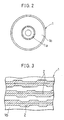
- a magneto-optical disk 1 as a rewritable optical disk is accommodated with a TOC (Table Of Contents) area 1a located in the inner periphery, as well as with an information recording area lb occupying most of the area outside the TOC area 1a.
- TOC Table Of Contents
- Different types of information such as music programs or other data, are recorded in the information recording area 1b while additional information concerning the different pieces of information recorded in the information recording area lb, is recorded in the TOC area 1a.
- the additional information might consist for example of absolute addresses indicating the recording start position and absolute addresses indicating the recording end position of each information.
- a guiding groove 2 of a spiral shape is preliminary formed in the TOC area 1a and the information recording area 1b of the magneto-optical disk 1 and circles at predetermined intervals in a radial direction.
- the guiding groove 2 may also be composed of concentric circles.
- the guiding groove 2 is used for the tracking control during the recording and the reproduction.
- the guiding groove 2 is made to deviate inward or outward in a radial direction depending of whether the modulated codes obtained after the absolute addresses provided on the disk went through a Biphasemark modulation process, are "1" or "0".
- the above absolute addresses form pre-recorded information to be used as rotation control information.
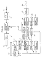
- the optical disk recording/reproducing device of the present embodiment comprises a spindle motor 3, as driving means for supporting and driving the magneto-optical disk 1 to rotate, an optical head 4 that projects a laser beam on the magneto-optical disk 1 during the recording and the reproduction, and a coil 5 that applies a magnetic field on the magneto-optical disk 1 during recording.
- the present optical disk recording/reproducing device adopts a magnetic modulation method as method for recording information and is capable of overwriting by recording new information over information already recorded.
- the optical disk recording/reproducing device includes an input terminal 6 where the information to be recorded is entered to.
- An analog information that was entered through tile input terminal 6 is converted into a digital signal in an A/D (analog/digital) converter 7, goes through a prescribed EFM (Eight to Fourteen Modulation) process in a recording signal processing circuit 8, and is fed into a coil driver 10.
- the signal is recorded as the coil driver 10 drives the coil 5 in response to the signal that was fed thereto, while at the same time a laser beam is projected from the optical head 4 and is irradiated on the magneto-optical disk 1.
- Fig. 5 shows the frame format of signals used in a CD.
- An information "a" of one frame is composed of a data field “d” comprising an audio information or other information of 24 bytes and an error correction parity of 8 bytes added thereto, a sub code “c” indicating the number of the piece of music, the time and other information about the audio information, and a synchronizing signal "b” appended to each frame and indicating the leading edge of the frame.
- Pieces of information "a" of one frame are recorded in succession.
- Sub codes "c" comprised in the pieces of additional information recorded in the TOC area 1a further include at least information concerning the recording end position of each information, or information indicating the recording time from the recording start position to the recording end position of each information recorded according to the above frame format.
- a signal that was reproduced by means of the optical head 4 is amplified by a reproduction amplifier 11.
- the signal that was amplified is sent to a pre-recorded information detecting circuit 12 and to a reproduced signal processing circuit 16.
- the pre-recorded information detecting circuit 12 is for example composed of a band-pass filter and a phase locked loop. Clock signals that are synchronized with the reproduced signals of the pre-recorded information (that is, constituted by a Biphasemark modulated wave) that were extracted from the reproduced signals by means of the band-pass filter, are generated by the phase locked loop. The frequency of the clock signals and a first reference frequency supplied by a first oscillator 13 are compared in a first comparator 14 and differential signals are fed into a switching device 15.
- the present device further comprises a pre-recorded information demodulating section, not shown. When necessary (for instance when accessing, etc.), the Biphasemark modulated waves go through a Biphasemark demodulation process in the pre-recorded information demodulating section, thereby permitting the absolute addresses to be recognized.
- aD/A digital/analog
- the frame synchronizing signals described earlier comprised in each of the frames composing the reproduced signals of the recordzd information are detected by means of the reproduced signal processing circuit 16.
- a synchronizing signal detection pulse is generated by the reproduced signal processing circuit 16 and sent to a second comparator 20.
- the frequency of the synchronizing signal detection pulse is compared with a second reference frequency supplied from a second oscillator 19 and the differential signal resulting from this comparison is sent to the switching device 15.
- a common oscillator may be used for the first oscillator 13 and the second oscillator 19.
- a single oscillator may be used and the frequency of this oscillator divided appropriately by means of a divider.
- the signals that were processed in the reproduced signal processing circuit 16, are sent to a reproduced signal state detecting circuit 21 serving as reproduced signal state detecting means.
- the signal state detecting circuit 21 it is determined whether the magneto-optical signals recorded on the magneto-optical disk 1 are reproduced correctly, or whether the optical head 4 is presently reproducing a recorded area or an unrecorded area. Namely, the reproduced signal state detecting circuit 21 detects that frame synchronizing signals are successively missing due to anomalies in the synchronization, or that frame synchronizing signals are successively missing because the optical head 4 entered into an unrecorded area.
- the optical disk recording/reproducing device further comprises control means composed of a controller and other members, not shown. As illustrated in Fig. 1(a), during recording, the control means switches the switching device 15 toward the first comparator 14 and executes the recording operation (S2) while performing the CLV control according to the reproduced signals of the pre-recorded information (S1).
- the CLV control is performed such that the differential signals released by the first comparator 14 are sent to the spindle motor 3 through the switching device 15 and the frequency of the clock signals released by the pre-recorded information detecting circuit 12 coincides with the first reference frequency of the first oscillator 13.
- the clock signals are synchronized with the Biphasemark modulated waves of the absolute addresses serving as pre-recorded information.
- the condition of the reproduced signals is detected by means of the reproduced signal state detecting circuit 21 (S11) and the control means determines whether the reproduced signals are in a suitable condition (S12).
- the control means switches the switching device 15 toward the second comparator 20 and executes the reproduction operation while performing the CLV control according to the reproduced signals of the recorded information (S13).
- the CLV control is performed such that, the differential signals released by the second comparator 20 are fed into the spindle motor 3 through the switching device 15 and the frequency of the synchronizing signal detection pulses released from the reproduced signal processing circuit 16 coincides with the second reference frequency of the second oscillator 19.
- the amount of information reproduced per time unit during the reproduction is kept constant even when slight variations occurred in the linear velocity during recording.
- an alternative method is followed when the CLV control based on the reproduced signals of the recorded information is infeasible, that is when the reproduced signal state detecting circuit 21 detects that the optical head 4 entered into an unrecorded area, or that reproduction errors occur frequently and that the condition of the reproduced signals deteriorated.
- the alternative method consists in switching to a CLV control executed based on the reproduced signals of the pre-recorded information during reproduction also (S14). Inconveniences such as the infeasibility of a CLV control during the reproduction, are thus eliminated.
- the reproduced signal state detecting circuit 21 comprises a counter 22, a comparator 23 and a reference value supply circuit 24.
- synchronizing signal detection pulses that are released when frame synchronizing signals are detected in the reproduced signal processing circuit 16 are fed with a predetermined timing into a reset terminal of the counter 22.
- synchronizing signal absence pulses that are released when frame synchronizing signals are missing in the reproduced signal processing circuit 16, are fed into a clock terminal of the counter 22 with a predetermined timing. In such a manner, the number of times a synchronizing signal absence pulse is supplied is counted by the counter 22. Provision is made such that the counter 22 is reset when a synchronizing signal detection pulse is fed thereto.
- the value released by the counter 22 is compared with a reference value supplied by the reference value supply circuit 24 in the comparator 23.
- the value released by the counter 22 is greater than the reference value, in other words when frame synchronizing signals are continuously missing in a number exceeding a predetermined number, it is determined that a synchronization anomaly occurred in the recorded area, or that the optical head 4 entered into an unrecorded area and that frame synchronizing signals cannot be detected while the CLV control is executed according to the reproduced signals of the recorded information.
- a CLV control switch.signal is subsequently released by the comparator 23 and is fed into the switching device 15.
- an optical disk recording/reproducing device in accordance with the present invention is designed such that during the reproduction also, the CLV control can be switched from the CLV control based on the reproduced signals of the recorded information to the CLV control based on the reproduced signals of the pre-recorded information.
- a suitable and appropriate CLV control is thus ensured during the recording as well as during the reproduction.
- the optical disk recording/reproducing device of the second embodiment has almost the same configuration as the optical disk recording/reproducing device of the first embodiment except that it comprises a reproduced signal state detecting circuit 21 which configuration and operation is different from the one described in the first embodiment.
- a reproduced signal state detecting circuit 21 which configuration and operation is different from the one described in the first embodiment.
- the reproduced signal state detecting circuit 21 switches to the CLV control executed based on the reproduced signals of the pre-recorded information when reproduction errors occur continuously in the recorded area of the information recording area 1b.
- the reproduced signal state detecting circuit 21 comprises an inverter 25, two NAND circuits 26 and 27, a counter 28, a comparator 30 and a reference value supply circuit 31.
- the above-mentioned synchronizing signal detection pulses are supplied from the reproduced signal processing circuit 16 to an input terminal of the NAND circuit 26 and an input terminal of the NAND circuit 27.
- An error flag indicating whether or not reproduction errors occurred within the frames of the reproduced signals, is released from the reproduced signal processing circuit 16 and fed into the other input terminal of the NAND circuit 26 through the inverter 25.
- the error flag is fed directly into the other input terminal of the NAND circuit 27.
- the error flag released by the reproduced signal processing circuit 16 is in the high level.
- the error flag released by the reproduced signal processing circuit 16 is in the low level.
- the value of the counter 28 is increased in response to a signal released by the NAND circuit 27 and fed into the clock terminal of the counter 28.
- the counter 28 is reset in response to a signal released by the NAND circuit 26 and fed into the reset terminal of the counter 28.
- the value of the counter 28 is compared with the reference value of the reference value supply circuit 31 in the comparator 30.
- the value of the counter 28 is greater than the reference value, in other words, when reproduction errors occurred continuously in a number of frames exceeding a prescribed number, it is considered that reproduction errors occurred frequently and that the condition of the reproduced signals deteriorated.
- a CLV control switch signal is subsequently released by the comparator 30 and is fed into the switching device 15. As a result, the CLV control is executed according to the reproduced signals of the pre-recorded information during the reproduction also.
- this third embodiment it is determined by means of the reproduced signal state detecting circuit 21 whether a phase shift occurs in a phase locked loop 35 included in the reproduced signal processing circuit 16. Provision is made such that when a phase shift occurs, the CLV control is switched.
- the reproduced signal processing circuit 16 comprises a phase locked loop (PLL) 35 composed of a phase comparing circuit 32, a low-pass filter (LPF) 33 and a voltage controlled oscillator (VCO) 34.
- the reproduced signal state detecting circuit 21 comprises an edge detecting circuit 36, a delay circuit 37, a D type flip-flop 38, a frequency determination section 40 and an AND circuit 41.
- the edge detecting circuit 36, the delay circuit 37 and the flip-flop 38 form a phase determination section 42.
- a binary reproduced signal 1 is released by the reproduced signal processing 16 and fed into the edge detecting circuit 36. Bump edges produced by the transitions between the low level corresponding to "0" and the high level corresponding to "1" of the binary reproduced signal 1, are detected in the edge detecting circuit 36, and an edge signal II that falls in synchronization with each bump edge is fed into a clock input terminal CK of the flip-flop 38.
- a clock signal III released by the VCO 34 is fed into the delay circuit 37 where its cycle is delayed by 1/4 of a cycle.
- a delayed signal IV obtained as the clock signal III is delayed in the delay circuit 37, is sent to the data input terminal D of the flip-flop 38. Furthermore, a phase determination signal V released from the output terminal Q of the flip-flop 38, and a frequency determination signal VI released by the frequency determination section 40 are fed into the AND circuit 41.
- the phase determination signal V is in the high level when there is no phase difference in the PLL 35 and the frequency determining signal VI is in the high level when the frequency of the clock signal III is correct. Provision is made such that the CLV control is switched when the CLV control switch signal released by the AND circuit 41 is in the low level.
- the frequency determination section 40 is designed such as to determine whether the frequency of the clock signal III is comprised within a proper range.
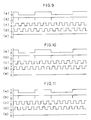
- Time charts of the signals 1 to V in the phase determination section 42 are illustrated in Fig. 9 to Fig. 11.
- (a) to (e) represent the variations of the binary reproduced signal 1, the edge signal II, the clock signal III, the delay signal IV and the phase determination signal V respectively.
- Fig. 9 illustrates a case where the PLL 35 is in a locked condition and the binary reproduced signal 1 and the clock signal III are in phase.
- the delay signal IV is always in the high level when the edge signal II falls whereby the phase determination signal V released by the flip-flop 38 is always in the high level.
- the frequency determination section 40 it is determined that the frequency of the clock signal III is comprised within a proper range and the frequency determination signal VI is in the high level, the CLV control switch is not performed.
- the time chart of Fig. 11 illustrates a case where the phase of the clock signal III of the phase locked loop 35 is leading.
- the clock signal III as shown by (c) in Fig. 11, is ahead of the binary reproduced signal 1 by approximately two-fifth of a cycle.
- the delay signal IV is always in the low level when the edge signal II falls, whereby the phase determination signal V is always in the low level also.
- the CLV control switch signal released by the AND circuit 41 is in the low level and the switch of the CLV control is executed.
- the present fourth embodiment is effective when a D.C. free modulation method is adopted.
- the D.C. free modulation method is a modulation method where the signal format used is such that there is no difference between the average level and the zero level of the binary reproduced signals, i.e. when the energy densities of "1" and "0" are both approximately equal to 50%. Whether the reproduced signals are in an appropriate condition is determined in the reproduced signal state detecting circuit 21. If the condition of the reproduced signals is poor, the CLV control is changed to the CLV control executed according to the reproduced signals of the pre-recorded information.
- binary reproduced signals released from the reproduced signal processing circuit 16 are fed into one of the input terminals of a NAND circuit 43 and are fed into one of the input terminals of a NAND circuit 45 through an inverter 44.
- Pulses sent from an oscillator 46 is entered in the other input terminal of the NAND circuit 43 and the other input terminal of the NAND circuit 45.
- Output signals released by the NAND circuit 43 are fed into an addition input terminal of an updown (U/D) counter 47 while output signals released by the HAND circuit 45 are fed into the subtraction input terminal of the updown counter 47.
- the updown counter 47 counts down.
- the value released by the updown counter 47 is compared with a reference value supplied from a reference value supply circuit 50 in a comparator 48.
- the comparator 48 When the value obtained in the updown counter 47 is greater than the reference value, it is assumed that anomalies arose in the energy densities of "1" and "0" of the binary reproduced signals and that the condition of the reproduced signals deteriorated.
- the comparator 48 consequently releases a CLV control switch signal.
- the optical disk recording/reproducing device of the present fifth embodiment is designed such that, when during the reproduction the optical head 4 entered into an unrecorded area of the information recording area 1b, the CLV control is switched to the CLV control executed according to the reproduced signals of the pre-recorded information.
- the reproduced signal state detecting circuit 21 comprises an envelope detecting circuit 51 and a comparator 52.
- An analog reproduced signal before it is converted into a binary reproduced signal, is released from the reproduced signal processing circuit 16 shown in Fig. 4 and fed into the envelope detecting circuit 51.
- the envelope detection of the analog reproduced signal is performed in the envelope detecting circuit 51.
- the voltage of the output signal obtained after the detection is compared with a reference voltage Vc in a comparator 52.
- the voltage of the envelope detection signal is below the reference voltage Vc.
- the CLV control switch signal released by the comparator 52 changes to the low level causing the CLV control to be switched to the CLV control based on the reproduced signals of the pre-recorded information during the reproduction also.
- the optical disk recording/reproducing device is designed such that, when during the reproduction the optical head 4 is positioned over an unrecorded area, the CLV control is switched to the CLV control executed according to the reproduced signals of the pre-recorded information.
- the reproduced signal state detecting circuit 21 comprises an edge detecting circuit 53 and a re-triggerable monostable multivibrator 54.
- Two-value reproduced signals released from the reproduced signal processing circuit 16 are fed into the edge detecting circuit 53.
- the time constant of the re-triggerable monostable multivibrator 54 is set so as to be, for example, slightly longer than the maximum length separating two edges of a binary reproduced signal shown by (b) in Fig. 9.
- the maximum distance separating two edges of a binary reproduced signal corresponds, for example, to 11 bits in an EFM signal.
- the re-triggerable monostable multivibrator 54 is triggered in a repetitive manner and thereby releases a signal that is constantly in the high level. In this case, the CLV control is not changed.
- the re-triggerable monostable multivibrator 54 is not triggered and releases a low level CLV control switch signal, causing the CLV control to be switched to the CLV control executed according to the pre-recorded information during the reproduction also.
- a seventh embodiment of the present invention will be described hereinbelow with reference to Fig. 15 and Fig. 16.
- the members having the same functions than in the previous embodiments will be designated by the same code and their description will be omitted.
- the optical disk recording/reproducing device of the present embodiment differs from the optical disk recording/reproducing devices of the previous embodiments in that it is not equipped with the reproduced signal state detecting circuit 21.
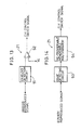
- Fig. 16 shows an address decoder 55, a TOC memory 56 and a controller 57 that are always part of the optical disk recording/reproducing device.
- the address decoder 55 decodes the sequences of data of the absolute addresses that went through the Biphasemark demodulation process described earlier.
- the absolute addresses are recognized in the controller 57 based on the results obtained in the address decoder 55.
- the address decoder 55 and a TOC memory 56 constitute an address management section.
- tile absolute addresses indicating recording start positions and the absolute addresses indicating recording end positions mentioned earlier are read from the TOC memory 56 by means of a recording/reproduction control section (not shown) comprised in the controller 57.
- the coil driver 10 drives the coil 5 and the optical head 4 to access the TOC area 1a in response to the instruction of the recording/reproduction control section.
- This instruction is based on the absolute addresses supplied by the pre-recorded information detecting circuit 12 and the address decoder 55.
- the recording start/end absolute addresses are recorded in the TOC area 1a after going through a prescribed signal process in the recording signal processing circuit 8.
- the recording start/end absolute addresses recorded in the TOC area 1a are stored in the TOC memory 56 of the address management section following the instruction of the recording/reproduction control section. Besides, absolute addresses processed and detected one after another in the pre-recorded information detecting circuit 12, are also fed into the TOC memory 56. The recording start/end absolute addresses and the absolute addresses detected one after another are compared in a comparison section (not shown) included in the controller 57. According to the result of the comparison, the comparison section determines whether the optical head 4 is reproducing a recorded area or an unrecorded area of the information recording area 1b.
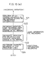
- a recording control operation that follows the flow illustrated in Fig. 15(a) and that is performed by control means composed of the controller 57 and other members will be described hereinbelow.
- a switch control section of the controller 57 switches the switching device 15 toward the first comparator 14. Consequently, the CLV control of the spindle motor 3 is executed based on the reproduced signals of the pre-recorded information (S21).
- the corresponding recording start absolute address is stored in the TOC memory 56 (S22).
- the corresponding recording end absolute address is also stored in the TOC memory 56 (S23). Then, the recording start/end absolute addresses are recorded as additional information in the TOC area 1a of the magneto-optical disk 1 as described earlier (S24).
- the control means switches the switching device 15 toward the comparator 20 permitting the CLV control of the spindle motor 3 to be performed according to the reproduced signals of the recorded information.
- a reproduction control operation performed by the control means that follows the flow illustrated in Fig. 15(b) will be described hereinbelow.
- the absolute addresses obtained one after another as the pre-recorded information preliminary recorded on the magneto-optical disk 1 is reproduced are compared with the recording start/end absolute addresses stored in the TOC memory 56 (S32). Then, it is determined whether the optical head 4 is located over a recorded area or an unrecorded area (S33). For instance, if the absolute addresses reproduced one after another, are greater than the recording start absolute address and smaller than the recording end absolute address, it is assumed that the optical head 4 is located over a recorded area. Accordingly, the switching device 15 stays connected to the second comparator 20 and the CLV control is performed based on the reproduced signals of the recorded information (S34).
- the optical head 4 is positioned over an unrecorded area.
- the switching device 15 is consequently switched from the second comparator 20 to the first comparator 14.
- the CLV control changes from the CLV control executed according to the reproduced signals of the recorded information to the CLV control executed according to the reproduced signals of the pre-recorded information (S35).
- the absolute addresses recorded on the magneto-optical disk 1 went through a Biphasemark modulation process.
- the magneto-optical disk was taken as an example of optical disk.
- the present invention may be applied to other Rewritable optical disks such as optical disks of the phase change type, or to Write-Once type optical disks.
- the absolute addresses serving as pre-recorded information were recorded on the optical disk by having the guiding groove 2 deviate.
- the absolute addresses may also be recorded on the optical disk in the form of aligned pits.
- the CLV control based on the reproduced signals of the pre-recorded information is carried out by comparing the cycle at which the pits are reproduced, with a predetermined reference frequency.
- the above embodiments described a case where the pre-recorded information is recorded on the optical disk in the form of absolute addresses.
- the pre-recorded information may also be recorded by having the guiding groove 2 snake.
- the unrecorded areas represented areas of the information recording area 1b that were not recorded.
- the present invention may be applied to for example unnecessary areas such as blank spaces or unstable recorded areas of recorded areas.
- an optical disk recording/reproducing device in accordance with the present invention comprises control means for executing the rotation control of an optical disk in Constant Linear Velocity such that: during the recording, the rotation control is carried out based on the reproduced signals of pre-recorded information that was preliminary recorded on the optical disk, during the reproduction, the rotation control is carried out based on the reproduced signals of recorded information, and when the rotation control based on the reproduced signals of the recorded information is infeasible, the control is switched to the rotation control based on the reproduced signals of the pre-recorded information during the reproduction also.
- the rotation control in Constant Linear Velocity is carried out according to the reproduced signals of the pre-recorded information during the recording, and based on the reproduced signals of the recorded information during the reproduction.
- This arrangement enables an appropriate and suitable rotation control to be performed during the recording and during the reproduction.
- an alternative method can be adopted.
- the alternative method consists in switching and executing the rotation control according to the reproduced signals of the pre-recorded information. Difficulties such as the infeasibility of the CLV control during reproduction, may be thus eliminated.
Landscapes
- Engineering & Computer Science (AREA)
- Multimedia (AREA)
- Signal Processing (AREA)
- Optical Recording Or Reproduction (AREA)
- Signal Processing For Digital Recording And Reproducing (AREA)
- Rotational Drive Of Disk (AREA)
Applications Claiming Priority (4)
| Application Number | Priority Date | Filing Date | Title |
|---|---|---|---|
| JP1203232A JPH0719432B2 (ja) | 1989-08-04 | 1989-08-04 | 光ディスク記録再生装置 |
| JP203231/89 | 1989-08-04 | ||
| JP1203231A JPH0719431B2 (ja) | 1989-08-04 | 1989-08-04 | 光ディスク記録再生装置 |
| JP203232/89 | 1989-08-04 |
Publications (3)
| Publication Number | Publication Date |
|---|---|
| EP0411961A2 true EP0411961A2 (fr) | 1991-02-06 |
| EP0411961A3 EP0411961A3 (en) | 1993-03-03 |
| EP0411961B1 EP0411961B1 (fr) | 1996-12-27 |
Family
ID=26513811
Family Applications (1)
| Application Number | Title | Priority Date | Filing Date |
|---|---|---|---|
| EP90308577A Expired - Lifetime EP0411961B1 (fr) | 1989-08-04 | 1990-08-03 | Appareil d'enregistrement/de reproduction de disque optique |
Country Status (5)
| Country | Link |
|---|---|
| US (1) | US5093820A (fr) |
| EP (1) | EP0411961B1 (fr) |
| KR (1) | KR940001998B1 (fr) |
| CA (1) | CA2022192C (fr) |
| DE (1) | DE69029491T2 (fr) |
Cited By (2)
| Publication number | Priority date | Publication date | Assignee | Title |
|---|---|---|---|---|
| US5805551A (en) * | 1994-04-18 | 1998-09-08 | Matsushita Electric Industrial Co., Ltd. | Method and apparatus for preventing illegal copy or illegal installation of information of optical recording medium |
| US5881038A (en) * | 1994-04-18 | 1999-03-09 | Matsushita Electric Industrial Co., Ltd. | Method and apparatus for preventing illegal copy or illegal installation of information of optical recording medium |
Families Citing this family (19)
| Publication number | Priority date | Publication date | Assignee | Title |
|---|---|---|---|---|
| CA2054880C (fr) * | 1990-11-09 | 1997-07-08 | Shigemi Maeda | Dispositif d'enregistrement et de lecture d'informations |
| JP2762765B2 (ja) * | 1991-04-18 | 1998-06-04 | 松下電器産業株式会社 | 記録再生方法及び記録再生装置及び記録方法及び記録装置 |
| JPH05101527A (ja) * | 1991-10-07 | 1993-04-23 | Chuo Denki Kk | デイスク再生装置 |
| US5528574A (en) * | 1992-03-09 | 1996-06-18 | Hitachi, Ltd. | Disk reproducing apparatus capable of increasing speed of access to disks recorded at constant linear velocity |
| US5583838A (en) * | 1992-03-12 | 1996-12-10 | Mitsubishi Denki Kabushiki Kaisha | Recording apparatus having data recording rate phase-synchronized to recording time data recorded on a recording medium |
| JP3218743B2 (ja) * | 1992-10-16 | 2001-10-15 | ソニー株式会社 | 記録/再生装置、ディスク記録再生システム、及び記録方法 |
| JP3352132B2 (ja) * | 1992-12-11 | 2002-12-03 | キヤノン株式会社 | 光学的情報再生装置 |
| WO1994019800A1 (fr) * | 1993-02-22 | 1994-09-01 | Sony Corporation | Appareil a disque optique |
| US5388085A (en) * | 1993-03-03 | 1995-02-07 | International Business Machines Corporation | Apparatus and method for accessing sectors of a rotating disk |
| JPH0773471A (ja) * | 1993-09-03 | 1995-03-17 | Pioneer Electron Corp | 追記型光ディスクの情報記録装置 |
| US5486745A (en) * | 1993-10-05 | 1996-01-23 | Miles Inc. | Method and apparatus for synchronizing system operations using a programmable element |
| BE1007852A3 (nl) * | 1993-12-03 | 1995-11-07 | Philips Electronics Nv | Compatibele optische uitleesinrichting. |
| JPH087467A (ja) * | 1994-06-14 | 1996-01-12 | Teac Corp | 光ディスク装置 |
| US5691967A (en) * | 1994-09-20 | 1997-11-25 | Sony Corporation | Recording or reproducing apparatus having a spindle servo control runaway prevent feature |
| KR100329151B1 (ko) * | 1995-04-27 | 2002-11-29 | 삼성전자 주식회사 | 디스크구동기록장치의스핀들모터구동제어회로 |
| JP3889457B2 (ja) * | 1996-03-13 | 2007-03-07 | パイオニア株式会社 | 回転制御装置及び回転制御方法 |
| KR100528108B1 (ko) * | 1996-11-22 | 2006-03-16 | 산요덴키가부시키가이샤 | 고정밀동기화를실현할수있는동기회로및광디스크재생장치 |
| US6233633B1 (en) * | 1998-03-05 | 2001-05-15 | Sony Corporation | Data transfer between a computer and a digital storage device using a computer sound card to convert the processed digital data to analog form |
| JP4234921B2 (ja) * | 2001-09-12 | 2009-03-04 | 株式会社リコー | 情報記録装置 |
Citations (7)
| Publication number | Priority date | Publication date | Assignee | Title |
|---|---|---|---|---|
| EP0049136A2 (fr) * | 1980-09-30 | 1982-04-07 | Kabushiki Kaisha Toshiba | Dispositif de contrôle de la vitesse de rotation d'un disque d'enregistrement |
| DE3334900A1 (de) * | 1982-09-27 | 1984-03-29 | Tokyo Shibaura Denki K.K., Kawasaki, Kanagawa | Mit drehbarer speicherplatte arbeitende vorrichtung |
| EP0178657A2 (fr) * | 1984-10-17 | 1986-04-23 | Sony Corporation | Appareil pour enregistrer et/ou reproduire un signal de données sur un moyen d'enregistrement en forme de disque ou à partir de celui-ci |
| EP0228848A2 (fr) * | 1985-12-20 | 1987-07-15 | Sony Corporation | Appareil de reproduction de disques |
| WO1988004824A2 (fr) * | 1986-12-19 | 1988-06-30 | Eastman Kodak Company | Distribution d'indices d'horloge pour un disque a vitesse lineaire quasi-constante |
| EP0302680A2 (fr) * | 1987-07-31 | 1989-02-08 | Sharp Kabushiki Kaisha | Appareil d'enregistrement et de reproduction sur disque optique |
| JPH1013282A (ja) * | 1996-03-14 | 1998-01-16 | Philips Electron Nv | 無線受信器の電力節約の方法 |
Family Cites Families (4)
| Publication number | Priority date | Publication date | Assignee | Title |
|---|---|---|---|---|
| JPH0746463B2 (ja) * | 1985-11-15 | 1995-05-17 | ティアツク株式会社 | 等線速度方式情報記録円盤の回転制御装置 |
| JPH0734288B2 (ja) * | 1986-09-24 | 1995-04-12 | 株式会社日立製作所 | デイスク回転駆動装置 |
| JPH0652571B2 (ja) * | 1987-06-23 | 1994-07-06 | ティアツク株式会社 | 光ディスク再生装置 |
| NL8701632A (nl) * | 1987-07-10 | 1989-02-01 | Philips Nv | Systeem voor het optekenen en/of uitlezen van een informatiesignaal, een registratiedrager, een opteken en/of uitleesinrichting voor toepassing in een dergelijk systeem, en een inrichting en werkwijze voor het vervaardigen van een dergelijke registratiedrager. |
-
1990
- 1990-07-27 CA CA002022192A patent/CA2022192C/fr not_active Expired - Lifetime
- 1990-08-02 US US07/561,822 patent/US5093820A/en not_active Expired - Lifetime
- 1990-08-02 KR KR1019900011856A patent/KR940001998B1/ko not_active IP Right Cessation
- 1990-08-03 EP EP90308577A patent/EP0411961B1/fr not_active Expired - Lifetime
- 1990-08-03 DE DE69029491T patent/DE69029491T2/de not_active Expired - Fee Related
Patent Citations (7)
| Publication number | Priority date | Publication date | Assignee | Title |
|---|---|---|---|---|
| EP0049136A2 (fr) * | 1980-09-30 | 1982-04-07 | Kabushiki Kaisha Toshiba | Dispositif de contrôle de la vitesse de rotation d'un disque d'enregistrement |
| DE3334900A1 (de) * | 1982-09-27 | 1984-03-29 | Tokyo Shibaura Denki K.K., Kawasaki, Kanagawa | Mit drehbarer speicherplatte arbeitende vorrichtung |
| EP0178657A2 (fr) * | 1984-10-17 | 1986-04-23 | Sony Corporation | Appareil pour enregistrer et/ou reproduire un signal de données sur un moyen d'enregistrement en forme de disque ou à partir de celui-ci |
| EP0228848A2 (fr) * | 1985-12-20 | 1987-07-15 | Sony Corporation | Appareil de reproduction de disques |
| WO1988004824A2 (fr) * | 1986-12-19 | 1988-06-30 | Eastman Kodak Company | Distribution d'indices d'horloge pour un disque a vitesse lineaire quasi-constante |
| EP0302680A2 (fr) * | 1987-07-31 | 1989-02-08 | Sharp Kabushiki Kaisha | Appareil d'enregistrement et de reproduction sur disque optique |
| JPH1013282A (ja) * | 1996-03-14 | 1998-01-16 | Philips Electron Nv | 無線受信器の電力節約の方法 |
Non-Patent Citations (1)
| Title |
|---|
| PATENT ABSTRACTS OF JAPAN vol. 13, no. 185 (P-865)2 May 1989 & JP-A-10 13 282 ( PIONEER ELECTRONIC CORPORATION ) 18 January 1989 * |
Cited By (2)
| Publication number | Priority date | Publication date | Assignee | Title |
|---|---|---|---|---|
| US5805551A (en) * | 1994-04-18 | 1998-09-08 | Matsushita Electric Industrial Co., Ltd. | Method and apparatus for preventing illegal copy or illegal installation of information of optical recording medium |
| US5881038A (en) * | 1994-04-18 | 1999-03-09 | Matsushita Electric Industrial Co., Ltd. | Method and apparatus for preventing illegal copy or illegal installation of information of optical recording medium |
Also Published As
| Publication number | Publication date |
|---|---|
| US5093820A (en) | 1992-03-03 |
| CA2022192C (fr) | 1995-03-21 |
| KR940001998B1 (ko) | 1994-03-12 |
| CA2022192A1 (fr) | 1991-02-05 |
| DE69029491D1 (de) | 1997-02-06 |
| EP0411961A3 (en) | 1993-03-03 |
| DE69029491T2 (de) | 1997-05-28 |
| EP0411961B1 (fr) | 1996-12-27 |
| KR910005244A (ko) | 1991-03-30 |
Similar Documents
| Publication | Publication Date | Title |
|---|---|---|
| CA2022192C (fr) | Dispositif d'enregistrement-lecture a disque optique | |
| EP0414557B1 (fr) | Appareil d'enregistrement/reproduction pour disque optique | |
| US5754522A (en) | Method for forming disk, disk forming apparatus, data recording/reproducing method, data recording/reproducing apparatus, and disk capable of recording/reproducing data in high density | |
| EP0974966B1 (fr) | Système d'enregistrement de disque | |
| EP1066628B1 (fr) | Support d'enregistrement et appareil pour balayer ledit support d'enregistrement | |
| CA2054880C (fr) | Dispositif d'enregistrement et de lecture d'informations | |
| JP2583645B2 (ja) | 情報記録再生装置 | |
| EP0872838B1 (fr) | Appareil de commande de rotation de disque | |
| EP0064196A1 (fr) | Appareil d'enregistrement et de reproduction de données optiques | |
| US6181655B1 (en) | Optical disc drive, timing signal generator, and information recording and reproduction method | |
| EP0593233A2 (fr) | Appareil de reproduction d'information | |
| KR100502461B1 (ko) | 위상동기루프회로및이것이내장된재생장치 | |
| JPH0927127A (ja) | 光ディスク、光ディスク装置および光ディスク記録再生方法 | |
| JPH0719431B2 (ja) | 光ディスク記録再生装置 | |
| EP0409649B1 (fr) | Dispositif d'enregistrement et de reproduction | |
| JP3875399B2 (ja) | 光ディスク装置のトラッキング方法とdvd−ramドライブ装置のトラッキング方法 | |
| JP3478585B2 (ja) | 光ディスク再生装置及びその制御方法 | |
| JP2585467B2 (ja) | 再生データ処理装置 | |
| JPH07141781A (ja) | データ再生用pll回路の制御装置 | |
| JPH10222923A (ja) | Cd−rom装置 | |
| JPH0581771A (ja) | 光デイスク装置 |
Legal Events
| Date | Code | Title | Description |
|---|---|---|---|
| PUAI | Public reference made under article 153(3) epc to a published international application that has entered the european phase |
Free format text: ORIGINAL CODE: 0009012 |
|
| 17P | Request for examination filed |
Effective date: 19900830 |
|
| AK | Designated contracting states |
Kind code of ref document: A2 Designated state(s): DE FR GB IT NL |
|
| PUAL | Search report despatched |
Free format text: ORIGINAL CODE: 0009013 |
|
| AK | Designated contracting states |
Kind code of ref document: A3 Designated state(s): DE FR GB IT NL |
|
| 17Q | First examination report despatched |
Effective date: 19940504 |
|
| GRAG | Despatch of communication of intention to grant |
Free format text: ORIGINAL CODE: EPIDOS AGRA |
|
| GRAH | Despatch of communication of intention to grant a patent |
Free format text: ORIGINAL CODE: EPIDOS IGRA |
|
| GRAH | Despatch of communication of intention to grant a patent |
Free format text: ORIGINAL CODE: EPIDOS IGRA |
|
| GRAA | (expected) grant |
Free format text: ORIGINAL CODE: 0009210 |
|
| AK | Designated contracting states |
Kind code of ref document: B1 Designated state(s): DE FR GB IT NL |
|
| PG25 | Lapsed in a contracting state [announced via postgrant information from national office to epo] |
Ref country code: IT Free format text: LAPSE BECAUSE OF FAILURE TO SUBMIT A TRANSLATION OF THE DESCRIPTION OR TO PAY THE FEE WITHIN THE PRE;WARNING: LAPSES OF ITALIAN PATENTS WITH EFFECTIVE DATE BEFORE 2007 MAY HAVE OCCURRED AT ANY TIME BEFORE 2007. THE CORRECT EFFECTIVE DATE MAY BE DIFFERENT FROM THE ONE RECORDED.SCRIBED TIME-LIMIT Effective date: 19961227 |
|
| REF | Corresponds to: |
Ref document number: 69029491 Country of ref document: DE Date of ref document: 19970206 |
|
| ET | Fr: translation filed | ||
| PLBE | No opposition filed within time limit |
Free format text: ORIGINAL CODE: 0009261 |
|
| STAA | Information on the status of an ep patent application or granted ep patent |
Free format text: STATUS: NO OPPOSITION FILED WITHIN TIME LIMIT |
|
| 26N | No opposition filed | ||
| REG | Reference to a national code |
Ref country code: GB Ref legal event code: IF02 |
|
| PGFP | Annual fee paid to national office [announced via postgrant information from national office to epo] |
Ref country code: DE Payment date: 20080814 Year of fee payment: 19 Ref country code: NL Payment date: 20080815 Year of fee payment: 19 |
|
| PGFP | Annual fee paid to national office [announced via postgrant information from national office to epo] |
Ref country code: FR Payment date: 20080818 Year of fee payment: 19 |
|
| PGFP | Annual fee paid to national office [announced via postgrant information from national office to epo] |
Ref country code: GB Payment date: 20080813 Year of fee payment: 19 |
|
| REG | Reference to a national code |
Ref country code: NL Ref legal event code: V1 Effective date: 20100301 |
|
| GBPC | Gb: european patent ceased through non-payment of renewal fee |
Effective date: 20090803 |
|
| REG | Reference to a national code |
Ref country code: FR Ref legal event code: ST Effective date: 20100430 |
|
| PG25 | Lapsed in a contracting state [announced via postgrant information from national office to epo] |
Ref country code: FR Free format text: LAPSE BECAUSE OF NON-PAYMENT OF DUE FEES Effective date: 20090831 Ref country code: DE Free format text: LAPSE BECAUSE OF NON-PAYMENT OF DUE FEES Effective date: 20100302 Ref country code: NL Free format text: LAPSE BECAUSE OF NON-PAYMENT OF DUE FEES Effective date: 20100301 |
|
| PG25 | Lapsed in a contracting state [announced via postgrant information from national office to epo] |
Ref country code: GB Free format text: LAPSE BECAUSE OF NON-PAYMENT OF DUE FEES Effective date: 20090803 |