EP0409944B1 - Windscreen wiper system - Google Patents
Windscreen wiper system Download PDFInfo
- Publication number
- EP0409944B1 EP0409944B1 EP90902209A EP90902209A EP0409944B1 EP 0409944 B1 EP0409944 B1 EP 0409944B1 EP 90902209 A EP90902209 A EP 90902209A EP 90902209 A EP90902209 A EP 90902209A EP 0409944 B1 EP0409944 B1 EP 0409944B1
- Authority
- EP
- European Patent Office
- Prior art keywords
- wiper system
- carrier
- motor
- pipe
- stud
- Prior art date
- Legal status (The legal status is an assumption and is not a legal conclusion. Google has not performed a legal analysis and makes no representation as to the accuracy of the status listed.)
- Expired - Lifetime
Links
Images


Classifications
-
- B—PERFORMING OPERATIONS; TRANSPORTING
- B60—VEHICLES IN GENERAL
- B60S—SERVICING, CLEANING, REPAIRING, SUPPORTING, LIFTING, OR MANOEUVRING OF VEHICLES, NOT OTHERWISE PROVIDED FOR
- B60S1/00—Cleaning of vehicles
- B60S1/02—Cleaning windscreens, windows or optical devices
- B60S1/04—Wipers or the like, e.g. scrapers
- B60S1/0413—Modular wiper assembly
- B60S1/0422—Modular wiper assembly having a separate transverse element
- B60S1/0427—Modular wiper assembly having a separate transverse element characterised by the attachment of the wiper motor holder to the transverse element
-
- B—PERFORMING OPERATIONS; TRANSPORTING
- B60—VEHICLES IN GENERAL
- B60S—SERVICING, CLEANING, REPAIRING, SUPPORTING, LIFTING, OR MANOEUVRING OF VEHICLES, NOT OTHERWISE PROVIDED FOR
- B60S1/00—Cleaning of vehicles
- B60S1/02—Cleaning windscreens, windows or optical devices
- B60S1/04—Wipers or the like, e.g. scrapers
- B60S1/0413—Modular wiper assembly
- B60S1/0422—Modular wiper assembly having a separate transverse element
- B60S1/0425—Modular wiper assembly having a separate transverse element characterised by the attachment of the wiper shaft holders to the transverse element
-
- Y—GENERAL TAGGING OF NEW TECHNOLOGICAL DEVELOPMENTS; GENERAL TAGGING OF CROSS-SECTIONAL TECHNOLOGIES SPANNING OVER SEVERAL SECTIONS OF THE IPC; TECHNICAL SUBJECTS COVERED BY FORMER USPC CROSS-REFERENCE ART COLLECTIONS [XRACs] AND DIGESTS
- Y10—TECHNICAL SUBJECTS COVERED BY FORMER USPC
- Y10T—TECHNICAL SUBJECTS COVERED BY FORMER US CLASSIFICATION
- Y10T74/00—Machine element or mechanism
- Y10T74/18—Mechanical movements
- Y10T74/18056—Rotary to or from reciprocating or oscillating
- Y10T74/18184—Crank, pitman, and lever
-
- Y—GENERAL TAGGING OF NEW TECHNOLOGICAL DEVELOPMENTS; GENERAL TAGGING OF CROSS-SECTIONAL TECHNOLOGIES SPANNING OVER SEVERAL SECTIONS OF THE IPC; TECHNICAL SUBJECTS COVERED BY FORMER USPC CROSS-REFERENCE ART COLLECTIONS [XRACs] AND DIGESTS
- Y10—TECHNICAL SUBJECTS COVERED BY FORMER USPC
- Y10T—TECHNICAL SUBJECTS COVERED BY FORMER US CLASSIFICATION
- Y10T74/00—Machine element or mechanism
- Y10T74/21—Elements
- Y10T74/2186—Gear casings
Definitions
- the invention relates to a wiper system according to the features of the preamble of claim 1.
- a wiper system is known with a support designed as a square tube, at the end of which a wiper bearing is fixed.
- a plate serving as a motor support part is welded to this square tube, to which the drive motor of the wiper system is attached.
- These wiper systems often referred to as tubular frame systems, have become popular in recent years because of their light construction and great stability.
- tubular frame systems can have disadvantages compared to the other known systems with a cast aluminum frame if there are restricted installation conditions in a motor vehicle and therefore this tube connecting the wiper bearings would have to be angled several times into different planes. Then the bending effort for this tube becomes very large and the stability of the frame suffers.
- GB-A-677147 also discloses a wiper system in which the motor mount is connected in a dimensionally stable manner with the aid of bolt connections by means of corresponding approaches to two supports.
- this type of connection has the result that both the lugs and the carriers in the common connection area are exposed to large leverage forces and, on the other hand, they experience a material weakening which results from bores for the bolts.
- the invention is therefore based on the object of developing a wiper system of the type mentioned at the outset with a tubular support to form a wiper bearing in such a way that sufficient stability is achieved with simple means even in difficult installation conditions.
- the invention is therefore based on the consideration that one can better cope with cramped spatial conditions if the tubular support is fixed to the motor support part in the axial direction, so to speak, that is to put it on a shoulder.
- a conventional wiper system with two Wiper bearings means that the tube-like carrier, which was previously common, is separated into two sections, each of which is attached to a shoulder on the motor carrier. While in the previously known systems, the two wiper bearings are fixed at the ends of a single tube and the motor support part is fixed tangentially to this tube, in the embodiment according to the invention, each tubular support is fastened on one side to the motor support part, so that the entire support frame consists of two pipe sections and the engine support part itself.
- the present invention is not limited to wiper systems in which two wiper bearings are fixed to tubular supports.
- the basic idea can also be realized with advantage if, for example for rear windshield wiper systems on motor vehicles, there is only one wiper bearing which is inserted axially into one pipe end, this pipe end then in turn being axially plugged onto a shoulder on a motor support part and fixed there in a dimensionally stable manner is.
- designs are also conceivable in which only one wiper bearing is fixed to a tube, while the second wiper bearing is attached to the motor vehicle in another way.
- the stability of such a wiper system can be significantly improved by designing the lugs on the motor support part so that straight tubular supports can be used.
- This is relatively simple, in particular, if the motor support part is made as a die-cast part from aluminum or zinc according to a particularly preferred development of the invention.
- Such a die-cast part can in fact be shaped at such a high cost that assembly of the wiper system is possible even in tight installation conditions.
- This engine support part which is produced as a die-cast part, can also be designed such that the wiper bearings and the drive axis of the drive motor are as straight as possible. This has the advantage that no phase shift can be observed during the wiping process of the two wipers.
- a fastening element for example a fastening eye, can also be provided without difficulty, via which this engine support part can be attached to the body of the motor vehicle.
- this motor support part is now formed in one piece with a part belonging to the drive motor.
- This motor support part can be formed in one piece with the gear housing, which is made of die-cast zinc in most wiper motors anyway.
- the motor support part can also be part of the gearbox cover.
- the gear housing is composed of two preferably identical halves, in which case both gear housing halves have lugs to which the tubular supports can be fixed. This considerably increases the possible uses of such an engine with an integrated engine support part.
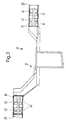
- FIGS. 1 to 14 Of the windshield wiper system, only the elements essential to the present invention are shown in FIGS. 1 to 14. With 10 and 11 two wiper bearings are designated, in which the wiper shafts 12 and 13 are rotatably mounted in a known manner via bearing bushes. These wiper bearings are made of die-cast zinc and each have an attachment 14, 15 in one piece, the spatial shape of which will be described later in connection with FIGS. 5 to 7.
- the wiper system includes tubular supports 20, 21 with a preferably circular cross section. An extension 14, 15 of a wiper bearing 10, 11 is inserted into one end E1 of these tubular supports 20, 21. In the other end E2 of these tubular supports 20, 21 are projections 30, 31 of a motor support part designated overall by 32.
- the support frame of this wiper system thus consists of two tubular supports 20, 21 and the motor support part 32, which is made as a die-cast part made of aluminum or zinc.
- the tubular supports 20, 21 are fixed in shape to the projections on the wiper bearing or the motor support part, which will be described later. It can be seen from FIGS. 1 and 2 that these tubular supports 20, 21 lie in different planes, the offset required for this being able to be implemented without difficulty by the correspondingly shaped motor support part 32.
- Fig. 2 are designated 33 mounting holes to which the actual drive motor of the wiper system is fixed by screwing.
- the output axis of the drive motor then extends along the line A.
- a straight line G is indicated, which connects the two wiper bearings 10, 11 to one another. It can be seen that the distance between this output axis A of this motor and this straight line G, which connects the wiper bearings 10, 11 to one another, is relatively small, so that there is no significant phase shift between the wiping movements of the two wipers.
- This is achieved by the arrangement of the lugs 30, 31, which can be seen in FIG. 2. It is important in this connection that the lugs 30, 31 are aligned in such a way that straight tubular supports 20, 21 are used can. This has the advantage that no expensive bending processes are required and that the stability of the connection also meets all requirements in the case of straight tubular supports.
- a fastening eye 34 is formed on the engine support part 32 produced as a die-cast part, which can generally be regarded as a fastening element and enables this engine support part 32 to be attached to the body of the motor vehicle, which is not shown in detail.
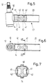
- each approach has two recesses 41 on both sides of a central web 40. Pipe sections 42 of the tubular support 20 are pressed into these recesses 41, which can be clearly seen in particular from FIG. 7.
- the tubular support 20, 21 is thus deformed in such a way that it adapts in sections to the non-circular contour of the projections 14, 15 and 30, 31, respectively. In this way, a positive connection between the approaches and the tubular supports is achieved.
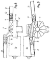
- FIGS. 8 to 11 show the drive motor 50, to which a gear housing 51 belongs, which is closed off by a cover 52. It is essential in the embodiment according to FIGS. 8 and 9 that the lugs 30, 31 are integrally formed on this gear housing 51, which can be made in a known manner from die-cast zinc, on which the ends E2 of the tubular carrier 20, 21 can be attached.
- the motor support part is, as it were, connected in one piece to a part of the drive motor 50, namely the gear housing 51.
- the fact could also be expressed in such a way that in this embodiment the motor support part - at least as a separate part - is omitted and by one appropriately designed gear housing 51 of the drive motor 50 is replaced.
- FIGS. 10 and 11 differs from the embodiment according to FIGS. 8 and 9 in that these projections 30, 31 are now formed on the cover 52, which is then also designed as a die-cast part.
- This gear housing could also be composed of two preferably identical gear housing halves, in which case each gear housing half should have such approaches so that this drive motor can be used as universally as possible for different wiper systems.
- the mounting of the output shaft 53 of the drive motor 50 can also be improved because storage is now possible on both sides of the worm wheel usually connected to the output shaft.
- the support frame for a wiper system with two wiper bearings consists of two tubular supports and an intermediate piece connecting these tubular supports in the form of a motor support part.
- This motor support part is designed as a die-cast part and can thus be designed in a simple manner so that subsequent pipe sections do not have to be bent if possible. Due to the use of straight tubes, this support frame is very torsion-resistant.
- a die-cast part as an intermediate piece between the two straight tubular supports, it is possible to create cost-effective wiper systems which can be assembled without difficulty even in complicated installation situations.
- the two wiper shafts can be driven directly from an engine crank, whereby phase shifts between the two wiping movements can be largely avoided.
- the manufacturing costs of such a wiper system are comparatively low.
- the wiper bearings made of die-cast zinc do not require any reworking at the point of attachment with the tubular support.
- the tube-like supports first have to be cut to length.
- the engine support part is also used as a die-cast part sprayed directly into the ready-to-use form. All parts are connected to one another by simply plugging them together, in which case the positive connections are then preferably produced in a single operation by non-cutting deformation of the tubular supports.
- changes are comparatively easy to carry out, because in many situations only the length of the tubular support has to be changed.
- a tubular support with a round cross section is used because the position of the wiper bearing can then be varied by rotation.
- square tubes could also be used as supports.
- the basic idea of the invention can be implemented using a separate motor support part, but designs are preferred in which this motor support part is not required as a separate part and the approaches for the dimensionally stable fixing of the tubular supports are molded directly onto a component of the gear housing of the drive motor.
- the gear housing takes over one supporting function of the frame. Since this gear housing is made of die-cast zinc, a fastening element, for example a fastening eye, can be molded on without additional effort, so that no additional components are required to fix the entire wiper system to the body.
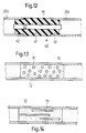
- 12 shows two parts 20a, 20b of a tubular support 20 which are connected to one another via an intermediate piece 60.
- This intermediate piece 60 is made of a noise-damping, frequency-filtering or noise-absorbing material, for example made of plastic. It consists of a spacer 61, from which projections 62, 63 extend on both sides, which are pressed into the tubular supports 20a, 20b. To stiffen the system, the spacer 61 and the side lugs 62, 63 can have a continuous bore 64 for the use of a reinforcing pin 65.
- the transmission of the tubular support 20 in two and the interposition of an intermediate piece 60, which serves as a noise-damping element significantly reduce noise transmission.
- FIGS. 13 and 14 the noise damping element 60 being here to a certain extent achieved by perforating the tubular support 20.
- 13 shows an embodiment in which this tubular support 20 has round openings 70 in a certain area.
- elongated openings 71 are provided.
- the tubular support 20 is filled with a noise-absorbing material 72, for example foamed.
- This measure allows resonance frequencies that arise to be largely filtered out and thus also attenuated, so that they are not transmitted to the body.
- care must be taken that the stability of the support frame is not inadmissibly reduced as a result.
Abstract
Description
Die Erfindung bezieht sich auf eine Wischeranlage gemäß den Merkmalen des Oberbegriffes des Anspruches 1.The invention relates to a wiper system according to the features of the preamble of claim 1.
Aus der gattungsbildenden DE-U-74 34 119 ist eine Wischeranlage mit einem als Vierkantrohr ausgebildeten Träger bekannt, an dessen Ende jeweils ein Wischerlager fixiert ist. An diesem Vierkantrohr ist eine als Motortragteil dienende Platte angeschweißt, an der der Antriebsmotor der Wischeranlage befestigt ist. Diese oft als Rohrrahmenanlage bezeichneten Wischeranlagen haben sich wegen ihrer leichten Bauweise bei großer Stabilität in den letzten Jahren durchgesetzt. Allerdings hat sich gezeigt, daß derartige Rohrrahmenanlagen gegenüber den anderen bekannten Systemen mit einem gegossenen Aluminiumrahmen dann Nachteile aufweisen können, wenn in einem Kraftfahrzeug beengte Einbauverhältnisse gegeben sind und daher dieses die Wischerlager verbindende Rohr mehrfach in unterschiedliche Ebenen abgewinkelt werden müßte. Dann wird der Biegeaufwand für dieses Rohr sehr groß und die Stabilität des Rahmens leidet darunter. Nachteilig bei dieser bekannten Anlage ist außerdem, daß durch den Schweißvorgang zwischen dem Motortragteil und dem rohrartigen Träger nicht unbeträchtliche Kosten anfallen, die sich natürlich im Preis der gesamten Wischeranlage niederschlagen. Ferner ist in der GB-A-677147 eine Wischeranlage offenbart, bei welcher der Motorträger über entsprechende Ansätze mit zwei Trägern formstabil mit Hilfe von Bolzenverbindungen verbunden ist. Diese Art von Verbindung hat jedoch zur Folge, daß sowohl die Ansätze als auch die Träger im gemeinsamen Verbindungsbereich zum einen großen Hebelkräften ausgesetzt sind und zum anderen eine Materialschwächung erfahren, die sich aufgrund von Bohrungen für die Bolzen ergibt.From the generic DE-U-74 34 119 a wiper system is known with a support designed as a square tube, at the end of which a wiper bearing is fixed. A plate serving as a motor support part is welded to this square tube, to which the drive motor of the wiper system is attached. These wiper systems, often referred to as tubular frame systems, have become popular in recent years because of their light construction and great stability. However, it has been shown that such tubular frame systems can have disadvantages compared to the other known systems with a cast aluminum frame if there are restricted installation conditions in a motor vehicle and therefore this tube connecting the wiper bearings would have to be angled several times into different planes. Then the bending effort for this tube becomes very large and the stability of the frame suffers. Another disadvantage of this known system is that the welding process between the motor support part and the tubular support incurs considerable costs, which of course are reflected in the price of the entire wiper system. GB-A-677147 also discloses a wiper system in which the motor mount is connected in a dimensionally stable manner with the aid of bolt connections by means of corresponding approaches to two supports. However, this type of connection has the result that both the lugs and the carriers in the common connection area are exposed to large leverage forces and, on the other hand, they experience a material weakening which results from bores for the bolts.
Der Erfindung liegt daher die Aufgabe zugrunde, eine Wischeranlage der eingangs erwähnten Art mit einem rohrartigen Träger zu einem Wischerlager derart weiterzubilden, daß mit einfachen Mitteln eine ausreichende Stabilität auch bei schwierigen Einbauverhältnissen erreicht wird.The invention is therefore based on the object of developing a wiper system of the type mentioned at the outset with a tubular support to form a wiper bearing in such a way that sufficient stability is achieved with simple means even in difficult installation conditions.
Die gestellte Aufgabe wird erfindungsgemäß durch die Merkmale des Anspruches 1 gelöst.The object is achieved according to the invention by the features of claim 1.
Die Erfindung basiert also auf der Überlegung, daß man beengten Raumverhältnissen besser gerecht werden kann, wenn man den rohrartigen Träger gewissermaßen in axialer Richtung am Motortragteil fixiert, also auf einen Ansatz aufsteckt. Bei einer herkömmlichen Wischeranlage mit zwei Wischerlagern bedeutet dieses also eine Trennung des bisher üblichen rohrartigen Trägers in zwei Teilstücke, die jeweils auf einen Ansatz am Motorträger aufgesteckt werden. Während bei den bisher bekannten Anlagen die beiden Wischerlager an den Enden eines einzigen Rohres fixiert werden und das Motortragteil gewissermaßen tangential an diesem Rohr fixiert wird, ist bei der erfindungsgemäßen Ausführung jeder rohrartige Träger einseitig am Motortragteil befestigt, so daß der gesamte Tragrahmen aus zwei Rohrstücken und dem Motortragteil selbst besteht.The invention is therefore based on the consideration that one can better cope with cramped spatial conditions if the tubular support is fixed to the motor support part in the axial direction, so to speak, that is to put it on a shoulder. In a conventional wiper system with two Wiper bearings means that the tube-like carrier, which was previously common, is separated into two sections, each of which is attached to a shoulder on the motor carrier. While in the previously known systems, the two wiper bearings are fixed at the ends of a single tube and the motor support part is fixed tangentially to this tube, in the embodiment according to the invention, each tubular support is fastened on one side to the motor support part, so that the entire support frame consists of two pipe sections and the engine support part itself.
Es wird bei dieser Gelegenheit bereits darauf hingewiesen, daß die vorliegende Erfindung aber nicht auf Wischeranlagen beschränkt ist, bei denen zwei Wischerlager an rohrartigen Trägern fixiert werden. Der Grundgedanke kann vielmehr auch mit Vorteil dann realisiert werden, wenn bespielsweise für Heckscheibenwischeranlagen an Kraftfahrzeugen - nur ein Wischerlager vorhanden ist, das axial in das eine Rohrende eingesteckt ist, wobei dann dieses Rohrende wiederum axial auf einen Ansatz an einem Motortragteil aufgesteckt und dort formstabil fixiert ist. Außerdem sind auch Ausführungen denkbar, bei denen nur ein Wischerlager an einem Rohr fixiert ist, während das zweite Wischerlager auf andere Weise am Kraftfahrzeug befestigt ist.It is already pointed out on this occasion that the present invention is not limited to wiper systems in which two wiper bearings are fixed to tubular supports. The basic idea can also be realized with advantage if, for example for rear windshield wiper systems on motor vehicles, there is only one wiper bearing which is inserted axially into one pipe end, this pipe end then in turn being axially plugged onto a shoulder on a motor support part and fixed there in a dimensionally stable manner is. In addition, designs are also conceivable in which only one wiper bearing is fixed to a tube, while the second wiper bearing is attached to the motor vehicle in another way.
Die Stabilität einer solchen Wischeranlage kann wesentlich dadurch verbessert werden, daß man die Ansätze am Motortragteil so ausbildet, daß man gerade rohrartige Träger verwenden kann. Dies ist insbesondere dann verhältnismäßig einfach, wenn das Motortragteil gemäß einer besonders bevorzugten Weiterbildung der Erfindung als Druckgußteil aus Aluminium oder Zink hergestellt ist. Ein solches Druckgußteil kann nämlich ohne größere Kosten so geformt werden, daß selbst bei beengten Einbauverhältnissen eine Montage der Wischeranlage möglich ist. Dabei kann dieses als Druckgußteil hergestellte Motortragteil auch noch so ausgebildet werden, daß die Wischerlager und die Antriebsachse des Antriebsmotors möglichst auf einer geraden Linie liegen. Dies hat den Vorteil, daß keine Phasenverschiebung beim Wischvorgang der beiden Wischer zu beobachten ist. Bei Verwendung eines Druckgußteils kann man außerdem ohne Schwierigkeiten ein Befestigungselement, beispielsweise ein Befestigungsauge, vorsehen, über das dieses Motortragteil an der Karosserie des Kraftfahrzeugs befestigt werden kann.The stability of such a wiper system can be significantly improved by designing the lugs on the motor support part so that straight tubular supports can be used. This is relatively simple, in particular, if the motor support part is made as a die-cast part from aluminum or zinc according to a particularly preferred development of the invention. Such a die-cast part can in fact be shaped at such a high cost that assembly of the wiper system is possible even in tight installation conditions. This engine support part, which is produced as a die-cast part, can also be designed such that the wiper bearings and the drive axis of the drive motor are as straight as possible. This has the advantage that no phase shift can be observed during the wiping process of the two wipers. When using a die-cast part, a fastening element, for example a fastening eye, can also be provided without difficulty, via which this engine support part can be attached to the body of the motor vehicle.
Die Kosten für die Herstellung einer solchen Wischeranlage können erheblich reduziert werden, wenn man gemäß einer vorteilhaften Weiterbildung der Erfindung nun dieses Motortragteil einstückig mit einem zum Antriebsmotor gehörenden Teil ausbildet. Dieses Motortragteil kann dabei einstückig mit dem Getriebegehäuse ausgebildet sein, das bei den meisten Wischermotoren ohnehin aus Zinkdruckguß hergestellt ist. Das Motortragteil kann aber auch Teil des Getriebegehäusedeckels sein. Schließlich ist noch eine Ausführung denkbar, bei der das Getriebegehäuse aus zwei vorzugsweise gleich aufgebauten Hälften zusammengesetzt ist, wobei dann beide Getriebegehäusehälften Ansätze aufweisen, an denen die rohrartigen träger fixiert werden können. Damit werden die Einsatzmöglichkeiten eines solchen Motors mit einem integrierten Motorträgerteil beträchtlich erhöht.The costs for the manufacture of such a wiper system can be considerably reduced if, according to an advantageous development of the invention, this motor support part is now formed in one piece with a part belonging to the drive motor. This motor support part can be formed in one piece with the gear housing, which is made of die-cast zinc in most wiper motors anyway. The motor support part can also be part of the gearbox cover. Finally, an embodiment is also conceivable in which the gear housing is composed of two preferably identical halves, in which case both gear housing halves have lugs to which the tubular supports can be fixed. This considerably increases the possible uses of such an engine with an integrated engine support part.
Bei allen diesen Anlagen ist eine möglichst starke und formstabile Verbindung zwischen dem Antriebsmotor und den Wischerlagern gegeben, die an der Fahrzeugkarosserie befestigt werden. Bei solchen Anlagen werden also die Motorgeräusche über das Motortragteil, den rohrartigen Träger und die Wischerlager auf die Karosserie des Fahrzeugs übertragen, was von manchem Fahrer als störend empfunden wird. Zur Abhilfe wird der Einbau eines Geräuschdämpfungselements zwischen dem Antriebsmotor und dem Wischerlager vorgeschlagen. Dieses Geräuschdämpfungselement kann insbesondere in den rohrförmigen Träger dadurch integriert werden, daß man jeden rohrförmigen Träger nochmals in zwei Abschnitte aufteilt und diese beiden Trägerabschnitte dann über ein geräuschdämpfendes Element miteinander verbindet. In Einzelfällen kann auch die Geräuschübertragung dadurch vermindert werden, daß man den rohrförmigen Träger perforiert und/oder mit geräuschdämpfendem Material ausfüllt. Durch die Materialschwächung bzw. durch das geräuschdämpfende Material kann man die störenden Geräusche in einem bestimmten Frequenzbereich ausfiltern, wobei diese Lösung deshalb bevorzugt wird, weil die Stabilität des Trägers dennoch gewährleistet werden kann. Es wird bei dieser Gelegenheit darauf hingewiesen, daß für diesen Gedanken der Geräuschdämpfung zwischen dem Antriebsmotor und dem Wischerlager selbständiger Schutz beansprucht wird, weil dieser Vorschlag auch bei den bekannten Anlagen mit einem die beiden Wischerlager verbindenden Rohr mit Vorteil eingesetzt werden kann.In all of these systems, there is a strong and dimensionally stable connection between the drive motor and the wiper bearings, which are attached to the vehicle body. In such systems, the engine noise is transmitted to the body of the vehicle via the engine support part, the tubular support and the wiper bearings, which is perceived by some drivers as annoying. To remedy this, the installation of a noise damping element between the drive motor and the wiper bearing is proposed. This noise damping element can in particular be integrated into the tubular support by dividing each tubular support into two sections and then connecting these two support sections to one another via a noise-damping element. In individual cases, noise transmission can also be reduced by perforating the tubular support and / or filling it with noise-damping material. Due to the weakening of the material or the noise-damping material, the disturbing noises can be filtered out in a certain frequency range, this solution being preferred because the stability of the carrier can nevertheless be guaranteed. It is pointed out on this occasion that independent protection is claimed for this idea of noise reduction between the drive motor and the wiper bearing, because this proposal can also be used with advantage in the known systems with a tube connecting the two wiper bearings.
Die Erfindung und deren vorteilhafte Ausgestaltungen werden nachstehend anhand der in der Zeichnung dargestellten Ausbildungsbeispiele näher erläutert. Es zeigen:
- Fig. 1
- eine Seitenansicht auf den Tragrahmen einer Wischeranlage,
- Fig. 2
- eine Ansicht in Pfeilrichtung P in Fig. 1,
- Fig. 3
- in vergrößertem Maßstab eine Seitenansicht auf das Motortragteil,
- Fig. 4
- eine Ansicht in Pfeilrichtung P in Fig. 3,
- Fig. 5
- in vergrößertem Maßstab einen Schnitt durch einen rohrartigen Träger mit einem Wischerlager,
- Fig. 6
- eine Ansicht in Pfeilrichtung P in Fig. 5,
- Fig. 7
- einen Querschnitt entlang der Schnittlinie VII-VII in Fig. 6 in vergrößertem Maßstab,
- Fig. 8
- eine Seitenansicht auf ein Motortragteil bei einem anderen Ausführungsbeispiel,
- Fig. 9
- eine Ansicht in Pfeilrichtung P in Fig. 8,
- Fig.10
- eine Seitenansicht auf ein Motortragteil eines dritten Ausführungsbeispieles,
- Fig.11
- eine Ansicht in Pfeilrichtung P in Fig. 10,
- Fig.12
- in vergrößertem Maßstab einen Teilschnitt durch einen rohrartigen Träger,
- Fig.13
- einen Teilschnitt durch ein anderes Ausführungsbeispiel und
- Fig.14
- einen Teilschnitt durch ein drittes Ausführungsbeispiel eines rohrartigen Trägers.
- Fig. 1
- a side view of the support frame of a wiper system,
- Fig. 2
- 2 shows a view in the direction of arrow P in FIG. 1,
- Fig. 3
- in an enlarged scale a side view of the engine support part,
- Fig. 4
- 3 shows a view in the direction of the arrow P in FIG. 3,
- Fig. 5
- on an enlarged scale a section through a tubular support with a wiper bearing,
- Fig. 6
- 5 shows a view in the direction of arrow P in FIG. 5,
- Fig. 7
- 6 shows a cross section along the section line VII-VII in FIG. 6 on an enlarged scale,
- Fig. 8
- a side view of a motor support part in another embodiment,
- Fig. 9
- 8 shows a view in the direction of arrow P in FIG. 8,
- Fig. 10
- a side view of a motor support part of a third embodiment,
- Fig. 11
- 10 shows a view in the direction of arrow P in FIG. 10,
- Fig. 12
- on a larger scale a partial section through a tubular support,
- Fig. 13
- a partial section through another embodiment and
- Fig. 14
- a partial section through a third embodiment of a tubular carrier.
Von der Scheibenwischeranlage sind in den Fig. 1 bis 14 nur die für die vorliegende Erfindung wesentlichen Elemente dargestellt. Mit 10 und 11 sind zwei Wischerlager bezeichnet, in denen in bekannter Weise über Lagerbuchsen die Wischerwellen 12 und 13 drehbeweglich gelagert sind. Diese Wischerlager sind aus Zinkdruckguß gefertigt und haben einstückig jeweils einen Ansatz 14, 15, dessen Raumform später noch im Zusammenhang mit Fig. 5 bis 7 im einzelnen beschrieben wird. Zu der Wischeranlage gehören rohrartige Träger 20, 21 mit einem vorzugsweise kreisrunden Querschnitt. In das eine Ende E1 dieser rohrartigen Träger 20, 21 ist jeweils ein Ansatz 14, 15 eines Wischerlagers 10, 11 eingesteckt. In das andere Ende E2 dieser rohrartigen Träger 20, 21 sind Ansätze 30, 31 eines insgesamt mit 32 bezeichneten Motortragteils eingesteckt. Der Tragrahmen dieser Wischeranlage besteht also aus zwei rohrartigen Trägern 20, 21 und dem Motortragteil 32, das als Druckgußteil aus Aluminium oder Zink hergestellt ist. Die rohrartigen Träger 20, 21 sind formstabil an den Ansätzen am Wischerlager bzw. dem Motortragteil fixiert, was später noch beschrieben wird. Aus den Fig. 1 und 2 kann man entnehmen, daß diese rohrartigen Träger 20, 21 in unterschiedlichen Ebenen liegen, wobei der dazu notwendige Versatz durch das entsprechend geformte Motortragteil 32 ohne Schwierigkeiten realisierbar ist.Of the windshield wiper system, only the elements essential to the present invention are shown in FIGS. 1 to 14. With 10 and 11 two wiper bearings are designated, in which the
In Fig. 2 sind mit 33 Befestigungslöcher bezeichnet, an denen durch Verschraubung der eigentliche Antriebsmotor der Wischeranlage fixiert wird. Die Abtriebsachse des Antriebsmotors erstreckt sich dann längs der Linie A. In Fig. 2 ist eine Gerade G angedeutet, die die beiden Wischerlager 10, 11 miteinander verbindet. Man sieht, daß der Abstand zwischen dieser Abtriebsachse A dieses Motors und dieser Geraden G, welche die Wischerlager 10, 11 miteinander verbindet, verhältnismäßig klein ist, so daß keine große Phasenverschiebung zwischen den Wischbewegungen der beiden Wischer zu bemerken ist. Dies wird erreicht durch die in Fig. 2 erkennbare Anordnung der Ansätze 30, 31. Wichtig in diesem Zusammenhang ist, daß die Ansätze 30, 31 so ausgerichtet sind, daß man gerade rohrartige Träger 20, 21 verwenden kann. Dies hat den Vorteil, daß keine teuren Biegevorgänge erforderlich sind und daß darüber hinaus bei geraden rohrartigen Trägern die Stabilität der Verbindung allen Anforderungen gerecht wird.In Fig. 2 are designated 33 mounting holes to which the actual drive motor of the wiper system is fixed by screwing. The output axis of the drive motor then extends along the line A. In FIG. 2, a straight line G is indicated, which connects the two
Insbesondere in Fig. 2 wird erkennbar, daß an dem als Druckgußteil hergestellten Motortragteil 32 ein Befestigungsauge 34 angeformt ist, das allgemein als Befestigungselement angesehen werden kann und eine Befestigung dieses Motortragteils 32 an der nicht näher dargestellten Karosserie des Kraftfahrzeugs ermöglicht.In particular, it can be seen in FIG. 2 that a
Die Ansätze 14, 15 am Wischerlager und die Ansätze 30, 31 am Motortragteil sind weitgehend identisch aufgebaut. Aus den Fig. 5, 6 und 7 geht hervor, daß jeder Ansatz beidseitig eines mittigen Steges 40 jeweils mehrere Ausnehmungen 41 aufweisen. In diese Ausnehmungen 41 sind Rohrabschnitte 42 des rohrartigen Trägers 20 eingedrückt, was insbesondere aus Fig. 7 deutlich erkennbar ist. In den Endbereichen E1, E2 wird also der rohrartige Träger 20, 21 so verformt, daß er sich abschnittsweise der hier nicht kreisrunden Kontur der Ansätze 14, 15 bzw. 30, 31 anpaßt. Auf diese Weise wird eine formschlüssige Verbindung zwischen den Ansätzen und den rohrartigen Trägern erreicht. Es wird in diesem Zusammenhang darauf hingewiesen, daß diese Art der formschlüssigen Verbindung durch Verformen eines Außenteils in Anpassung an die Kontur eines Innenteiles an sich bekannt ist und auch bei Wischeranlagen bereits verwendet wird, wie die DE-A-29 20 899 zeigt, auf die hier ausdrücklich verwiesen wird, so daß sich weitere Ausführungen hierzu erübrigen dürften.The
In den Fig. 8 bis 11 ist der Antriebsmotor 50 dargestellt, zu dem ein Getriebegehäuse 51 gehört, das durch einen Deckel 52 abgeschlossen ist. Wesentlich bei der Ausführung nach den Fig. 8 und 9 ist nun, daß an dieses Getriebegehäuse 51, das in bekannter Weise aus Zinkdruckguß hergestellt sein kann, zugleich einstückig die Ansätze 30, 31 angeformt sind, auf die die Enden E2 der rohrartigen Träger 20, 21 aufgesteckt werden. Bei diesen Ausführungen ist also gewissermaßen das Motortragteil einstückig mit einem Teil des Antriebsmotors 50, nämlich dem Getriebegehäuse 51 verbunden. Der Sachverhalt könnte auch so ausgedrückt werden, daß bei dieser Ausführung das Motortragteil - zumindest als separates Teil - entfällt und durch ein entsprechend gestaltetes Getriebegehäuse 51 des Antriebsmotors 50 ersetzt wird.8 to 11 show the
Die Ausführung nach den Fig. 10 und 11 unterscheidet sich von der Ausführung nach den Fig. 8 und 9 dadurch, daß nun diese Ansätze 30, 31 am Deckel 52 angeformt sind, der dann ebenfalls als Druckgußteil ausgebildet ist. Dieses Getriebegehäuse könnte auch aus zwei vorzugsweise gleichartig aufgebauten Getriebegehäusehälften zusammengesetzt sein, wobei dann jede Getriebegehäusehälfte derartige Ansätze aufweisen sollte, damit dieser Antriebsmotor möglichst universell für verschiedene Wischeranlagen eingesetzt werden kann. Bei einer solchen Ausführung aus zwei weitgehend identisch aufgebauten Getriebegehäusehälften kann auch die Lagerung der Abtriebswelle 53 des Antriebsmotors 50 verbessert werden, weil nun beidseitig des üblicherweise mit der Abtriebswelle verbundenen Schneckenrades eine Lagerung möglich ist.The embodiment according to FIGS. 10 and 11 differs from the embodiment according to FIGS. 8 and 9 in that these
Insgesamt wird zu den bisher beschriebenen Ausführungsformen nochmals zusammenfassend auf folgendes hingewiesen:Overall, the following is again summarized for the embodiments described so far:
Der Tragrahmen für eine Wischeranlage mit zwei Wischerlagern besteht aus zwei rohrartigen Trägern und einem diese rohrartigen Träger verbindenden Zwischenstück in Form eines Motortragteils. Dieses Motortragteil ist als Druckgußteil ausgebildet und kann damit auf einfache Weise so ausgestaltet werden, daß anschließende Rohrstücke möglichst nicht abgebogen werden müssen. Durch die Verwendung gerader Rohre ist dieser Tragrahmen sehr verwindungssteif. Durch die Verwendung eines Druckgußteils als Zwischenstück zwischen den beiden geraden rohrartigen Trägern kann man kostengünstige Wischeranlagen schaffen, die auch bei komplizierten Einbausituationen ohne Schwierigkeiten montierbar sind. Dabei können die beiden Wischerwellen direkt von einer Motorkurbel aus angetrieben werden, wobei Phasenverschiebungen zwischen den beiden Wischbewegungen weitgehend vermieden werden können. Die Herstellkosten einer solchen Wischeranlage sind vergleichsweise gering. Die aus Zinkdruckguß hergestellten Wischerlager benötigen an der Befestigungsstelle mit dem rohrartigen Träger keine Nachbearbeitung. Die rohrartigen Träger müssen zunächst lediglich auf Länge abgeschnitten werden. Das Motortragteil wird als Druckgußteil ebenfalls unmittelbar in der gebrauchsfertigen Form gespritzt. Alle Teile werden durch einfaches Zusammenstecken miteinander verbunden, wobei dann anschließend vorzugsweise in einem einzigen Arbeitsgang die formschlüssigen Verbindungen durch spanlose Verformung der rohrartigen Träger hergestellt werden. Bei derartigen Wischeranlagen sind Änderungen vergleichsweise einfach durchführbar, weil in vielen Situationen nur die Länge der rohrförmigen Träger verändert werden muß. Durch Kombination von verschiedenen Wischerlagern mit verschiedenen rohrartigen Trägern und verschiedenen Motortragteilen kann ein Baukastensystem geschaffen werden, mit dem fast jede Einbausituation zu lösen ist, auch wenn mehr als zwei Wischerlager über einen Tragrahmen miteinander verbunden werden müssen.The support frame for a wiper system with two wiper bearings consists of two tubular supports and an intermediate piece connecting these tubular supports in the form of a motor support part. This motor support part is designed as a die-cast part and can thus be designed in a simple manner so that subsequent pipe sections do not have to be bent if possible. Due to the use of straight tubes, this support frame is very torsion-resistant. By using a die-cast part as an intermediate piece between the two straight tubular supports, it is possible to create cost-effective wiper systems which can be assembled without difficulty even in complicated installation situations. The two wiper shafts can be driven directly from an engine crank, whereby phase shifts between the two wiping movements can be largely avoided. The manufacturing costs of such a wiper system are comparatively low. The wiper bearings made of die-cast zinc do not require any reworking at the point of attachment with the tubular support. The tube-like supports first have to be cut to length. The engine support part is also used as a die-cast part sprayed directly into the ready-to-use form. All parts are connected to one another by simply plugging them together, in which case the positive connections are then preferably produced in a single operation by non-cutting deformation of the tubular supports. In such wiper systems, changes are comparatively easy to carry out, because in many situations only the length of the tubular support has to be changed. By combining different wiper bearings with different tubular supports and different motor support parts, a modular system can be created with which almost any installation situation can be solved, even if more than two wiper bearings have to be connected to each other via a support frame.
Bei dem in der Zeichnung dargestellten Ausführungsbeispiel wird ein rohrförmiger Träger mit einem runden Querschnitt verwendet, weil dann die Lage des Wischerlagers durch Verdrehung variiert werden kann. Bei anderen Ausführungen könnten aber auch Vierkantrohre als Träger verwendet werden.In the embodiment shown in the drawing, a tubular support with a round cross section is used because the position of the wiper bearing can then be varied by rotation. In other designs, square tubes could also be used as supports.
In den Zeichnungen sind nur Ausführungsbeispiele dargestellt, bei denen zwei Wischerlager über zwei rohrartige Träger an einem gemeinsamen Motortragteil formstabil fixiert sind. Der Grundgedanke der Erfindung kann aber ebensogut auch bei Wischeranlagen realisiert werden, die nur ein Wischerlager aufweisen, das über einen rohrartigen Träger an einem mit einem entsprechenden Ansatz ausgerüsteten Motortragteil befestigt ist. In der Zeichnung sind nur Ausführungsformen dargestellt, bei denen die Verbindung zwischen dem rohrartigen Träger und den Ansätzen am Wischerlager bzw. am Motortragteil durch spanlose Verformung des rohrartigen Trägers erreicht wird. Eine formstabile Verbindung zwischen dem rohrartigen Träger und dem Ansatz am Motortragteil kann aber auch durch ein Vernieten oder eine Verschraubung erreicht werden und die Erfindung ist nicht auf das in der Zeichnung dargestellte Ausführungsbeispiel, das die derzeit beste Alternative zeigt, eingeschränkt. Der Grundgedanke der Erfindung kann unter Verwendung eines separaten Motortragteils verwirklicht werden, doch werden Ausführungen bevorzugt, bei der dieses Motortragteil als separates Teil entfällt und die Ansätze zur formstabilen Fixierung der rohrartigen Träger unmittelbar an ein Bauteil des Getriebegehäuses des Antriebsmotors angeformt werden. Das Getriebegehäuse übernimmt bei einer solchen Ausführung also eine tragende Funktion des Rahmens. Da dieses Getriebegehäuse aus Zinkdruckguß hergestellt wird, kann man ohne Zusatzaufwand ein Befestigungselement, beispielsweise ein Befestigungsauge, anformen, so daß zur Fixierung der gesamten Wischeranlage an der Karosserie keine zusätzlichen Bauteile benötigt werden.In the drawings, only exemplary embodiments are shown in which two wiper bearings are fixed in a dimensionally stable manner to a common motor support part via two tubular supports. However, the basic idea of the invention can equally well be implemented in wiper systems which have only one wiper bearing which is fastened via a tubular support to an engine support part equipped with a corresponding extension. In the drawing only embodiments are shown in which the connection between the tubular support and the lugs on the wiper bearing or on the motor support part is achieved by non-cutting deformation of the tubular support. A dimensionally stable connection between the tubular support and the attachment to the motor support part can also be achieved by riveting or screwing and the invention is not restricted to the exemplary embodiment shown in the drawing, which currently shows the best alternative. The basic idea of the invention can be implemented using a separate motor support part, but designs are preferred in which this motor support part is not required as a separate part and the approaches for the dimensionally stable fixing of the tubular supports are molded directly onto a component of the gear housing of the drive motor. In such an embodiment, the gear housing takes over one supporting function of the frame. Since this gear housing is made of die-cast zinc, a fastening element, for example a fastening eye, can be molded on without additional effort, so that no additional components are required to fix the entire wiper system to the body.
Insgesamt ist damit eine Wischeranlage geschaffen, die allen Anforderungen hinsichtlich der Stabilität genügt, die aber dennoch kostengünstig aus wenig Einzelteilen hergestellt werden kann.Overall, a wiper system is thus created that meets all requirements with regard to stability, but which can nevertheless be produced inexpensively from a few individual parts.
In den Fig. 12 bis 14 sind nun Möglichkeiten zur Dämpfung der vom Motor über den Rahmen auf die Wischerlager und dann auf die Karosserie des Kraftfahrzeugs übertragenen Geräusche angedeutet. In Fig. 12 erkennt man zwei Teile 20a, 20b eines rohrartigen Trägers 20, die über ein Zwischenstück 60 miteinander verbunden sind. Dieses Zwischenstück 60 ist aus einem geräuschdämpfenden, frequenzfilternden oder geräuschabsorbierenden Material, beispielsweise aus Kunststoff, hergestellt. Es besteht aus einem Distanzhalter 61, von dem beidseitig Ansätze 62, 63 ausgehen, die in die rohrartigen Träger 20a, 20b eingepreßt sind. Zur Versteifung des Systems können der Distanzhalter 61 und die seitlich Ansätze 62, 63 eine durchgehende Bohrung 64 zum Einsatz eines Verstärkungsstiftes 65 aufweisen. Bei dieser Ausführung wird also durch die Zweiteilung des rohrförmigen Trägers 20 und die Zwischenschaltung eines Zwischenstückes 60, das als geräuschdämpfendes Element dient, eine Geräuschübertragung wesentlich reduziert. In Fig. 13 und 14 sind Alternativen dargestellt, wobei hier gewissermaßen das Geräuschdämpfungselement 60 durch eine Perforierung des rohrförmigen Trägers 20 erreicht wird. Fig. 13 zeigt eine Ausführung, bei der dieser rohrartige Träger 20 in einem gewissen Bereich runde Durchbrüche 70 aufweist. Bei der Ausführung nach Fig. 14 sind längliche Durchbrüche 71 vorgesehen. Im Bereich dieser Perforierung 70, 71 ist der rohrartige Träger 20 mit einem geräuschabsorbierenden Material 72 ausgefüllt, bespielsweise ausgeschäumt. Durch diese Maßnahme können entstehende Resonanzfrequenzen weitestgehend ausgefiltert und damit auch gedämpft werden, so daß sie nicht an die Karosserie übertragen werden. Selbstverständlich muß bei all diesen geräuschdämpfenden Maßnahmen darauf geachtet werden, daß die Stabilität des Tragrahmens dadurch nicht unzulässig herabgesetzt wird.12 to 14, possibilities for damping the noises transmitted from the engine via the frame to the wiper bearings and then to the body of the motor vehicle are now indicated. 12 shows two
Claims (18)
- A wiper system for motor vehicles with at least one pivot-shaft (10) assembly fixed to the one end (10) of a pipe-like carrier (20), which is connected to a motor carrier member (32) for the drive motor stable in form, wherein the other end (E2) of the pipe-like carrier (20) is plugged onto a stud (30) formed onto the motor carrier member (32) and is form-fittingly connected with said stud 30.
- A wiper system according to claim 1, wherein the motor carrier member (32) comprises a second stud (31) onto which a second pipe-like carrier (21) for a second pivot-shaft assembly (11) is plugged.
- A wiper system according to claim 2, wherein the studs (30, 31) are located and arranged on the motor carrier member (32) in such a way that the pivot-shaft assemblies (10, 11) are held on this one motor carrier member (32) via straight pipe-like carriers (20, 21).
- A wiper system according to one of the preceding claims, wherein the motor carrier member (32) is manufactured as a die-casting member especially of aluminium or of zinc.
- A wiper system according to claim 4, wherein the studs (30, 31) on the motor carrier member (32) are located and arranged in such a way that the distance between the driven axis (A) of the drive motor and a straight line (G) connecting the pivot-shaft assemblies (10, 11) is as small as possible.
- A wiper system according to claim 4 or 5, wherein the motor carrier member (32) comprises a fastening element (34) for fixing onto the car body of the motor vehicle.
- A wiper system according to one of the preceding claims, wherein each stud (30, 31) comprises at least one recess (41), into which a pipe portion (20, 21) is pressed for the purpose of a form-fitting connection.
- A wiper system according to claim 7, wherein each pivot-shaft assembly (10, 11), too, comprises a stud (14, 15) plugged into the respective pipe-like carrier (20, 21) and wherein the way a stud of a pivot-shaft assembly (14, 15) and the pipe-like carrier (20, 21) are connected to each other corresponds the way the pipe-like carrier (20, 21) and the motor carrier member (32) are connected to each other.
- A wiper system according to one of the preceding claims, wherein the motor carrier member (32) is integrally formed with a part of the drive motor (50).
- A wiper system according to claim 9, wherein the drive motor (50) comprises a gear housing (51) closed by a lid (52) and wherein the motor carrier member (32) plugged into a pipe-like carrier (20, 21) by way of a stud (30, 31) is integrally formed with the gear housing (51).
- A wiper system according to claim 9, wherein the drive motor (50) comprises a gear housing (51) closed by a lid (52), wherein the lid (52) is formed as a die-casting member and wherein the motor carrier member (32) plugged into a pipe-like carrier (20, 21) by way of a stud (30, 31) is integrally formed with the lid (52).
- A wiper system according to claim 9, wherein the drive motor comprises a gear housing with two halfs of the gear housing preferably constructed in the same way and wherein the motor carrier member plugged into a pipe-like carrier by way of a stud is integrally formed with one half of the gear housing.
- A wiper system according to claim 12, wherein both halfs of the gear housing comprise studs for plugging the pipe-like carrier onto them.
- A wiper system especially according to one of the preceding claims, wherein a noise dampening element (60) is provided between the drive motor and the pivot-shaft assembly.
- A wiper system according to claim 14, wherein the pipe-like carrier (20, 21) comprises a noise dampening element (60).
- A wiper system according to claim 15, wherein the pipe-like carrier (20) is divided into two parts and the two carrier parts (20a, 20b) are connected to each other via a noise dampening element (60).
- A wiper system according to claim 15 or 16, wherein the pipe-like carrier (20, 21) comprises perforated portions (70, 71).
- A wiper system according to claim 15, 16 or 17, wherein the pipe-like carrier (20, 21) in sections is filled with noise dampening material (72).
Applications Claiming Priority (2)
| Application Number | Priority Date | Filing Date | Title |
|---|---|---|---|
| DE3903976A DE3903976C2 (en) | 1989-02-10 | 1989-02-10 | Wiper system |
| DE3903976 | 1989-02-10 |
Publications (2)
| Publication Number | Publication Date |
|---|---|
| EP0409944A1 EP0409944A1 (en) | 1991-01-30 |
| EP0409944B1 true EP0409944B1 (en) | 1993-05-19 |
Family
ID=6373800
Family Applications (1)
| Application Number | Title | Priority Date | Filing Date |
|---|---|---|---|
| EP90902209A Expired - Lifetime EP0409944B1 (en) | 1989-02-10 | 1990-02-06 | Windscreen wiper system |
Country Status (7)
| Country | Link |
|---|---|
| US (1) | US5142941A (en) |
| EP (1) | EP0409944B1 (en) |
| JP (1) | JPH03503873A (en) |
| BR (1) | BR9004952A (en) |
| DE (1) | DE3903976C2 (en) |
| ES (1) | ES2041527T3 (en) |
| WO (1) | WO1990009299A1 (en) |
Cited By (3)
| Publication number | Priority date | Publication date | Assignee | Title |
|---|---|---|---|---|
| DE19806855C2 (en) * | 1998-02-19 | 2002-06-27 | Bosch Gmbh Robert | wiper carrier |
| DE19829320B4 (en) * | 1998-07-01 | 2007-03-01 | Robert Bosch Gmbh | tubular plate |
| DE19712113B4 (en) * | 1997-03-22 | 2012-11-08 | Robert Bosch Gmbh | Storage of a wiper drive |
Families Citing this family (35)
| Publication number | Priority date | Publication date | Assignee | Title |
|---|---|---|---|---|
| FR2667833B1 (en) * | 1990-10-10 | 1995-07-07 | Valeo Systemes Dessuyage | SUPPORT PLATE FOR A DRIVE MOTOR, IN PARTICULAR A WIPER MOTOR-REDUCER. |
| JPH086641Y2 (en) * | 1990-11-02 | 1996-02-28 | 株式会社三ツ葉電機製作所 | Pipe fastening structure of the pipe type module wiper device |
| FR2670730B1 (en) * | 1990-12-21 | 1997-05-16 | Valeo Systemes Dessuyage | WIPER PLATE, ESPECIALLY FOR MOTOR VEHICLES. |
| JP2544115Y2 (en) * | 1991-07-30 | 1997-08-13 | 株式会社ミツバ | Body mounting structure of modular type wiper device |
| DE4328651A1 (en) * | 1993-08-26 | 1995-03-02 | Teves Gmbh Alfred | Fasteners for a windshield wiper system |
| FR2721883B1 (en) * | 1994-06-30 | 1996-08-02 | Valeo Systemes Dessuyage | SUPPORT PLATE FOR A WIPER MECHANISM |
| FR2724892B1 (en) * | 1994-09-26 | 1996-12-13 | Valeo Systemes Dessuyage | SUPPORT PLATE FOR A WIPER ASSEMBLY |
| FR2724891B1 (en) * | 1994-09-26 | 1996-12-13 | Valeo Systemes Dessuyage | SUPPORT PLATE FOR A WIPER MECHANISM |
| JP2852004B2 (en) * | 1994-12-08 | 1999-01-27 | 株式会社ミツバ | Pipe fastening method in pipe type modular wiper device |
| DE19539972A1 (en) * | 1995-10-27 | 1997-04-30 | Teves Gmbh Alfred | Drive device for at least two windshield wipers of a vehicle |
| FR2745250B1 (en) * | 1996-02-28 | 1998-05-07 | Valeo Systemes Dessuyage | MOTOR REDUCER FIXED BY THE COVER |
| KR100452237B1 (en) * | 1996-03-18 | 2005-01-27 | 폴크스바겐 악티엔게젤샤프트 | Windshield wiper arrangements for vehicles and methods for manufacturing such arrangements |
| US5836042A (en) * | 1996-03-19 | 1998-11-17 | Acd Tridon Inc. | Modular windshield wiper drive support frame |
| EP0798181B1 (en) * | 1996-03-26 | 2002-03-27 | Robert Bosch Gmbh | Bearing of a windscreen wiper drive |
| EP0798183B1 (en) * | 1996-03-26 | 2002-04-10 | Robert Bosch Gmbh | Mounting plate made of tubes |
| DE19641951A1 (en) * | 1996-10-11 | 1998-04-16 | Bosch Gmbh Robert | Windscreen wiper system |
| FR2763296B1 (en) * | 1997-05-15 | 1999-06-11 | Valeo Systemes Dessuyage | WIPING SYSTEM COMPRISING A GUIDE BEARING OF THE WINDSCREEN WIPER DRIVE SHAFT |
| DE19745690C2 (en) * | 1997-10-16 | 2000-03-02 | Bosch Gmbh Robert | Drive device for a wiper system, in particular for windows on motor vehicles |
| WO1999055562A1 (en) | 1998-04-29 | 1999-11-04 | Robert Bosch Gmbh | Tube plate |
| DE19820798A1 (en) | 1998-05-09 | 1999-11-11 | Bosch Gmbh Robert | Windscreen wiper unit for a vehicle |
| DE19820789A1 (en) | 1998-05-09 | 1998-12-03 | Detlef Brommer | Industrial quality control method for machine or engine manufacture |
| FR2780365A1 (en) * | 1998-06-30 | 1999-12-31 | Valeo Systemes Dessuyage | Windscreen wiper system for motor vehicle |
| US6343403B1 (en) * | 1998-07-24 | 2002-02-05 | Asmo Co., Ltd. | Wiper device, and method of manufacturing hollow frame for wiper device |
| DE19945367A1 (en) * | 1999-09-22 | 2001-04-19 | Volkswagen Ag | Mounting arrangement for a windshield wiper system |
| WO2001079045A1 (en) * | 2000-04-19 | 2001-10-25 | Asmo Co., Ltd. | Wiper device |
| DE10055426B4 (en) * | 2000-11-09 | 2010-08-05 | Robert Bosch Gmbh | Wiper bearing housing and method of manufacturing a wiper bearing housing |
| DE10250843B4 (en) * | 2002-10-31 | 2017-02-16 | Valeo Wischersysteme Gmbh | Wiper bearing for a wiper shaft of a windshield wiper system and method for establishing a connection between a wiper bearing and a holding tube of a windshield wiper system |
| DE102004009303A1 (en) * | 2004-02-26 | 2005-09-15 | Robert Bosch Gmbh | Windscreen wiper device, in particular for a motor vehicle |
| DE102004063179A1 (en) * | 2004-12-29 | 2006-07-13 | Robert Bosch Gmbh | Windshield wiper device |
| JP4938526B2 (en) * | 2007-03-28 | 2012-05-23 | 株式会社ミツバ | Vehicle wiper device |
| DE102007055113B4 (en) * | 2007-11-19 | 2017-05-24 | Volkswagen Ag | Windscreen wiper system on a vehicle |
| DE102009057589B4 (en) * | 2008-12-11 | 2017-02-02 | Asmo Co., Ltd. | wiper device |
| DE102010029105B4 (en) * | 2009-10-21 | 2018-01-11 | Robert Bosch Gmbh | wiper device |
| CN102971190B (en) * | 2011-05-19 | 2016-12-07 | 阿斯莫有限公司 | The manufacture device of windshield wiper device, the manufacture method of windshield wiper device and windshield wiper device |
| US9446740B2 (en) * | 2013-09-16 | 2016-09-20 | Mitsuba Corporation | Windshield wiper assembly |
Family Cites Families (15)
| Publication number | Priority date | Publication date | Assignee | Title |
|---|---|---|---|---|
| US1747284A (en) * | 1928-06-22 | 1930-02-18 | Carroll H Berill | Windshield wiper |
| US1812918A (en) * | 1929-02-12 | 1931-07-07 | E A Lab Inc | Windshield wiper |
| US1828713A (en) * | 1929-03-11 | 1931-10-20 | Trico Products Corp | Dual wiper windshield cleaner |
| US1839175A (en) * | 1929-08-03 | 1931-12-29 | Trico Products Corp | Windshield cleaner |
| US1913308A (en) * | 1930-09-18 | 1933-06-06 | Trico Products Corp | Windshield cleaner |
| US2670492A (en) * | 1948-03-03 | 1954-03-02 | Clinton R Boothby | Electric windshield wiper |
| GB677147A (en) * | 1948-11-04 | 1952-08-13 | Trico Products Corp | Improvements in or relating to a windshield wiper unit |
| US3188644A (en) * | 1961-06-12 | 1965-06-08 | Collins Radio Co | Weighted device for damping out vibration in an antenna element |
| DE7434119U (en) * | 1974-10-11 | 1975-02-06 | Rau G Gmbh | Drive for windshield wipers in vehicles |
| DE2920899A1 (en) * | 1979-05-23 | 1981-01-22 | Rau Swf Autozubehoer | Coupling for windscreen wiper - has crimped fitting using tubular sections |
| JPS58149523A (en) * | 1982-03-01 | 1983-09-05 | Nissan Motor Co Ltd | Remote control mechanism for manual transmission |
| US4706788A (en) * | 1985-04-15 | 1987-11-17 | Melles Griot, Irvine Company | Vibration damped apparatus |
| DE3531858C1 (en) * | 1985-09-06 | 1986-11-13 | Daimler-Benz Ag, 7000 Stuttgart | Windscreen wiper system, in particular for motor vehicles |
| US4913410A (en) * | 1987-01-07 | 1990-04-03 | Marshall Robert L | Particle for vibration damping |
| JPH0751953Y2 (en) * | 1988-05-18 | 1995-11-29 | 自動車電機工業株式会社 | Wiper device |
-
1989
- 1989-02-10 DE DE3903976A patent/DE3903976C2/en not_active Expired - Lifetime
-
1990
- 1990-02-06 ES ES199090902209T patent/ES2041527T3/en not_active Expired - Lifetime
- 1990-02-06 JP JP2502599A patent/JPH03503873A/en active Pending
- 1990-02-06 US US07/585,153 patent/US5142941A/en not_active Expired - Lifetime
- 1990-02-06 EP EP90902209A patent/EP0409944B1/en not_active Expired - Lifetime
- 1990-02-06 BR BR909004952A patent/BR9004952A/en not_active IP Right Cessation
- 1990-02-06 WO PCT/EP1990/000191 patent/WO1990009299A1/en active IP Right Grant
Cited By (3)
| Publication number | Priority date | Publication date | Assignee | Title |
|---|---|---|---|---|
| DE19712113B4 (en) * | 1997-03-22 | 2012-11-08 | Robert Bosch Gmbh | Storage of a wiper drive |
| DE19806855C2 (en) * | 1998-02-19 | 2002-06-27 | Bosch Gmbh Robert | wiper carrier |
| DE19829320B4 (en) * | 1998-07-01 | 2007-03-01 | Robert Bosch Gmbh | tubular plate |
Also Published As
| Publication number | Publication date |
|---|---|
| JPH03503873A (en) | 1991-08-29 |
| EP0409944A1 (en) | 1991-01-30 |
| WO1990009299A1 (en) | 1990-08-23 |
| US5142941A (en) | 1992-09-01 |
| BR9004952A (en) | 1991-08-06 |
| DE3903976A1 (en) | 1990-08-16 |
| ES2041527T3 (en) | 1993-11-16 |
| DE3903976C2 (en) | 1997-07-03 |
Similar Documents
| Publication | Publication Date | Title |
|---|---|---|
| EP0409944B1 (en) | Windscreen wiper system | |
| DE602005004734T2 (en) | Electric power steering | |
| EP0799142B1 (en) | Windshield wiper assembly with a noise- and vibration-damping fastener | |
| EP0918671B1 (en) | Electric drive unit | |
| DE102006006925A1 (en) | Spindle drive, in particular for adjusting a movable part in the motor vehicle | |
| EP0316832A1 (en) | Transmission element for a motor vehicle wiping arrangement, and process for producing it | |
| DE102017205721B4 (en) | Transmission unit for a motor vehicle | |
| EP1732785A1 (en) | Airbag assembly, gear and operating method for said assembly | |
| DE102015000027A1 (en) | Steering column with flexibly mountable bearing seat | |
| EP1104368B1 (en) | Main plate | |
| DE102006009576A1 (en) | Spindle drive for adjusting a moving part in a motor vehicle comprises a spindle and a drive wheel that are built into the same support tube in a first installation position or in a second rotated installation position | |
| EP0572821B1 (en) | Vehicle steering column | |
| EP2030869B1 (en) | Column as longitudinal or transverse column in a motor vehicle | |
| EP0435969B1 (en) | Oscillating gearing, in particular for windscreen wipers in motor vehicles | |
| EP2059422B1 (en) | Windshield wiper system | |
| EP0854804A1 (en) | Drive device for at least two vehicle windscreen wipers | |
| DE10059148A1 (en) | Bevel gear mechanism and electric steering aid using it | |
| DE10016883A1 (en) | Motor vehicle has connecting points on separate front structure and on body to enable front structure to be mounted on body by joining it to body in vertical direction | |
| DE202017102027U1 (en) | Transmission unit for a motor vehicle | |
| EP1647464A2 (en) | Steering column height adjustment device | |
| EP1631471B1 (en) | Drive support for bearing a drive and drive comprising drive support of this type | |
| DE4217123C2 (en) | Backrest for vehicle seats, in particular motor vehicle seats | |
| EP0829399A2 (en) | Drive device,especially for a motor vehicle windscreen wiper | |
| EP1565358B1 (en) | Wiper unit | |
| DE102017205724A1 (en) | Transmission unit for a motor vehicle |
Legal Events
| Date | Code | Title | Description |
|---|---|---|---|
| PUAI | Public reference made under article 153(3) epc to a published international application that has entered the european phase |
Free format text: ORIGINAL CODE: 0009012 |
|
| 17P | Request for examination filed |
Effective date: 19901024 |
|
| AK | Designated contracting states |
Kind code of ref document: A1 Designated state(s): ES FR GB IT SE |
|
| 17Q | First examination report despatched |
Effective date: 19920401 |
|
| GRAA | (expected) grant |
Free format text: ORIGINAL CODE: 0009210 |
|
| AK | Designated contracting states |
Kind code of ref document: B1 Designated state(s): ES FR GB IT SE |
|
| ITF | It: translation for a ep patent filed |
Owner name: DE DOMINICIS & MAYER S.R.L. |
|
| ET | Fr: translation filed | ||
| GBT | Gb: translation of ep patent filed (gb section 77(6)(a)/1977) |
Effective date: 19930722 |
|
| PLBE | No opposition filed within time limit |
Free format text: ORIGINAL CODE: 0009261 |
|
| STAA | Information on the status of an ep patent application or granted ep patent |
Free format text: STATUS: NO OPPOSITION FILED WITHIN TIME LIMIT |
|
| 26N | No opposition filed | ||
| REG | Reference to a national code |
Ref country code: FR Ref legal event code: TP |
|
| EAL | Se: european patent in force in sweden |
Ref document number: 90902209.7 |
|
| REG | Reference to a national code |
Ref country code: ES Ref legal event code: PC2A Owner name: ITT AUTOMOTIVE EUROPE GMBH |
|
| REG | Reference to a national code |
Ref country code: GB Ref legal event code: IF02 |
|
| PGFP | Annual fee paid to national office [announced via postgrant information from national office to epo] |
Ref country code: SE Payment date: 20040119 Year of fee payment: 15 |
|
| PGFP | Annual fee paid to national office [announced via postgrant information from national office to epo] |
Ref country code: GB Payment date: 20040130 Year of fee payment: 15 |
|
| PG25 | Lapsed in a contracting state [announced via postgrant information from national office to epo] |
Ref country code: IT Free format text: LAPSE BECAUSE OF NON-PAYMENT OF DUE FEES;WARNING: LAPSES OF ITALIAN PATENTS WITH EFFECTIVE DATE BEFORE 2007 MAY HAVE OCCURRED AT ANY TIME BEFORE 2007. THE CORRECT EFFECTIVE DATE MAY BE DIFFERENT FROM THE ONE RECORDED. Effective date: 20050206 Ref country code: GB Free format text: LAPSE BECAUSE OF NON-PAYMENT OF DUE FEES Effective date: 20050206 |
|
| PG25 | Lapsed in a contracting state [announced via postgrant information from national office to epo] |
Ref country code: SE Free format text: LAPSE BECAUSE OF NON-PAYMENT OF DUE FEES Effective date: 20050207 |
|
| GBPC | Gb: european patent ceased through non-payment of renewal fee |
Effective date: 20050205 |
|
| EUG | Se: european patent has lapsed | ||
| PGFP | Annual fee paid to national office [announced via postgrant information from national office to epo] |
Ref country code: ES Payment date: 20090220 Year of fee payment: 20 |
|
| PGFP | Annual fee paid to national office [announced via postgrant information from national office to epo] |
Ref country code: FR Payment date: 20090227 Year of fee payment: 20 |
|
| REG | Reference to a national code |
Ref country code: ES Ref legal event code: FD2A Effective date: 20100208 |
|
| PG25 | Lapsed in a contracting state [announced via postgrant information from national office to epo] |
Ref country code: ES Free format text: LAPSE BECAUSE OF EXPIRATION OF PROTECTION Effective date: 20100208 |