EP0409944B1 - Systeme d'essuie-glace - Google Patents
Systeme d'essuie-glace Download PDFInfo
- Publication number
- EP0409944B1 EP0409944B1 EP90902209A EP90902209A EP0409944B1 EP 0409944 B1 EP0409944 B1 EP 0409944B1 EP 90902209 A EP90902209 A EP 90902209A EP 90902209 A EP90902209 A EP 90902209A EP 0409944 B1 EP0409944 B1 EP 0409944B1
- Authority
- EP
- European Patent Office
- Prior art keywords
- wiper system
- carrier
- motor
- pipe
- stud
- Prior art date
- Legal status (The legal status is an assumption and is not a legal conclusion. Google has not performed a legal analysis and makes no representation as to the accuracy of the status listed.)
- Expired - Lifetime
Links
Images


Classifications
-
- B—PERFORMING OPERATIONS; TRANSPORTING
- B60—VEHICLES IN GENERAL
- B60S—SERVICING, CLEANING, REPAIRING, SUPPORTING, LIFTING, OR MANOEUVRING OF VEHICLES, NOT OTHERWISE PROVIDED FOR
- B60S1/00—Cleaning of vehicles
- B60S1/02—Cleaning windscreens, windows or optical devices
- B60S1/04—Wipers or the like, e.g. scrapers
- B60S1/0413—Modular wiper assembly
- B60S1/0422—Modular wiper assembly having a separate transverse element
- B60S1/0427—Modular wiper assembly having a separate transverse element characterised by the attachment of the wiper motor holder to the transverse element
-
- B—PERFORMING OPERATIONS; TRANSPORTING
- B60—VEHICLES IN GENERAL
- B60S—SERVICING, CLEANING, REPAIRING, SUPPORTING, LIFTING, OR MANOEUVRING OF VEHICLES, NOT OTHERWISE PROVIDED FOR
- B60S1/00—Cleaning of vehicles
- B60S1/02—Cleaning windscreens, windows or optical devices
- B60S1/04—Wipers or the like, e.g. scrapers
- B60S1/0413—Modular wiper assembly
- B60S1/0422—Modular wiper assembly having a separate transverse element
- B60S1/0425—Modular wiper assembly having a separate transverse element characterised by the attachment of the wiper shaft holders to the transverse element
-
- Y—GENERAL TAGGING OF NEW TECHNOLOGICAL DEVELOPMENTS; GENERAL TAGGING OF CROSS-SECTIONAL TECHNOLOGIES SPANNING OVER SEVERAL SECTIONS OF THE IPC; TECHNICAL SUBJECTS COVERED BY FORMER USPC CROSS-REFERENCE ART COLLECTIONS [XRACs] AND DIGESTS
- Y10—TECHNICAL SUBJECTS COVERED BY FORMER USPC
- Y10T—TECHNICAL SUBJECTS COVERED BY FORMER US CLASSIFICATION
- Y10T74/00—Machine element or mechanism
- Y10T74/18—Mechanical movements
- Y10T74/18056—Rotary to or from reciprocating or oscillating
- Y10T74/18184—Crank, pitman, and lever
-
- Y—GENERAL TAGGING OF NEW TECHNOLOGICAL DEVELOPMENTS; GENERAL TAGGING OF CROSS-SECTIONAL TECHNOLOGIES SPANNING OVER SEVERAL SECTIONS OF THE IPC; TECHNICAL SUBJECTS COVERED BY FORMER USPC CROSS-REFERENCE ART COLLECTIONS [XRACs] AND DIGESTS
- Y10—TECHNICAL SUBJECTS COVERED BY FORMER USPC
- Y10T—TECHNICAL SUBJECTS COVERED BY FORMER US CLASSIFICATION
- Y10T74/00—Machine element or mechanism
- Y10T74/21—Elements
- Y10T74/2186—Gear casings
Definitions
- the invention relates to a wiper system according to the features of the preamble of claim 1.
- a wiper system is known with a support designed as a square tube, at the end of which a wiper bearing is fixed.
- a plate serving as a motor support part is welded to this square tube, to which the drive motor of the wiper system is attached.
- These wiper systems often referred to as tubular frame systems, have become popular in recent years because of their light construction and great stability.
- tubular frame systems can have disadvantages compared to the other known systems with a cast aluminum frame if there are restricted installation conditions in a motor vehicle and therefore this tube connecting the wiper bearings would have to be angled several times into different planes. Then the bending effort for this tube becomes very large and the stability of the frame suffers.
- GB-A-677147 also discloses a wiper system in which the motor mount is connected in a dimensionally stable manner with the aid of bolt connections by means of corresponding approaches to two supports.
- this type of connection has the result that both the lugs and the carriers in the common connection area are exposed to large leverage forces and, on the other hand, they experience a material weakening which results from bores for the bolts.
- the invention is therefore based on the object of developing a wiper system of the type mentioned at the outset with a tubular support to form a wiper bearing in such a way that sufficient stability is achieved with simple means even in difficult installation conditions.
- the invention is therefore based on the consideration that one can better cope with cramped spatial conditions if the tubular support is fixed to the motor support part in the axial direction, so to speak, that is to put it on a shoulder.
- a conventional wiper system with two Wiper bearings means that the tube-like carrier, which was previously common, is separated into two sections, each of which is attached to a shoulder on the motor carrier. While in the previously known systems, the two wiper bearings are fixed at the ends of a single tube and the motor support part is fixed tangentially to this tube, in the embodiment according to the invention, each tubular support is fastened on one side to the motor support part, so that the entire support frame consists of two pipe sections and the engine support part itself.
- the present invention is not limited to wiper systems in which two wiper bearings are fixed to tubular supports.
- the basic idea can also be realized with advantage if, for example for rear windshield wiper systems on motor vehicles, there is only one wiper bearing which is inserted axially into one pipe end, this pipe end then in turn being axially plugged onto a shoulder on a motor support part and fixed there in a dimensionally stable manner is.
- designs are also conceivable in which only one wiper bearing is fixed to a tube, while the second wiper bearing is attached to the motor vehicle in another way.
- the stability of such a wiper system can be significantly improved by designing the lugs on the motor support part so that straight tubular supports can be used.
- This is relatively simple, in particular, if the motor support part is made as a die-cast part from aluminum or zinc according to a particularly preferred development of the invention.
- Such a die-cast part can in fact be shaped at such a high cost that assembly of the wiper system is possible even in tight installation conditions.
- This engine support part which is produced as a die-cast part, can also be designed such that the wiper bearings and the drive axis of the drive motor are as straight as possible. This has the advantage that no phase shift can be observed during the wiping process of the two wipers.
- a fastening element for example a fastening eye, can also be provided without difficulty, via which this engine support part can be attached to the body of the motor vehicle.
- this motor support part is now formed in one piece with a part belonging to the drive motor.
- This motor support part can be formed in one piece with the gear housing, which is made of die-cast zinc in most wiper motors anyway.
- the motor support part can also be part of the gearbox cover.
- the gear housing is composed of two preferably identical halves, in which case both gear housing halves have lugs to which the tubular supports can be fixed. This considerably increases the possible uses of such an engine with an integrated engine support part.
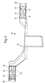
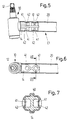
- FIGS. 1 to 14 Of the windshield wiper system, only the elements essential to the present invention are shown in FIGS. 1 to 14. With 10 and 11 two wiper bearings are designated, in which the wiper shafts 12 and 13 are rotatably mounted in a known manner via bearing bushes. These wiper bearings are made of die-cast zinc and each have an attachment 14, 15 in one piece, the spatial shape of which will be described later in connection with FIGS. 5 to 7.
- the wiper system includes tubular supports 20, 21 with a preferably circular cross section. An extension 14, 15 of a wiper bearing 10, 11 is inserted into one end E1 of these tubular supports 20, 21. In the other end E2 of these tubular supports 20, 21 are projections 30, 31 of a motor support part designated overall by 32.
- the support frame of this wiper system thus consists of two tubular supports 20, 21 and the motor support part 32, which is made as a die-cast part made of aluminum or zinc.
- the tubular supports 20, 21 are fixed in shape to the projections on the wiper bearing or the motor support part, which will be described later. It can be seen from FIGS. 1 and 2 that these tubular supports 20, 21 lie in different planes, the offset required for this being able to be implemented without difficulty by the correspondingly shaped motor support part 32.
- Fig. 2 are designated 33 mounting holes to which the actual drive motor of the wiper system is fixed by screwing.
- the output axis of the drive motor then extends along the line A.
- a straight line G is indicated, which connects the two wiper bearings 10, 11 to one another. It can be seen that the distance between this output axis A of this motor and this straight line G, which connects the wiper bearings 10, 11 to one another, is relatively small, so that there is no significant phase shift between the wiping movements of the two wipers.
- This is achieved by the arrangement of the lugs 30, 31, which can be seen in FIG. 2. It is important in this connection that the lugs 30, 31 are aligned in such a way that straight tubular supports 20, 21 are used can. This has the advantage that no expensive bending processes are required and that the stability of the connection also meets all requirements in the case of straight tubular supports.
- a fastening eye 34 is formed on the engine support part 32 produced as a die-cast part, which can generally be regarded as a fastening element and enables this engine support part 32 to be attached to the body of the motor vehicle, which is not shown in detail.
- each approach has two recesses 41 on both sides of a central web 40. Pipe sections 42 of the tubular support 20 are pressed into these recesses 41, which can be clearly seen in particular from FIG. 7.
- the tubular support 20, 21 is thus deformed in such a way that it adapts in sections to the non-circular contour of the projections 14, 15 and 30, 31, respectively. In this way, a positive connection between the approaches and the tubular supports is achieved.
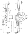
- FIGS. 8 to 11 show the drive motor 50, to which a gear housing 51 belongs, which is closed off by a cover 52. It is essential in the embodiment according to FIGS. 8 and 9 that the lugs 30, 31 are integrally formed on this gear housing 51, which can be made in a known manner from die-cast zinc, on which the ends E2 of the tubular carrier 20, 21 can be attached.
- the motor support part is, as it were, connected in one piece to a part of the drive motor 50, namely the gear housing 51.
- the fact could also be expressed in such a way that in this embodiment the motor support part - at least as a separate part - is omitted and by one appropriately designed gear housing 51 of the drive motor 50 is replaced.
- FIGS. 10 and 11 differs from the embodiment according to FIGS. 8 and 9 in that these projections 30, 31 are now formed on the cover 52, which is then also designed as a die-cast part.
- This gear housing could also be composed of two preferably identical gear housing halves, in which case each gear housing half should have such approaches so that this drive motor can be used as universally as possible for different wiper systems.
- the mounting of the output shaft 53 of the drive motor 50 can also be improved because storage is now possible on both sides of the worm wheel usually connected to the output shaft.
- the support frame for a wiper system with two wiper bearings consists of two tubular supports and an intermediate piece connecting these tubular supports in the form of a motor support part.
- This motor support part is designed as a die-cast part and can thus be designed in a simple manner so that subsequent pipe sections do not have to be bent if possible. Due to the use of straight tubes, this support frame is very torsion-resistant.
- a die-cast part as an intermediate piece between the two straight tubular supports, it is possible to create cost-effective wiper systems which can be assembled without difficulty even in complicated installation situations.
- the two wiper shafts can be driven directly from an engine crank, whereby phase shifts between the two wiping movements can be largely avoided.
- the manufacturing costs of such a wiper system are comparatively low.
- the wiper bearings made of die-cast zinc do not require any reworking at the point of attachment with the tubular support.
- the tube-like supports first have to be cut to length.
- the engine support part is also used as a die-cast part sprayed directly into the ready-to-use form. All parts are connected to one another by simply plugging them together, in which case the positive connections are then preferably produced in a single operation by non-cutting deformation of the tubular supports.
- changes are comparatively easy to carry out, because in many situations only the length of the tubular support has to be changed.
- a tubular support with a round cross section is used because the position of the wiper bearing can then be varied by rotation.
- square tubes could also be used as supports.
- the basic idea of the invention can be implemented using a separate motor support part, but designs are preferred in which this motor support part is not required as a separate part and the approaches for the dimensionally stable fixing of the tubular supports are molded directly onto a component of the gear housing of the drive motor.
- the gear housing takes over one supporting function of the frame. Since this gear housing is made of die-cast zinc, a fastening element, for example a fastening eye, can be molded on without additional effort, so that no additional components are required to fix the entire wiper system to the body.
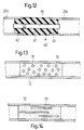
- 12 shows two parts 20a, 20b of a tubular support 20 which are connected to one another via an intermediate piece 60.
- This intermediate piece 60 is made of a noise-damping, frequency-filtering or noise-absorbing material, for example made of plastic. It consists of a spacer 61, from which projections 62, 63 extend on both sides, which are pressed into the tubular supports 20a, 20b. To stiffen the system, the spacer 61 and the side lugs 62, 63 can have a continuous bore 64 for the use of a reinforcing pin 65.
- the transmission of the tubular support 20 in two and the interposition of an intermediate piece 60, which serves as a noise-damping element significantly reduce noise transmission.
- FIGS. 13 and 14 the noise damping element 60 being here to a certain extent achieved by perforating the tubular support 20.
- 13 shows an embodiment in which this tubular support 20 has round openings 70 in a certain area.
- elongated openings 71 are provided.
- the tubular support 20 is filled with a noise-absorbing material 72, for example foamed.
- This measure allows resonance frequencies that arise to be largely filtered out and thus also attenuated, so that they are not transmitted to the body.
- care must be taken that the stability of the support frame is not inadmissibly reduced as a result.
Abstract
Claims (18)
- Système d'essuie-glace pour automobile , comprenant au moins un palier (10) d'essuie-glace, fixé sur l'une (E1) des extrémités d'une poutrelle tubulaire (20) reliée de façon rigide à une pièce support (32) de moteur prévue pour le moteur d'entraînement,
caractérisé en ce que l'autre extrémité (E2) de la poutrelle tubulaire (20) est emboîtée sur un appendice (30) formé sur la pièce support (32) du moteur, et est reliée à cet appendice par coopération de formes. - Système d'essuie-glace selon la revendication 1, caractérisé en ce que la pièce support (32) du moteur comporte un deuxième appendice (31), sur lequel est emboîtée une deuxième poutrelle tubulaire (21) prévue pour un deuxième palier (11) d'essuie-glace.
- Système d'essuie-glace selon la revendication 2, caractérisé en ce que les appendices (30, 31) sont disposés sur la pièce support (32) du moteur et sont orientés de manière telle que les paliers (10, 11) d'essuie-glace soient maintenus sur cette pièce support (32) du moteur par l'intermédiaire de poutrelles tubulaires droites (20, 21).
- Système d'essuie-glace selon l'une des revendications précédentes, caractérisé en ce que la pièce support (32) du moteur est réalisée sous forme d'une pièce moulée sous pression, notamment en aluminium ou en zinc.
- Système d'essuie-glace selon la revendication 4, caractérisé en ce que les appendices (30, 31) formés sur la pièce support (32) du moteur sont disposés et orientés de manière telle que la distance entre l'arbre (A) d'entraînement du moteur d'entraînement et une droite (G) reliant les paliers (10, 11 ) d'essuie-glace soit la plus petite possible.
- Système d'essuie-glace selon l'une des revendications 4 ou 5, caractérisé en ce que la pièce support (32) du moteur comporte un élément (34) de fixation destiné à être fixé sur la caisse de l'automobile.
- Système d'essuie-glace selon l'une des revendications précédentes, caractérisé en ce que chaque appendice (30, 31) comporte au moins un évidement (41), dans lequel on force une section du tube (20, 21), en vue d'obtenir une liaison par coopération de formes.
- Système d'essuie-glace selon la revendication 7, caractérisé en ce que chacun des paliers (10, 11) d'essuie-glace comporte également un appendice (14, 15) emboîté dans la poutrelle tubulaire associée (20, 21), et en ce que le type de liaison existant entre un appendice (14, 15) de palier d'essuie-glace et la poutrelle tubulaire (20, 21) correspond au type de liaison existant entre la poutrelle tubulaire (20, 21) et la pièce support (32) du moteur.
- Système d'essuie-glace selon l'une des revendications précédentes, caractérisé en ce que la pièce support (32) du moteur est réalisée d'un seul tenant avec une partie du moteur (50) d'entraînement.
- Système d'essuie-glace selon la revendication 9, caractérisé en ce que le moteur (50) d'entraînement comporte un carter (51) de transmission fermé par un couvercle (52), et en ce que la pièce support (32) du moteur, dont un appendice (30, 31) est emboîté dans une poutrelle tubulaire (20, 21), est réalisée d'un seul tenant avec le carter (51) de transmission.
- Système d'essuie-glace selon la revendication 9, caractérisé en ce que le moteur (50) d'entraînement comporte un carter (51) de transmission fermé par un couvercle (52), et en ce que le couvercle (52) est réalisé sous forme d'une pièce moulée sous pression, et en ce que la pièce support (32) du moteur, dont un appendice (30, 31) est emboîté dans une poutrelle tubulaire (20, 21), est réalisée d'un seul tenant avec le couvercle (52).
- Système d'essuie-glace selon la revendication 9, caractérisé en ce que le moteur d'entraînement comporte un carter de transmission comprenant deux demi-carters conçus de préférence de façon identique, et en ce que la pièce support du moteur, dont un appendice est emboîté dans une poutrelle tubulaire, est réalisée d'un seul tenant avec l'un des demi-carters.
- Système d'essuie-glace selon la revendication 12, caractérisé en ce que les deux demi-carters comportent des appendices permettant l'emboîtement des poutrelles tubulaires.
- Système d'essuie-glace notamment selon l'une au moins des revendications précédentes, caractérisé en ce qu'un élément insonorisant (60) est prévu entre le moteur d'entraînement et le palier d'essuie-glaces.
- Système d'essuie-glace selon la revendication 14, caractérisé en ce que la poutrelle tubulaire (20, 21) comporte un élément insonorisant (60).
- Système d'essuie-glace selon la revendication 15, caractérisé en ce que la poutrelle tubulaire (20) est divisée en deux parties, et en ce que les deux sections (20a, 20b) de la poutrelle sont reliées l'une à l'autre par l'intermédiaire d'un élément insonorisant (60).
- Système d'essuie-glace selon l'une des revendications 15 ou 16, caractérisé en ce que la poutrelle tubulaire (20, 21) comporte des zones pourvues de perforations (70, 71).
- Système d'essuie-glace selon l'une des revendications 15, 16 ou 17, caractérisé en ce que certaines zones de la poutrelle tubulaire (20, 21) sont remplies de matière insonorisante (72).
Applications Claiming Priority (2)
| Application Number | Priority Date | Filing Date | Title |
|---|---|---|---|
| DE3903976 | 1989-02-10 | ||
| DE3903976A DE3903976C2 (de) | 1989-02-10 | 1989-02-10 | Wischeranlage |
Publications (2)
| Publication Number | Publication Date |
|---|---|
| EP0409944A1 EP0409944A1 (fr) | 1991-01-30 |
| EP0409944B1 true EP0409944B1 (fr) | 1993-05-19 |
Family
ID=6373800
Family Applications (1)
| Application Number | Title | Priority Date | Filing Date |
|---|---|---|---|
| EP90902209A Expired - Lifetime EP0409944B1 (fr) | 1989-02-10 | 1990-02-06 | Systeme d'essuie-glace |
Country Status (7)
| Country | Link |
|---|---|
| US (1) | US5142941A (fr) |
| EP (1) | EP0409944B1 (fr) |
| JP (1) | JPH03503873A (fr) |
| BR (1) | BR9004952A (fr) |
| DE (1) | DE3903976C2 (fr) |
| ES (1) | ES2041527T3 (fr) |
| WO (1) | WO1990009299A1 (fr) |
Cited By (3)
| Publication number | Priority date | Publication date | Assignee | Title |
|---|---|---|---|---|
| DE19806855C2 (de) * | 1998-02-19 | 2002-06-27 | Bosch Gmbh Robert | Wischerträger |
| DE19829320B4 (de) * | 1998-07-01 | 2007-03-01 | Robert Bosch Gmbh | Rohrplatine |
| DE19712113B4 (de) * | 1997-03-22 | 2012-11-08 | Robert Bosch Gmbh | Lagerung eines Wischerantriebs |
Families Citing this family (35)
| Publication number | Priority date | Publication date | Assignee | Title |
|---|---|---|---|---|
| FR2667833B1 (fr) * | 1990-10-10 | 1995-07-07 | Valeo Systemes Dessuyage | Platine de support d'un moteur d'entrainement, notamment de moto-reducteur d'essuyage. |
| JPH086641Y2 (ja) * | 1990-11-02 | 1996-02-28 | 株式会社三ツ葉電機製作所 | パイプ式モジユラワイパ装置のパイプ締結構造 |
| FR2670730B1 (fr) * | 1990-12-21 | 1997-05-16 | Valeo Systemes Dessuyage | Platine d'essuie-glace, notamment pour vehicules automobiles. |
| JP2544115Y2 (ja) * | 1991-07-30 | 1997-08-13 | 株式会社ミツバ | モジユラ型ワイパ装置の躯体取付け構造 |
| DE4328651A1 (de) * | 1993-08-26 | 1995-03-02 | Teves Gmbh Alfred | Befestigungsmittel für eine Scheibenwischeranlage |
| FR2721883B1 (fr) * | 1994-06-30 | 1996-08-02 | Valeo Systemes Dessuyage | Platine-support pour un mecanisme d'essuie-glace |
| FR2724892B1 (fr) * | 1994-09-26 | 1996-12-13 | Valeo Systemes Dessuyage | Platine-support pour un ensemble d'essuie-glace |
| FR2724891B1 (fr) * | 1994-09-26 | 1996-12-13 | Valeo Systemes Dessuyage | Platine-support pour un mecanisme d'essuie-glace |
| JP2852004B2 (ja) * | 1994-12-08 | 1999-01-27 | 株式会社ミツバ | パイプ式モジュラワイパ装置におけるパイプ締結方法 |
| DE19539972A1 (de) * | 1995-10-27 | 1997-04-30 | Teves Gmbh Alfred | Antriebsvorrichtung für mindestens zwei Scheibenwischer eines Fahrzeuges |
| FR2745250B1 (fr) * | 1996-02-28 | 1998-05-07 | Valeo Systemes Dessuyage | Motoreducteur fixe par le couvercle |
| ES2166064T3 (es) * | 1996-03-18 | 2002-04-01 | Volkswagen Ag | Instalacion de limpiaparabrisas para un vehiculo y procedimiento para su fabricacion. |
| US5836042A (en) * | 1996-03-19 | 1998-11-17 | Acd Tridon Inc. | Modular windshield wiper drive support frame |
| EP0798181B1 (fr) * | 1996-03-26 | 2002-03-27 | Robert Bosch Gmbh | Palier d'entraínement d'un essuie-glace |
| EP0798183B1 (fr) * | 1996-03-26 | 2002-04-10 | Robert Bosch Gmbh | Platine de support tubulaire |
| DE19641951A1 (de) * | 1996-10-11 | 1998-04-16 | Bosch Gmbh Robert | Scheibenwischeranlage |
| FR2763296B1 (fr) * | 1997-05-15 | 1999-06-11 | Valeo Systemes Dessuyage | Systeme d'essuyage comportant un palier de guidage de l'arbre d'entrainement de l'essuie-glace |
| DE19745690C2 (de) * | 1997-10-16 | 2000-03-02 | Bosch Gmbh Robert | Antriebsvorrichtung für eine Wischanlage, insbesondere für Scheiben an Kraftfahrzeugen |
| JP4014657B2 (ja) | 1998-04-29 | 2007-11-28 | ローベルト ボツシユ ゲゼルシヤフト ミツト ベシユレンクテル ハフツング | 管付きベースプレート |
| DE19820798A1 (de) | 1998-05-09 | 1999-11-11 | Bosch Gmbh Robert | Scheibenwischeranlage |
| DE19820789A1 (de) | 1998-05-09 | 1998-12-03 | Detlef Brommer | Kontrollverfahren für Werkstücke in der Industrie, exakte Kontrolle der Richtigkeit, Vollzähligkeit, Lage, Anordnung und evtl. Beschädigungen von Werkstücken, Maschinen- und Motorenteilen i. d. industriellen Fertigung |
| FR2780365A1 (fr) * | 1998-06-30 | 1999-12-31 | Valeo Systemes Dessuyage | Systeme d'essuyage pour vehicule automobile comportant un palier standardise a portee spherique |
| US6343403B1 (en) * | 1998-07-24 | 2002-02-05 | Asmo Co., Ltd. | Wiper device, and method of manufacturing hollow frame for wiper device |
| DE19945367A1 (de) * | 1999-09-22 | 2001-04-19 | Volkswagen Ag | Befestigungsanordnung für eine Scheibenwischeranlage |
| KR100472708B1 (ko) * | 2000-04-19 | 2005-03-08 | 아스모 가부시키가이샤 | 와이퍼 장치 |
| DE10055426B4 (de) * | 2000-11-09 | 2010-08-05 | Robert Bosch Gmbh | Wischerlagergehäuse und Verfahren zum Herstellen eines Wischerlagergehäuses |
| DE10250843B4 (de) * | 2002-10-31 | 2017-02-16 | Valeo Wischersysteme Gmbh | Wischlager für eine Wischerwelle einer Scheibenwischanlage sowie Verfahren zum Herstellen einer Verbindung zwischen einem Wischlager und einem Halterohr einer Scheibenwischanlage |
| DE102004009303A1 (de) * | 2004-02-26 | 2005-09-15 | Robert Bosch Gmbh | Scheibenwischvorrichtung, insbesondere für ein Kraftfahrzeug |
| DE102004063179A1 (de) * | 2004-12-29 | 2006-07-13 | Robert Bosch Gmbh | Scheibenwischvorrichtung |
| JP4938526B2 (ja) | 2007-03-28 | 2012-05-23 | 株式会社ミツバ | 車両用ワイパ装置 |
| DE102007055113B4 (de) * | 2007-11-19 | 2017-05-24 | Volkswagen Ag | Scheibenwischeranlage an einem Fahrzeug |
| US8281452B2 (en) * | 2008-12-11 | 2012-10-09 | Asmo Co., Ltd. | Wiper device |
| DE102010029105B4 (de) * | 2009-10-21 | 2018-01-11 | Robert Bosch Gmbh | Scheibenwischervorrichtung |
| WO2012157646A1 (fr) | 2011-05-19 | 2012-11-22 | アスモ 株式会社 | Dispositif d'essuie-glace, procédé de fabrication de dispositif d'essuie-glace et dispositif permettant de fabriquer un dispositif d'essuie-glace |
| US9446740B2 (en) * | 2013-09-16 | 2016-09-20 | Mitsuba Corporation | Windshield wiper assembly |
Family Cites Families (15)
| Publication number | Priority date | Publication date | Assignee | Title |
|---|---|---|---|---|
| US1747284A (en) * | 1928-06-22 | 1930-02-18 | Carroll H Berill | Windshield wiper |
| US1812918A (en) * | 1929-02-12 | 1931-07-07 | E A Lab Inc | Windshield wiper |
| US1828713A (en) * | 1929-03-11 | 1931-10-20 | Trico Products Corp | Dual wiper windshield cleaner |
| US1839175A (en) * | 1929-08-03 | 1931-12-29 | Trico Products Corp | Windshield cleaner |
| US1913308A (en) * | 1930-09-18 | 1933-06-06 | Trico Products Corp | Windshield cleaner |
| US2670492A (en) * | 1948-03-03 | 1954-03-02 | Clinton R Boothby | Electric windshield wiper |
| GB677147A (en) * | 1948-11-04 | 1952-08-13 | Trico Products Corp | Improvements in or relating to a windshield wiper unit |
| US3188644A (en) * | 1961-06-12 | 1965-06-08 | Collins Radio Co | Weighted device for damping out vibration in an antenna element |
| DE7434119U (de) * | 1974-10-11 | 1975-02-06 | Rau G Gmbh | Antrieb für Scheibenwischer in Fahrzeugen |
| DE2920899A1 (de) * | 1979-05-23 | 1981-01-22 | Rau Swf Autozubehoer | Scheibenwischeranlage, insbesondere fuer kraftfahrzeuge |
| JPS58149523A (ja) * | 1982-03-01 | 1983-09-05 | Nissan Motor Co Ltd | マニユアルトランスミツシヨンのリモ−トコントロ−ル機構 |
| US4706788A (en) * | 1985-04-15 | 1987-11-17 | Melles Griot, Irvine Company | Vibration damped apparatus |
| DE3531858C1 (de) * | 1985-09-06 | 1986-11-13 | Daimler-Benz Ag, 7000 Stuttgart | Scheibenwischeranlage,insbesondere fuer Kraftfahrzeuge |
| US4913410A (en) * | 1987-01-07 | 1990-04-03 | Marshall Robert L | Particle for vibration damping |
| JPH0751953Y2 (ja) * | 1988-05-18 | 1995-11-29 | 自動車電機工業株式会社 | ワイパ装置 |
-
1989
- 1989-02-10 DE DE3903976A patent/DE3903976C2/de not_active Expired - Lifetime
-
1990
- 1990-02-06 WO PCT/EP1990/000191 patent/WO1990009299A1/fr active IP Right Grant
- 1990-02-06 ES ES199090902209T patent/ES2041527T3/es not_active Expired - Lifetime
- 1990-02-06 US US07/585,153 patent/US5142941A/en not_active Expired - Lifetime
- 1990-02-06 JP JP2502599A patent/JPH03503873A/ja active Pending
- 1990-02-06 BR BR909004952A patent/BR9004952A/pt not_active IP Right Cessation
- 1990-02-06 EP EP90902209A patent/EP0409944B1/fr not_active Expired - Lifetime
Cited By (3)
| Publication number | Priority date | Publication date | Assignee | Title |
|---|---|---|---|---|
| DE19712113B4 (de) * | 1997-03-22 | 2012-11-08 | Robert Bosch Gmbh | Lagerung eines Wischerantriebs |
| DE19806855C2 (de) * | 1998-02-19 | 2002-06-27 | Bosch Gmbh Robert | Wischerträger |
| DE19829320B4 (de) * | 1998-07-01 | 2007-03-01 | Robert Bosch Gmbh | Rohrplatine |
Also Published As
| Publication number | Publication date |
|---|---|
| EP0409944A1 (fr) | 1991-01-30 |
| DE3903976C2 (de) | 1997-07-03 |
| DE3903976A1 (de) | 1990-08-16 |
| US5142941A (en) | 1992-09-01 |
| BR9004952A (pt) | 1991-08-06 |
| ES2041527T3 (es) | 1993-11-16 |
| WO1990009299A1 (fr) | 1990-08-23 |
| JPH03503873A (ja) | 1991-08-29 |
Similar Documents
| Publication | Publication Date | Title |
|---|---|---|
| EP0409944B1 (fr) | Systeme d'essuie-glace | |
| DE602005004734T2 (de) | Elektrische Servolenkung | |
| EP0799142B1 (fr) | Systeme d'essuie-glaces pourvu d'un element de fixation amortissant le bruit et les vibrations | |
| EP0918671B1 (fr) | Unite d'entrainement electrique | |
| DE102006006925A1 (de) | Spindelantrieb, insbesondere zum Verstellen eines beweglichen Teils im Kraftfahrzeug | |
| EP0316832A1 (fr) | Elément de transmission pour installation d'essuyage de véhicules automobiles et son procédé de fabrication | |
| DE102017205721B4 (de) | Getriebeeinheit für ein Kraftfahrzeug | |
| EP1732785A1 (fr) | Ensemble coussin gonflable de protection, ainsi que train d'engrenages et procede pour faire fonctionner un tel ensemble | |
| DE102015000027A1 (de) | Lenksäule mit flexibel montierbarem Lagersitz | |
| EP1104368B1 (fr) | Platine | |
| DE102006009576A1 (de) | Spindelantrieb, insbesondere zum Verstellen eines beweglichen Teils im Kraftfahzeug | |
| EP0572821B1 (fr) | Colonne de direction de voiture | |
| EP2030869B1 (fr) | Support en tant que traverse ou longeron dans un véhicule automobile | |
| EP0435969B1 (fr) | Commande oscillante, notamment pour essuie-glace de vehicules a moteur | |
| EP2059422B1 (fr) | Système d'essuie-glace | |
| WO1997016332A1 (fr) | Dispositif de commande d'au moins deux essuie-glaces d'un vehicule | |
| DE10059148A1 (de) | Kegelradmechanismus und elektrische Lenkhilfe, die diesen verwendet | |
| DE10016883A1 (de) | Kraftfahrzeug | |
| EP1647464A2 (fr) | Dispositif de réglage de la hauteur d'une colonne de direction | |
| EP1631471B1 (fr) | Support de boite de vitesses pour le montage d'une boite de vitesses, et boite de vitesses pourvue d'un tel support | |
| DE4217123C2 (de) | Rückenlehne für Fahrzeugsitze, insbesondere Kraftfahrzeugsitze | |
| EP0829399A2 (fr) | Dispositif d'entraînement, en particulier pour essuie-glace de véhicule automobile | |
| EP1565358B1 (fr) | Systeme d'essuie-glace | |
| DE102017205724A1 (de) | Getriebeeinheit für ein Kraftfahrzeug | |
| EP3548361A1 (fr) | Squelette de volant et volant de véhicule doté d'un tel squelette de volant |
Legal Events
| Date | Code | Title | Description |
|---|---|---|---|
| PUAI | Public reference made under article 153(3) epc to a published international application that has entered the european phase |
Free format text: ORIGINAL CODE: 0009012 |
|
| 17P | Request for examination filed |
Effective date: 19901024 |
|
| AK | Designated contracting states |
Kind code of ref document: A1 Designated state(s): ES FR GB IT SE |
|
| 17Q | First examination report despatched |
Effective date: 19920401 |
|
| GRAA | (expected) grant |
Free format text: ORIGINAL CODE: 0009210 |
|
| AK | Designated contracting states |
Kind code of ref document: B1 Designated state(s): ES FR GB IT SE |
|
| ITF | It: translation for a ep patent filed |
Owner name: DE DOMINICIS & MAYER S.R.L. |
|
| ET | Fr: translation filed | ||
| GBT | Gb: translation of ep patent filed (gb section 77(6)(a)/1977) |
Effective date: 19930722 |
|
| PLBE | No opposition filed within time limit |
Free format text: ORIGINAL CODE: 0009261 |
|
| STAA | Information on the status of an ep patent application or granted ep patent |
Free format text: STATUS: NO OPPOSITION FILED WITHIN TIME LIMIT |
|
| 26N | No opposition filed | ||
| REG | Reference to a national code |
Ref country code: FR Ref legal event code: TP |
|
| EAL | Se: european patent in force in sweden |
Ref document number: 90902209.7 |
|
| REG | Reference to a national code |
Ref country code: ES Ref legal event code: PC2A Owner name: ITT AUTOMOTIVE EUROPE GMBH |
|
| REG | Reference to a national code |
Ref country code: GB Ref legal event code: IF02 |
|
| PGFP | Annual fee paid to national office [announced via postgrant information from national office to epo] |
Ref country code: SE Payment date: 20040119 Year of fee payment: 15 |
|
| PGFP | Annual fee paid to national office [announced via postgrant information from national office to epo] |
Ref country code: GB Payment date: 20040130 Year of fee payment: 15 |
|
| PG25 | Lapsed in a contracting state [announced via postgrant information from national office to epo] |
Ref country code: IT Free format text: LAPSE BECAUSE OF NON-PAYMENT OF DUE FEES;WARNING: LAPSES OF ITALIAN PATENTS WITH EFFECTIVE DATE BEFORE 2007 MAY HAVE OCCURRED AT ANY TIME BEFORE 2007. THE CORRECT EFFECTIVE DATE MAY BE DIFFERENT FROM THE ONE RECORDED. Effective date: 20050206 Ref country code: GB Free format text: LAPSE BECAUSE OF NON-PAYMENT OF DUE FEES Effective date: 20050206 |
|
| PG25 | Lapsed in a contracting state [announced via postgrant information from national office to epo] |
Ref country code: SE Free format text: LAPSE BECAUSE OF NON-PAYMENT OF DUE FEES Effective date: 20050207 |
|
| GBPC | Gb: european patent ceased through non-payment of renewal fee |
Effective date: 20050205 |
|
| EUG | Se: european patent has lapsed | ||
| PGFP | Annual fee paid to national office [announced via postgrant information from national office to epo] |
Ref country code: ES Payment date: 20090220 Year of fee payment: 20 |
|
| PGFP | Annual fee paid to national office [announced via postgrant information from national office to epo] |
Ref country code: FR Payment date: 20090227 Year of fee payment: 20 |
|
| REG | Reference to a national code |
Ref country code: ES Ref legal event code: FD2A Effective date: 20100208 |
|
| PG25 | Lapsed in a contracting state [announced via postgrant information from national office to epo] |
Ref country code: ES Free format text: LAPSE BECAUSE OF EXPIRATION OF PROTECTION Effective date: 20100208 |