EP0409924B1 - Abgasleitung für eine mehrzylindrige kolbenbrennkraftmaschine - Google Patents
Abgasleitung für eine mehrzylindrige kolbenbrennkraftmaschine Download PDFInfo
- Publication number
- EP0409924B1 EP0409924B1 EP90900754A EP90900754A EP0409924B1 EP 0409924 B1 EP0409924 B1 EP 0409924B1 EP 90900754 A EP90900754 A EP 90900754A EP 90900754 A EP90900754 A EP 90900754A EP 0409924 B1 EP0409924 B1 EP 0409924B1
- Authority
- EP
- European Patent Office
- Prior art keywords
- section
- housing
- plug
- internal
- combustion engine
- Prior art date
- Legal status (The legal status is an assumption and is not a legal conclusion. Google has not performed a legal analysis and makes no representation as to the accuracy of the status listed.)
- Expired - Lifetime
Links
Images

Classifications
-
- F—MECHANICAL ENGINEERING; LIGHTING; HEATING; WEAPONS; BLASTING
- F01—MACHINES OR ENGINES IN GENERAL; ENGINE PLANTS IN GENERAL; STEAM ENGINES
- F01N—GAS-FLOW SILENCERS OR EXHAUST APPARATUS FOR MACHINES OR ENGINES IN GENERAL; GAS-FLOW SILENCERS OR EXHAUST APPARATUS FOR INTERNAL-COMBUSTION ENGINES
- F01N13/00—Exhaust or silencing apparatus characterised by constructional features
- F01N13/08—Other arrangements or adaptations of exhaust conduits
- F01N13/10—Other arrangements or adaptations of exhaust conduits of exhaust manifolds
-
- F—MECHANICAL ENGINEERING; LIGHTING; HEATING; WEAPONS; BLASTING
- F02—COMBUSTION ENGINES; HOT-GAS OR COMBUSTION-PRODUCT ENGINE PLANTS
- F02B—INTERNAL-COMBUSTION PISTON ENGINES; COMBUSTION ENGINES IN GENERAL
- F02B75/00—Other engines
- F02B75/16—Engines characterised by number of cylinders, e.g. single-cylinder engines
- F02B75/18—Multi-cylinder engines
- F02B75/22—Multi-cylinder engines with cylinders in V, fan, or star arrangement
Definitions
- the invention relates to an exhaust pipe for a multi-cylinder piston internal combustion engine according to the preamble of claim 1.
- Such an exhaust pipe has a very low surface temperature, so that a piston internal combustion engine equipped with it meets the requirements for unattended operation.
- a generic exhaust pipe is known from DE -C1- 34 45 916.
- the plug connection interacting with the housing at the exhaust outlet of each cylinder has the task of fixing the section of the inner line in the longitudinal and circumferential directions.
- the oscillation excitation of the inner line emanating from the pulsating exhaust gas flow cannot be prevented by the known arrangement.
- the plug-in connection has play between the inner and outer part, as a result of which vibration-reducing support of the sections of the inner line is not possible.
- the support of the sections of the inner line by the plug connection approximately perpendicular to its longitudinal extension on The housing is ineffective when the exhaust pipe is cold, since there is play between the receptacle and the pin.
- the support only starts when the play in the plug connection is eliminated due to the difference in thermal expansion. In this way, the sections of the inner line are only supported against the housing when an operating temperature at which vibration excitation would be critical is reached. In contrast, during the heating phase of the exhaust pipe, the thermal expansion of the sections of the inner pipe is not impeded.
- the plug connection is self-adjusting, that the plug connection of the inner line is easy to assemble and that, in particular when the exhaust line is arranged with two oppositely opening exhaust gas outlets from cylinders, the vibration excitation of the inner line is avoided.
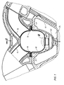
- the lower part of a liquid-cooled housing for receiving an inner line formed from sections 18 for the exhaust gases of a multi-cylinder piston internal combustion engine is formed by the space 14 of the cylinder crankcase 13 between the rows of cylinders arranged in a V-shape.
- the length of the sections 18 of the inner line corresponds approximately to the cylinder spacing of the piston internal combustion engine.
- Each section 18 of the inner line has two exhaust gas inlet openings 16 located approximately in the center of its length, into each of which an exhaust pipe 15 of one cylinder of each row of cylinders opens at an angle.
- the sections 18 of the inner line are fastened to the cylinder crankcase 13 via flanges 17 approximately centrally to their length.
- the end faces of the sections 18 face each other with a distance 19 which, due to thermal expansion at operating temperature, is reduced almost to zero.
- the alternating from the exhaust pipe 15 obliquely for attachment to the flanges 17 on the sections 18 pulsating exhaust gas flow causes a vibration excitation of the inner line.
- vibrations of the inner line can have an adverse effect on operation when the operating temperature reaches approx. 700 ° C.
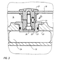
- each section 18 of the inner line is connected to the cylinder crankcase 13 by a plug connection 20 perpendicular to its longitudinal extent.
- the plug connection 20 consists of a collar bushing 21 inserted and fastened in the cooled wall 22 of the cylinder crankcase 13 and a pin 23 fastened to the section 18.
- the collar bushing 21 projects with its bottom into the cooling channel 24 of the cylinder crankcase 13 and is thereby intensive chilled.
- the pin 23, which corresponds to the receiving bore 25 of the collar bushing 21, is detachably fastened to the wall of the section 18 by means of a screw 26 and anvil 27.
- the pin 23 When the piston internal combustion engine is operating, the pin 23 is heated very strongly by the exhaust gas heat from the inner line. As a result of the temperature increase, the diameter of the pin 23 increases due to thermal expansion. Due to the intensive cooling, the heating of the flange bushing 21 is less than that of the pin 23. This results in a difference in thermal expansion, which consumes the game initially present and leads to a firm fit of the pin 23 in the flange bushing 21. As a result, the vibration-reducing support of the sections 18 of the inner line against the housing occurs when the inner line reaches its critical operating temperature. When the exhaust pipe cools down during interruptions in operation, the tight fit of the pin 23 is released again.
- the entry of the tight fit of the plug-in connection for a desired temperature level can be determined by a suitable choice of the initial play between the collar bushing 21 and the pin 23.
Landscapes
- Engineering & Computer Science (AREA)
- Chemical & Material Sciences (AREA)
- Combustion & Propulsion (AREA)
- Mechanical Engineering (AREA)
- General Engineering & Computer Science (AREA)
- Exhaust Silencers (AREA)
- Quick-Acting Or Multi-Walled Pipe Joints (AREA)
Abstract
Description
- Die Erfindung bezieht sich auf eine Abgasleitung für eine mehrzylindrige Kolbenbrennkraftmaschine nach dem Oberbegriff von Patentanspruch 1. Eine derartige Abgasleitung hat eine sehr niedrige Oberflächentemperatur, so daß eine damit ausgerüstete Kolbenbrennkraftmaschine den Anforderungen für unbeaufsichtigten Betrieb entspricht.
- Eine gattungsgemäße Abgasleitung ist aus der DE -C1- 34 45 916 bekannt. Die mit dem Gehäuse zusammenwirkende Steckverbindung am Abgasaustritt jeden Zylinders hat die Aufgabe, jeweils den Abschnitt der inneren Leitung in Längs- und Umfangsrichtung zu fixieren. Die von der pulsierenden Abgasströmung ausgehende Schwingungserregung der inneren Leitung kann von der bekannten Anordnung nicht verhindert werden. Die Steckverbindung weist nämlich bei allen Betriebszuständen Spiel zwischen Innen- und Außenteil auf, wodurch eine schwingungsmindernde Abstützung der Abschnitte der inneren Leitung nicht möglich ist.
- Es ist deshalb Aufgabe der Erfindung, die Abgasleitung einer mehrzylindrigen Kolbenbrennkraftmaschine mit einer die Abgase führenden inneren Leitung und einem diese Leitung mit Abstand umgebenden gasdichten Gehäuse derart weiterzuentwickeln, daß eine Schwingungserregung der inneren Leitung durch die Abgasströmung vermieden wird.
- Diese Aufgabe ist erfindungsgemäß mit den kennzeichnenden Merkmalen von Anspruch 1 gelöst und mit den Merkmalen der Ansprüche 2 und 3 weiter ausgestaltet.
- Die Abstützung der Abschnitte der inneren Leitung durch die Steckverbindung etwa senkrecht zu ihrer Längserstreckung am Gehäuse ist im kalten Zustand der Abgasleitung unwirksam, da dann zwischen Aufnahme und Zapfen Spiel vorhanden ist. Die Abstützung setzt erst ein, wenn infolge von Wärmedehnungsdifferenz das Spiel in der Steckverbindung aufgehoben ist. Auf diese Weise sind die Abschnitte der inneren Leitung erst bei Erreichen einer Betriebstemperatur, bei der eine Schwingungserregung kritisch wäre, gegen das Gehäuse abgestützt. Während der Erwärmungsphase der Abgasleitung ist die Wärmedehnung der Abschnitte der inneren Leitung dagegen nicht behindert.
- Die mit der Erfindung erzielten Vorteile bestehen darin, daß die Steckverbindung selbsteinstellend wirkt, daß die Steckverbindung der inneren Leitung einfach zu montieren ist und daß insbesondere bei Anordnung der Abgasleitung mit zwei gegenüberliegend schräg einmündenden Abgasaustritten von Zylindern die Schwingungserregung der inneren Leitung vermieden ist.
- Ein Ausführungsbeispiel der Erfindung ist in der Zeichnung dargestellt und wird nachstehend näher beschrieben. Es zeigen:
- Fig. 1 Teillängsschnitt einer Kolbenbrennkraftmaschine nach Linie I-I in Figur 2;
- Fig. 2 Teilquerschnitt einer Kolbenbrennkraftmaschine nach Linie II-II in Figur 1;
- Fig. 3 Detaildarstellung einer Steckverbindung nach Einzelheit III in Figur 1.
- Das Unterteil eines flüssigkeitsgekühlten Gehäuses zur Aufnahme einer aus Abschnitten 18 gebildeten inneren Leitung für die Abgase einer mehrzylindrigen Kolbenbrennkraftmaschine wird durch den Raum 14 des Zylinder-Kurbelgehäuses 13 zwischen den V-förmig angeordneten Zylinderreihen gebildet. Die Länge der Abschnitte 18 der inneren Leitung entspricht etwa dem Zylinderabstand der Kolbenbrennkraftmaschine. Jeder Abschnitt 18 der inneren Leitung weist etwa mittig zu seiner Länge zwei sich gegenüberliegende Abgaseintrittsöffnung 16 auf, in die jeweils ein Abgasstutzen 15 eines Zylinders jeder Zylinderreihe schräg mündet. Die Abschnitte 18 der inneren Leitung sind über Flansche 17 etwa mittig zu ihrer Länge am Zylinder-Kurbelgehäuse 13 befestigt. Die Stirnseiten der Abschnitte 18 stehen sich mit einem Abstand 19 gegenüber, der sich infolge Wärmedehnung bei Betriebstemperatur nahezu auf Null reduziert. Die abwechselnd aus den Abgasstutzen 15 schräg zur Befestigung an den Flanschen 17 auf die Abschnitte 18 auftreffende pulsierende Abgasströmung verursacht eine Schwingungserregung der inneren Leitung. Infolge abnehmender Werkstoffestigkeit bei starker Erwärmung eines Bauteils können sich Schwingungen der inneren Leitung bei Erreichen der Betriebstemperatur von ca. 700 °C betriebsgefährdend auswirken.
- Etwa gegenüberliegend den Abgaseintrittsöffnungen 16 ist jeder Abschnitt 18 der inneren Leitung, senkrecht zu seiner Längserstreckung durch eine Steckverbindung 20 mit dem Zylinder-Kurbelgehäuse 13 verbunden. Die Steckverbindung 20 besteht aus einer in die gekühlte Wand 22 des Zylinder-Kurbelgehäuses 13 eingesetzten und befestigten Bundbuchse 21 sowie einem am Abschnitt 18 befestigten Zapfen 23. Die Bundbuchse 21 ragt mit ihrem Boden in den Kühlkanal 24 des Zylinder-Kurbelgehäuses 13 und wird dadurch intensiv gekühlt. Der Zapfen 23, der mit der Aufnahmebohrung 25 der Bundbuchse 21 korrespondiert, ist an der Wand des Abschnittes 18 mittels einer Schraube 26 und Gegenhalter 27 lösbar befestigt.
- Im kalten Zustand der Abgasleitung besteht zwischen Aufnahmebohrung 25 in der Bundbuchse 21 und dem Zapfen 23 eine Spielpassung, die eine einfache Montage der inneren Leitung gewährleistet.
- Bei Betrieb der Kolbenbrennkraftmaschine wird der Zapfen 23 durch die Abgaswärme von der inneren Leitung her sehr stark erwärmt. Infolge der Temperaturerhöhung vergrößert sich der Durchmesser des Zapfens 23 durch Wärmedehnung. Die Erwärmung der Bundbuchse 21 ist aufgrund der intensiven Kühlung geringer als die des Zapfens 23. Daraus resultiert eine Wärmedehnungsdifferenz, die das anfangs vorhandene Spiel aufzehrt und zu einem festen Sitz des Zapfens 23 in der Bundbuchse 21 führt. Dadurch tritt die schwingungsmindernde Abstützung der Abschnitte 18 der inneren Leitung gegenüber dem Gehäuse dann ein, wenn die innere Leitung ihre kritische Betriebstemperatur erreicht. Bei Abkühlung der Abgasleitung während Betriebsunterbrechungen löst sich der Festsitz des Zapfens 23 wieder.
- Durch geeignete Wahl des Anfangsspieles zwischen Bundbuchse 21 und Zapfen 23 kann der Eintritt des Festsitzes der Steckverbindung für ein gewünschtes Temperaturniveau bestimmt werden.
Claims (3)
- Abgasleitung für eine mehrzylindrige Kolbenbrennkraftmaschine mit wenigstens einer die Abgase führenden inneren Leitung und einem die innere Leitung mit Abstand umgebenden gasdichten, gekühlten Gehäuse (13), wobei die am umgebenden Gehäuse (13) befestigte innere Leitung aus einzelnen, unter Belassung von Dehnfugen, aneinandergereihten Abschnitten (18) besteht, die Länge eines Abschnittes (18) etwa dem Zylinderabstand der Kolbenbrennkraftmaschine entspricht und jeder Abschnitt (18) auf etwa der Hälfte seiner Länge am Außenumfang eine mit dem Gehäuse (13) zusammenwirkende, spielbehaftete Steckverbindung (20) aufweist, dadurch gekennzeichnet, daß die Steckverbindung (20) etwa gegenüberliegend der Einmündung eines Abgasstutzens (15) eines mit dem Abschnitt (18) zusammenwirkenden Zylinders angeordnet ist, daß die Steckverbindung (20) aus einer im Gehäuse (13) gekühlt angeordneten Aufnahme (21) und einem mit dem Abschnitt (18) der inneren Leitung verbundenen, korrespondierenden Zapfen (23) besteht.
- Abgasleitung nach Anspruch 1, dadurch gekennzeichnet, daß die Aufnahme eine dichtend, in eine Öffnung der gekühlten inneren Wand (22) des Gehäuses (13) eingesetzte Bundbuchse (21) mit Boden ist.
- Abgasleitung nach Anspruch 1, dadurch gekennzeichnet, daß der Zapfen (23) mittels Schraubenverbindung lösbar am Abschnitt (18) der inneren Leitung befestigt ist.
Priority Applications (1)
| Application Number | Priority Date | Filing Date | Title |
|---|---|---|---|
| AT90900754T ATE85402T1 (de) | 1989-01-13 | 1989-12-14 | Abgasleitung fuer eine mehrzylindrige kolbenbrennkraftmaschine. |
Applications Claiming Priority (2)
| Application Number | Priority Date | Filing Date | Title |
|---|---|---|---|
| DE3900830A DE3900830C1 (de) | 1989-01-13 | 1989-01-13 | |
| DE3900830 | 1989-01-13 |
Publications (2)
| Publication Number | Publication Date |
|---|---|
| EP0409924A1 EP0409924A1 (de) | 1991-01-30 |
| EP0409924B1 true EP0409924B1 (de) | 1993-02-03 |
Family
ID=6372005
Family Applications (1)
| Application Number | Title | Priority Date | Filing Date |
|---|---|---|---|
| EP90900754A Expired - Lifetime EP0409924B1 (de) | 1989-01-13 | 1989-12-14 | Abgasleitung für eine mehrzylindrige kolbenbrennkraftmaschine |
Country Status (9)
| Country | Link |
|---|---|
| US (1) | US5056310A (de) |
| EP (1) | EP0409924B1 (de) |
| JP (1) | JPH0711246B2 (de) |
| KR (1) | KR940007227B1 (de) |
| CN (1) | CN1012751B (de) |
| DE (2) | DE3900830C1 (de) |
| ES (1) | ES2017575A6 (de) |
| RU (1) | RU1828500C (de) |
| WO (1) | WO1990008250A1 (de) |
Families Citing this family (5)
| Publication number | Priority date | Publication date | Assignee | Title |
|---|---|---|---|---|
| DE4224317C1 (de) * | 1992-07-23 | 1993-12-16 | Mtu Friedrichshafen Gmbh | Einrichtung zur Befestigung eines Gasführungskanals innerhalb eines Gehäuses einer Abgasleitung |
| DE4229467A1 (de) * | 1992-09-03 | 1994-03-10 | Mtu Friedrichshafen Gmbh | Lagereinrichtung für die Abgassammelleitung einer Brennkraftmaschine |
| DE102006012365B4 (de) * | 2006-03-17 | 2014-02-13 | Man Diesel & Turbo Se | Abgasleitungssystem für mehrzylindrige Gas- und Dieselmotoren |
| CN101473117B (zh) * | 2006-06-21 | 2010-11-17 | 戴姆勒股份公司 | 排气歧管 |
| WO2013129479A1 (ja) * | 2012-02-29 | 2013-09-06 | 日立金属株式会社 | 低融点な電気アルミニウムめっき用めっき液の調製方法、電気アルミニウムめっき用めっき液、アルミニウム箔の製造方法、および、電気アルミニウムめっき用めっき液の融点を低下させる方法 |
Family Cites Families (7)
| Publication number | Priority date | Publication date | Assignee | Title |
|---|---|---|---|---|
| JPS4844684B1 (de) * | 1970-01-14 | 1973-12-26 | ||
| JPS5326250B2 (de) * | 1973-12-29 | 1978-08-01 | ||
| DE2653263C3 (de) * | 1976-11-24 | 1983-05-11 | Mtu Motoren- Und Turbinen-Union Friedrichshafen Gmbh, 7990 Friedrichshafen | Abgasleitung |
| DE3150001C2 (de) * | 1981-12-17 | 1986-08-14 | Mtu Motoren- Und Turbinen-Union Friedrichshafen Gmbh, 7990 Friedrichshafen | Kolbenbrennkraftmaschine mit Aufladung |
| DE3445916C1 (de) * | 1984-12-17 | 1986-07-24 | Mtu Motoren- Und Turbinen-Union Friedrichshafen Gmbh, 7990 Friedrichshafen | Abgasleitung für eine aufgeladene, mehrzylindrige Kolben-Brennkraftmaschine |
| DE3631312C1 (de) * | 1986-09-13 | 1987-07-02 | Mtu Friedrichshafen Gmbh | Einrichtung zur Halterung von Abgasleitungen |
| DE3635478C1 (de) * | 1986-10-18 | 1988-02-11 | Mtu Friedrichshafen Gmbh | Abgasleitung fuer eine aufgeladene,mehrzylindrige Brennkraftmaschine |
-
1989
- 1989-01-13 DE DE3900830A patent/DE3900830C1/de not_active Expired
- 1989-12-01 ES ES8904108A patent/ES2017575A6/es not_active Expired - Lifetime
- 1989-12-14 JP JP2500958A patent/JPH0711246B2/ja not_active Expired - Lifetime
- 1989-12-14 US US07/499,303 patent/US5056310A/en not_active Expired - Fee Related
- 1989-12-14 WO PCT/DE1989/000771 patent/WO1990008250A1/de not_active Ceased
- 1989-12-14 EP EP90900754A patent/EP0409924B1/de not_active Expired - Lifetime
- 1989-12-14 DE DE9090900754T patent/DE58903471D1/de not_active Expired - Fee Related
- 1989-12-14 KR KR1019900702019A patent/KR940007227B1/ko not_active Expired - Fee Related
- 1989-12-30 CN CN89109742A patent/CN1012751B/zh not_active Expired
-
1990
- 1990-09-10 RU SU904830988A patent/RU1828500C/ru active
Also Published As
| Publication number | Publication date |
|---|---|
| ES2017575A6 (es) | 1991-02-16 |
| US5056310A (en) | 1991-10-15 |
| JPH03500441A (ja) | 1991-01-31 |
| DE58903471D1 (de) | 1993-03-18 |
| RU1828500C (ru) | 1993-07-15 |
| CN1012751B (zh) | 1991-06-05 |
| WO1990008250A1 (de) | 1990-07-26 |
| KR940007227B1 (ko) | 1994-08-10 |
| CN1045154A (zh) | 1990-09-05 |
| EP0409924A1 (de) | 1991-01-30 |
| JPH0711246B2 (ja) | 1995-02-08 |
| KR910700396A (ko) | 1991-03-15 |
| DE3900830C1 (de) | 1989-11-02 |
Similar Documents
| Publication | Publication Date | Title |
|---|---|---|
| DE69408424T2 (de) | Integraler Gussdiffusor für einen Katalysator | |
| EP1270891B1 (de) | Vorrichtung zur Befestigung eines Abgasturboladers an einem Abgaskrümmer einer Brennkraftmaschine | |
| DE3032253C2 (de) | Verbrennungsmotor, insbesondere Dieselmotor | |
| WO1999014477A1 (de) | Anordnung zur rückführung von abgas bei einem verbrennungsmotor | |
| DE102010009328A1 (de) | Turbinengehäuse mit asymmetrischem, geteiltem Einlass | |
| CH658297A5 (de) | Kolbenbrennkraftmaschine mit aufladung. | |
| EP0409924B1 (de) | Abgasleitung für eine mehrzylindrige kolbenbrennkraftmaschine | |
| EP1152141B1 (de) | Verfahren und Vorrichtung zur Rückführung von Abgas in den Ansaugluftstrom | |
| DE3439738A1 (de) | Aufgeladene brennkraftmaschine | |
| DE19643943B4 (de) | Ansaugluftzuführaufbau | |
| DE4420247A1 (de) | Abgasrückführungseinrichtung für Verbrennungsmotoren, insbesondere mit Plastesaugrohren | |
| DE60306609T2 (de) | Abgaskrümmer für Kraftfahrzeug mit einem Flanschträger für ein Bauteil | |
| EP0287574B1 (de) | Abgasleitung für eine aufgeladene, mehrzylindrige kolbenbrennkraftmaschine | |
| EP0062143A2 (de) | Zylinderkopf für luftverdichtende, selbstzündende Einspritz-Brennkraftmaschinen | |
| EP0282497B1 (de) | Halterung einer abgasleitung | |
| AU2004211655A1 (en) | Blower housing for internal combustion engine | |
| EP0698180B1 (de) | Abgasleitung | |
| DE10240265B4 (de) | Kombiventil | |
| DE3307783C2 (de) | Abgas-Schalldämpfer für einen Zweizylinder-Boxermotor | |
| US7523730B2 (en) | Carburetor spacer | |
| EP0469171B1 (de) | Abgasleitung für eine aufgeladene, mehrzylindrige Brennkraftmaschine | |
| US6644283B2 (en) | Fuel injector armature permitting fluid and vapor flow | |
| US4388910A (en) | Intake expansion chamber apparatus for internal combustion engines | |
| EP1521909B1 (de) | Zylinderkopf einer brennkraftmaschine | |
| DE3240424C2 (de) |
Legal Events
| Date | Code | Title | Description |
|---|---|---|---|
| PUAI | Public reference made under article 153(3) epc to a published international application that has entered the european phase |
Free format text: ORIGINAL CODE: 0009012 |
|
| 17P | Request for examination filed |
Effective date: 19900911 |
|
| AK | Designated contracting states |
Kind code of ref document: A1 Designated state(s): AT CH DE FR GB IT LI |
|
| 17Q | First examination report despatched |
Effective date: 19920406 |
|
| ITF | It: translation for a ep patent filed | ||
| GRAA | (expected) grant |
Free format text: ORIGINAL CODE: 0009210 |
|
| AK | Designated contracting states |
Kind code of ref document: B1 Designated state(s): AT CH DE FR GB IT LI |
|
| REF | Corresponds to: |
Ref document number: 85402 Country of ref document: AT Date of ref document: 19930215 Kind code of ref document: T |
|
| ET | Fr: translation filed | ||
| REF | Corresponds to: |
Ref document number: 58903471 Country of ref document: DE Date of ref document: 19930318 |
|
| GBT | Gb: translation of ep patent filed (gb section 77(6)(a)/1977) |
Effective date: 19930506 |
|
| PLBE | No opposition filed within time limit |
Free format text: ORIGINAL CODE: 0009261 |
|
| STAA | Information on the status of an ep patent application or granted ep patent |
Free format text: STATUS: NO OPPOSITION FILED WITHIN TIME LIMIT |
|
| 26N | No opposition filed | ||
| PGFP | Annual fee paid to national office [announced via postgrant information from national office to epo] |
Ref country code: AT Payment date: 19951122 Year of fee payment: 7 |
|
| PGFP | Annual fee paid to national office [announced via postgrant information from national office to epo] |
Ref country code: CH Payment date: 19951127 Year of fee payment: 7 |
|
| PG25 | Lapsed in a contracting state [announced via postgrant information from national office to epo] |
Ref country code: AT Effective date: 19961214 |
|
| PG25 | Lapsed in a contracting state [announced via postgrant information from national office to epo] |
Ref country code: LI Effective date: 19961231 Ref country code: CH Effective date: 19961231 |
|
| REG | Reference to a national code |
Ref country code: CH Ref legal event code: PL |
|
| PGFP | Annual fee paid to national office [announced via postgrant information from national office to epo] |
Ref country code: GB Payment date: 19971113 Year of fee payment: 9 Ref country code: FR Payment date: 19971113 Year of fee payment: 9 |
|
| PGFP | Annual fee paid to national office [announced via postgrant information from national office to epo] |
Ref country code: DE Payment date: 19971128 Year of fee payment: 9 |
|
| PG25 | Lapsed in a contracting state [announced via postgrant information from national office to epo] |
Ref country code: GB Free format text: LAPSE BECAUSE OF NON-PAYMENT OF DUE FEES Effective date: 19981214 |
|
| GBPC | Gb: european patent ceased through non-payment of renewal fee |
Effective date: 19981214 |
|
| PG25 | Lapsed in a contracting state [announced via postgrant information from national office to epo] |
Ref country code: FR Free format text: LAPSE BECAUSE OF NON-PAYMENT OF DUE FEES Effective date: 19990831 |
|
| REG | Reference to a national code |
Ref country code: FR Ref legal event code: ST |
|
| PG25 | Lapsed in a contracting state [announced via postgrant information from national office to epo] |
Ref country code: DE Free format text: LAPSE BECAUSE OF NON-PAYMENT OF DUE FEES Effective date: 19991001 |
|
| PG25 | Lapsed in a contracting state [announced via postgrant information from national office to epo] |
Ref country code: IT Free format text: LAPSE BECAUSE OF NON-PAYMENT OF DUE FEES;WARNING: LAPSES OF ITALIAN PATENTS WITH EFFECTIVE DATE BEFORE 2007 MAY HAVE OCCURRED AT ANY TIME BEFORE 2007. THE CORRECT EFFECTIVE DATE MAY BE DIFFERENT FROM THE ONE RECORDED. Effective date: 20051214 |