EP0409708B1 - Plate mould for continuous casting of metal - Google Patents
Plate mould for continuous casting of metal Download PDFInfo
- Publication number
- EP0409708B1 EP0409708B1 EP90402033A EP90402033A EP0409708B1 EP 0409708 B1 EP0409708 B1 EP 0409708B1 EP 90402033 A EP90402033 A EP 90402033A EP 90402033 A EP90402033 A EP 90402033A EP 0409708 B1 EP0409708 B1 EP 0409708B1
- Authority
- EP
- European Patent Office
- Prior art keywords
- plates
- cavity
- ingot mould
- small
- plate
- Prior art date
- Legal status (The legal status is an assumption and is not a legal conclusion. Google has not performed a legal analysis and makes no representation as to the accuracy of the status listed.)
- Expired - Lifetime
Links
- 238000009749 continuous casting Methods 0.000 title claims abstract description 7
- 239000002184 metal Substances 0.000 title claims abstract description 7
- 229910052751 metal Inorganic materials 0.000 title claims abstract description 7
- 238000005452 bending Methods 0.000 claims description 4
- 230000003042 antagnostic effect Effects 0.000 claims description 3
- 230000000284 resting effect Effects 0.000 claims 1
- 230000007547 defect Effects 0.000 description 6
- 238000005096 rolling process Methods 0.000 description 6
- 229910000831 Steel Inorganic materials 0.000 description 5
- 239000010959 steel Substances 0.000 description 5
- 238000005266 casting Methods 0.000 description 2
- 230000000694 effects Effects 0.000 description 2
- 238000000605 extraction Methods 0.000 description 2
- 239000000463 material Substances 0.000 description 2
- 230000002787 reinforcement Effects 0.000 description 2
- RYGMFSIKBFXOCR-UHFFFAOYSA-N Copper Chemical compound [Cu] RYGMFSIKBFXOCR-UHFFFAOYSA-N 0.000 description 1
- 229910000881 Cu alloy Inorganic materials 0.000 description 1
- 208000029152 Small face Diseases 0.000 description 1
- 230000015572 biosynthetic process Effects 0.000 description 1
- 239000002826 coolant Substances 0.000 description 1
- 229910052802 copper Inorganic materials 0.000 description 1
- 239000010949 copper Substances 0.000 description 1
- 230000010339 dilation Effects 0.000 description 1
- 230000008034 disappearance Effects 0.000 description 1
- 238000006073 displacement reaction Methods 0.000 description 1
- 230000008030 elimination Effects 0.000 description 1
- 238000003379 elimination reaction Methods 0.000 description 1
- 238000002360 preparation method Methods 0.000 description 1
- 230000003014 reinforcing effect Effects 0.000 description 1
- 125000006850 spacer group Chemical group 0.000 description 1
- XLYOFNOQVPJJNP-UHFFFAOYSA-N water Substances O XLYOFNOQVPJJNP-UHFFFAOYSA-N 0.000 description 1
Images


Classifications
-
- B—PERFORMING OPERATIONS; TRANSPORTING
- B22—CASTING; POWDER METALLURGY
- B22D—CASTING OF METALS; CASTING OF OTHER SUBSTANCES BY THE SAME PROCESSES OR DEVICES
- B22D11/00—Continuous casting of metals, i.e. casting in indefinite lengths
- B22D11/04—Continuous casting of metals, i.e. casting in indefinite lengths into open-ended moulds
Definitions
- the present invention relates to an ingot mold with plates for the continuous casting of metal, in particular steel.
- molds comprising four cooled plates which delimit between them a cavity for the formation of a cast slab of a fixed fixed section.
- This cavity is rectilinear in the direction of the slab extraction and generally has a roughly rectangular cross section.
- the plates forming two opposite walls of the mold cavity are applied against bearing faces formed on the other plates constituting the other two opposite walls of said mold cavity. These bearing faces constitute at the same time joint faces between the plates, in the sense that they extend to the cavity of the mold and thus define joints between the internal faces of the plates.
- the plates of this mold are generally clamped against each other by clamping devices acting roughly perpendicular to the bearing faces.
- the slabs cast in this type of ingot mold are then subjected to rolling to obtain sheets.
- sheets from slabs thick about 300mm undergo a strong cross-dressing because a slab of about 1700 mm wide is transformed into a sheet having a width of about 4500 mm.
- One solution to avoid this folding defect consists, for example, in eliminating the corners of the slab by making, at each corner, a chamfer by torch.
- the present invention relates to an ingot mold with plates for the continuous casting of metal, according to the content of claim 1.
- the sides of the right angle of the right triangle have a length of between 30 and 15mm, depending on the size of the slabs and the grade of steel to be cast.
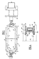
- the mold 1 for the continuous casting of steel has two large opposite plates 2 and two small opposite plates 3 which delimit between them a rectilinear cavity 4 in the direction of extraction of the slab and of cross section roughly rectangular.
- the plates 2 and 3 made of copper or a copper alloy, are fixed on steel reinforcing plates respectively 5 and 6 and are provided with grooves 7 provided for the passage of an appropriate cooling agent such as water. .
- the small plates 3 are supported on corresponding support faces 8 of the two large plates 2.
- the plates 2 and 3 are clamped against each other by clamping devices 10 which act on each small plate 3 via the corresponding reinforcement plates 6 in a direction roughly perpendicular to the faces d 'support 8.
- the angles of the cavity 4 are cut by chamfers 9.
- chamfers 9 are produced on the pair of small plates 3 and, as can be seen in FIG. 2, they are each formed by the hypotenuse "c" of a right triangle T whose sides "a" and “b” of the right angle have a length greater than 30mm and preferably between 30 and 150mm.
- the side “a” has a length equal to 80mm and the side “b” has a length equal to 50mm.
- each right triangle T is located in the plane of the internal wall of the large adjacent plate 2 and the side "b" is located in the plane of the internal wall of the small plate 3 on which the corresponding chamfer 9.
- the small plates 3 are connected to the large plates 2 by bearing faces 8 which are inclined towards the inside of the mold 1 at an angle of between 5 and 7 °.
- each longitudinal wall of the large plates 2 comprises, on the one hand, a draft 11 whose edge is also inclined towards the inside of the ingot mold at an angle of between 5 and 7 ° and, on the other hand, an extension 12 which forms, with said draft 11, an embedding by song at an angle for the small adjacent plate 3.
- the folding is all the more important as the thickness of the slab is high.
- FIGS. 3A to 3D The folding defects of the edges of the sheets obtained after rolling the slab were compared and shown in FIGS. 3A to 3D.
- Figs. 3A, 3B, 3C and 3D represent the images in section respectively at the level of the head, the middle, and the foot, of a bank of laminated sheet obtained after rolling slabs having chamfers of respective dimensions expressed in mm: 30 X 20; 50 X 65; 60 X 65; 80 X 50.
- a sheet made from a 300 mm thick slab without chamfer, not shown in the figures has a fold of about 40 mm with an average loss of material of 80 mm.
- the folding effect is no more than about 3 mm and does not disturb more than 15 mm of edge (3B and 3C).
- each small plate 30 of the mold 1 comprises, opposite the bearing faces 8, a shoe 31 which rests on the side face of the extension 12 of each large adjacent plate 2.
- the shoe 31 is long enough to take up the bending forces due to the withdrawal heat.
- each shoe 31 may include a zone 32 which is not in contact with the lateral face of the extension 12 and a thinned section 33 which creates a lever arm exerting an antagonistic force in the heat of withdrawal.
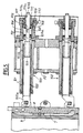
- FIG. 5 we will describe the clamping device 10.
- a clamping device which exerts a force on a small plate the clamping device exerting a force on the opposite small plate being identical.
- the clamping device 10 comprises two jacks 100 superimposed in a vertical plane.
- the jacks 100 of each group of jacks are joined together by a spacer 20.
- Each jack 100 comprises a cylinder 101 in which a hollow rod 102 is slidably mounted, one end 102a of which is integral with the reinforcement plate 6 of the corresponding small plate 3.
- an operating rod 103 which passes through a housing 104 fixed on the end of the cylinder 101.
- the operating rod 103 has a shoulder 103a which provides, with the housing 104 and the body of said operating rod 103, an internal chamber 105 closed by a piston 106 slidably mounted on the body of the rod 103 and inside the housing 104 .
- a cap 107 providing with the piston 106 a small internal chamber 108 into which opens a small pipe 109 which can be connected by a connector 110 to a pump not shown.
- the cap 107 has an internal threaded bore 107a into which a screw 111 is screwed.
- This screw 111 also has an internal bore 111a allowing the body of the rod 103 to pass through said screw.
- the end 111b of the screw 111 is in contact with the piston 106.
- the clamping operation of the plates 2 and 3 of the mold 1 is carried out as follows.
- the large plates 2 are tightened to come into contact effortlessly on the small plates 3, then the small plates 3 are tightened by action on the operating screw 103 which has a hexagon 103b for this purpose, so that the bearing faces 8 of the small plates 3 and of the large plates 2 come in contact.
- This operation is carried out by successive bearing between the operating rod 103 of the upper cylinder and the lower cylinder.
- the small chamber 108 is pressurized which has the effect of displacing the piston 106, compressing the elastic washers 112 and exerting a determined force on the small plate 3 by through the rod 102.
- the screw 111 is turned so that its end 111b comes into contact with the piston 106, which makes it possible to disconnect the pump.
- the elastic washers 112 hydraulically prestressed exert on the small plate 103 an almost constant force making it possible to resume the displacements due to dilations during casting.
- the ingot mold with plates according to the invention allows, thanks in particular to the dimensional characteristics of the chamfers of angle of the cavity, the total elimination of the defect of folding in edge of sheet and this without any incidence on the quality of the product obtained.
Landscapes
- Engineering & Computer Science (AREA)
- Mechanical Engineering (AREA)
- Continuous Casting (AREA)
Abstract
Description
La présente invention a pour objet une lingotière à plaques pour la coulée continue de métal, en particulier d'acier.The present invention relates to an ingot mold with plates for the continuous casting of metal, in particular steel.
Pour la coulée continue, notamment de brames d'acier, on utilise des lingotières comprenant quatre plaques refroidies qui délimitent entre elles une cavité pour la formation d'une brame coulée d'une section fixe déterminée. Cette cavité est rectiligne dans le sens de l'extraction de la brame et possède généralement une section transversale peu près rectangulaire.For continuous casting, in particular of steel slabs, molds are used comprising four cooled plates which delimit between them a cavity for the formation of a cast slab of a fixed fixed section. This cavity is rectilinear in the direction of the slab extraction and generally has a roughly rectangular cross section.
Les plaques formant deux parois opposées de la cavité de la lingotière sont appliquées contre des faces d'appui formées sur les autres plaques constituant les deux autres parois opposées de ladite cavité de la lingotière. Ces faces d'appui constituent en même temps des faces de joint entre les plaques, en ce sens qu'elles s'étendent jusqu'à la cavité de la lingotière et définissent ainsi des joints entre les faces internes des plaques.The plates forming two opposite walls of the mold cavity are applied against bearing faces formed on the other plates constituting the other two opposite walls of said mold cavity. These bearing faces constitute at the same time joint faces between the plates, in the sense that they extend to the cavity of the mold and thus define joints between the internal faces of the plates.
Les plaques de cette lingotière sont généralement serrées les unes contre les autres par des dispositifs de serrage agissant à peu près perpendiculairement aux faces d'appui.The plates of this mold are generally clamped against each other by clamping devices acting roughly perpendicular to the bearing faces.
Les brames coulées dans ce type de lingotière subissent ensuite un laminage pour l'obtention de tôles.The slabs cast in this type of ingot mold are then subjected to rolling to obtain sheets.
Or, au cours du laminage de certaines tôles, il se crée des repliures en rive de tôle mère qui, si elles sont trop profondes, subsistent après dérivage. Ce défaut provient d'un "écoulement" du coin supérieur de la brame sur le coin inférieur durent la mise à largeur.However, during the rolling of certain sheets, folds are created at the edge of the parent sheet which, if they are too deep, remain after drifting. This defect comes from a "flow" from the upper corner of the slab on the lower corner during the setting to width.
Par exemple, les tôles issues de brames épaisses d'environ 300mm subissent un fort corroyage travers car on transforme une brame d'environ 1700 mm de large en une tôle ayant une largeur de 4500 mm environ. Dans ce cas, pour éviter les repliures, il est indispensable de prévoir une réserve de métal, c'est à dire une largeur supplémentaire exceptionnelle d'environ 80mm. Cette largeur supplémentaire est une perte importante de matière.For example, sheets from slabs thick about 300mm undergo a strong cross-dressing because a slab of about 1700 mm wide is transformed into a sheet having a width of about 4500 mm. In this case, to avoid folds, it is essential to provide a metal reserve, that is to say an exceptional additional width of about 80mm. This additional width is a significant loss of material.
Une solution pour éviter ce défaut de repliure consiste par exemple à éliminer les coins de la brame en réalisant, au niveau de chaque coin un chanfrein par chalumeau.One solution to avoid this folding defect consists, for example, in eliminating the corners of the slab by making, at each corner, a chamfer by torch.
Mais, la confection des chanfreins par chalumeau est beaucoup trop onéreuse en perte de métal et en préparation.However, making the chamfers with a blowtorch is far too expensive in terms of metal loss and preparation.
Une autre solution consiste à couler directement des brames chanfreinées aux angles en utilisant des lingotières comprenant quatre plaques refroidies délimitant une cavité dont les angles sont coupés par des chanfreins comme dans le brevet US-A-3 237 252.Another solution consists in directly casting chamfered slabs at the angles using ingot molds comprising four cooled plates delimiting a cavity whose angles are cut by chamfers as in US-A-3,237,252.
Différents essais réalisés sur des brames chanfreinées montrent que le chanfrein doit posséder des caractéristiques dimensionnelles déterminées pour éviter totalement le défaut de repliure en rive de tôles.Various tests carried out on chamfered slabs show that the chamfer must have determined dimensional characteristics to completely avoid the defect in bending at the edge of sheets.
La présente invention a pour objet une lingotière à plaques pour la coulée continue de métal, selon le contenu de la revendication 1.The present invention relates to an ingot mold with plates for the continuous casting of metal, according to the content of claim 1.
Selon une caractéristique préférentielle de l'invention, les côtés de l'angle droit du triangle rectangle ont une longueur comprise entre 30 et 15mm, en fonction de la dimension des brames et de la nuance d'acier à couler.According to a preferred characteristic of the invention, the sides of the right angle of the right triangle have a length of between 30 and 15mm, depending on the size of the slabs and the grade of steel to be cast.
Selon d'autres caractéristiques de l'invention :
- les côtés de l'angle droit du triangle rectangle sont respectivement égaux à 80mm et 50mm pour des brames de 300mm d'épaisseur,
- les faces d'appui entre les plaques adjacentes sont inclinées vers l'intérieur de la lingotière selon un angle compris entre 5 et 7°,
- le chanfrein de chaque angle de la cavité est formé sur la paire de plaques constituant les petites parois de ladite cavité,
- les plaques constituant les petites parois de la cavité comportent à l'opposée de chaque face d'appui sur la plaque adjacente un patin s'appuyant sur une face latérale d'un prolongement de ladite plaque adjacente et assez long pour reprendre les efforts de flexion dûs aux chaudes de retrait,
- chaque patin comporte une zone s'écartant de la face latérale du prolongement de la plaque adjacente et une zone amincie exerçant un effort antagoniste aux chaudes de retrait.
- les dispositifs de serrage des plaques sont constitués par des vérins comportant des moyens de réglage de l'effort et de maintien du serrage,
- les moyens de réglage de l'effort et de maintien du serrage sont constitués par un empilement de rondelles élastiques précontraintes hydrauliquement.
- the sides of the right angle of the right triangle are respectively 80mm and 50mm for slabs 300mm thick,
- the bearing faces between the adjacent plates are inclined towards the inside of the mold at an angle of between 5 and 7 °,
- the chamfer of each angle of the cavity is formed on the pair of plates constituting the small walls of said cavity,
- the plates constituting the small walls of the cavity comprise, opposite each bearing face on the adjacent plate, a shoe bearing on a side face of an extension of said adjacent plate and long enough to take up the bending forces due to shrinkage hot,
- each skate has a deviating area of the lateral face of the extension of the adjacent plate and a thinned zone exerting an antagonistic force to the heat of withdrawal.
- the plate clamping devices are constituted by jacks comprising means for adjusting the force and maintaining the clamping,
- the means for adjusting the force and for maintaining the tightening consist of a stack of hydraulically prestressed elastic washers.
D'autres caractéristiques et avantages de la présente invention apparaitront au cours de la description qui va suivre, faite en rérérence aux dessins annexés sur lesquels :
- la Fig. 1 est une vue en plan schématique d'une lingotière à plaques selon l'invention,
- la Fig. 2 est une vue en plan schématique à plus grande échelle et en demi-coupe d'une petite plaque de la lingotière,
- les Figs. 3A à 3D représentent les images en coupe, d'une rive de tôles laminées après laminage de brames
- la Fig. 4 est une vue en plan schématique d'une variante de la petite plaque de la lingotière,
- la Fig. 5 est une vue en coupe à plus grande échelle d'un dispositif de serrage des plaques des petites faces de la lingotière.
- Fig. 1 is a schematic plan view of an ingot mold with plates according to the invention,
- Fig. 2 is a schematic plan view on a larger scale and in half-section of a small plate of the mold,
- Figs. 3A to 3D represent the sectional images of a bank of rolled sheets after rolling slabs
- Fig. 4 is a schematic plan view of a variant of the small plate of the mold,
- Fig. 5 is an enlarged sectional view of a device for clamping the plates of the small faces of the mold.
En se reportant tout d'abord aux Figs. 1 et 2, on voit que la lingotière 1 pour la coulée continue d'acier comporte deux grandes plaques opposées 2 et deux petites plaques opposées 3 qui délimitent entre elles une cavité 4 rectiligne dans le sens d'extraction de la brame et de section transversale à peu près rectangulaire.Referring first to Figs. 1 and 2, it can be seen that the mold 1 for the continuous casting of steel has two large
Les plaques 2 et 3, en cuivre ou en alliage de cuivre, sont fixées sur des plaques de renfort en acier respectivement 5 et 6 et sont munies de rainures 7 prévues pour le passage d'un agent de refroidissement approprié telle que de l'eau.The
Les petites plaques 3 s'appuient sur des faces d'appui 8 correspondantes des deux grandes plaques 2.The
D'autre part, les plaques 2 et 3 sont serrées les unes contre les autres par des dispositifs de serrage 10 qui agissent sur chaque petite plaque 3 par l'intermédiaire des plaques de renfort correspondante 6 selon une direction à peu près perpendiculaire aux faces d'appui 8.On the other hand, the
Les angles de la cavité 4 sont coupés par des chanfreins 9.The angles of the
Ces chanfreins 9 sont réalisés sur la paire de petites plaques 3 et, comme on peut le voir sur la Fig. 2, ils sont chacun formés par l'hypoténuse "c" d'un triangle rectangle T dont les côtés "a" et "b" de l'angle droit ont une longueur supérieure à 30mm et de préférence comprise entre 30 et 150mm.These
Dans l'exemple représenté, le côté "a" a une longueur égale à 80mm et le côté "b" a une longueur égale à 50mm.In the example shown, the side "a" has a length equal to 80mm and the side "b" has a length equal to 50mm.
Le côté "a" de chaque triangle rectangle T est situé dans le plan de la paroi interne de la grande plaque adjacente 2 et le côté "b" est situé dans le plan de la paroi interne de la petite plaque 3 sur laquelle est formé le chanfrein 9 correspondant.The side "a" of each right triangle T is located in the plane of the internal wall of the large
Les petites plaques 3 se raccordent aux grandes plaques 2 par des faces d'appui 8 qui sont inclinées vers l'intérieur de la lingotière 1 selon un angle compris entre 5 et 7°.The
A cet effet, chaque paroi longitudinale des grandes plaques 2 comporte, d'une part, une dépouille 11 dont le chant est également incliné vers l'intérieur de la lingotière selon un angle compris entre 5 et 7° et, d'autre part, un prolongement 12 qui forme, avec ladite dépouille 11, un encastrement par chant en biais pour la petite plaque 3 adjacente.To this end, each longitudinal wall of the
Cet encastrement permet d'améliorer sensiblement l'étanchéité entre les plaques 2 et 3 de la lingotière.This embedding significantly improves the seal between the
Lors du laminage, on a constaté que le défaut de repliures est provoqué par un écoulement du coin supérieur de la brame sur le coin inférieur et cela durant la mise en longueur.During rolling, it was found that the defect in folds is caused by a flow from the upper corner of the slab to the lower corner and this during the lengthening.
La repliure est d'autant plus importante que l'épaisseur de la brame est élevée.The folding is all the more important as the thickness of the slab is high.
Différentes brames d'environ 300 mm d'épaisseur ont été coulées, chacune ayant des chanfreins de dimensions déterminées.Different slabs about 300 mm thick were poured, each with chamfers of determined dimensions.
Les défauts de repliures des rives des tôles obtenues après laminage de la brame, ont été comparés et représentés sur les Figs. 3A à 3D.The folding defects of the edges of the sheets obtained after rolling the slab were compared and shown in FIGS. 3A to 3D.
Les Figs. 3A, 3B, 3C et 3D représentent les images en couper respectivement au niveau de la tête, du milieu, et du pied, d'une rive de tôle laminée obtenue après laminage de brames ayant des chanfreins de dimensions respectives exprimées en mm : 30 X 20 ; 50 X 65 ; 60 X 65 ; 80 X 50.Figs. 3A, 3B, 3C and 3D represent the images in section respectively at the level of the head, the middle, and the foot, of a bank of laminated sheet obtained after rolling slabs having chamfers of respective dimensions expressed in mm: 30
Une tôle réalisée à partir d'une brame de 300 mm d'épaisseur sans chanfrein, non représenté sur les figures présente une repliure d'environ 40 mm avec une perte de matière moyenne de 80 mm.A sheet made from a 300 mm thick slab without chamfer, not shown in the figures has a fold of about 40 mm with an average loss of material of 80 mm.
Lorsque le chanfrein correspond à triangle rectangle dont les côtés de l'angle droit a X b sont respectivement égaux à 30 X 20mm, la repliure est de 10 mm, mais ne perturbe que 30 mm de rive (Fig. 3A).When the chamfer corresponds to a right triangle whose sides of the right angle a X b are respectively equal to 30 X 20mm, the fold is 10 mm, but only disturbs 30 mm of edge (Fig. 3A).
Lorsque le chanfrein correspond à un triangle rectangle dont les côtés de l'angle droit a X b sont, en dimension, supérieures à 30 mm, on remarque que l'effet de repliure n'est plus que d'environ 3 mm et ne perturbe plus que 15 mm de rive (3B et 3C).When the chamfer corresponds to a right triangle whose sides of the right angle a X b are, in dimension, greater than 30 mm, we notice that the folding effect is no more than about 3 mm and does not disturb more than 15 mm of edge (3B and 3C).
Selon une forme préférentielle, lorsque le chanfrein correspond à un triangle rectangle dont les côtés de l'angle droit a X b ont respectivement pour dimension 80 X 50 mm, on constater de manière remarquable, la disparition totale de la repliure (Fig. 3D).According to a preferred form, when the chamfer corresponds to a right triangle whose sides of the right angle a X b have respectively the dimension 80 X 50 mm, we remark remarkably, the total disappearance of the fold (Fig. 3D) .
Selon une variante représentée sur la Fig.4, chaque petite plaque 30 de le lingotière 1 comporte, à l'opposé des faces d'appui 8, un patin 31 qui s'appuie sur la face latérale du prolongement 12 de chaque grande plaque adjacente 2. Le patin 31 est assez long pour reprendre les efforts de flexion dûs aux chaudes de retrait.According to a variant shown in Fig.4, each
Par ailleurs, chaque patin 31 peut comporter une zone 32 qui n'est pas en contact avec la face latérale du prolongement 12 et une section amincie 33 qui crée un bras de levier exercant un effort antagoniste aux chaudes de retrait.Furthermore, each
En se reportant maintenant à la Fig. 5, on va décrire le dispositif de serrage 10. Sur cette figure, on a représenté un dispositif de serrage qui exerce un effort sur une petite plaque le dispositif de serrage exerçant un effort sur la petite plaque opposée étant identique.Referring now to FIG. 5, we will describe the
Le dispositif de serrage 10 comporte deux vérins 100 superposés dans un plan vertical.The clamping
Les vérins 100 de chaque groupe de vérin sont solidarisés entre eux par une entretoise 20.The
Chaque vérin 100 comporte un cylindre 101 dans lequel est montée coulissant une tige creuse 102 dont une extrémité 102a est solidaire de la plaque de renfort 6 de la petite plaque correspondante 3.Each
Dans l'autre extrémité 102b de la tige creuse 102 est vissée une tige de manoeuvre 103 qui traverse un boîtier 104 fixé sur l'extrémité du cylindre 101.In the
La tige de manoeuvre 103 comporte un épaulement 103a qui ménage avec le boîtier 104 et le corps de ladite tige de manoeuvre 103 une chambre interne 105 fermée par un piston 106 monté coulissant sur le corps de la tige 103 et à l'intérieur du boîtier 104.The operating
A l'extrémité du boîtier 104 est fixé un capuchon 107 ménageant avec le piston 106 une petite chambre interne 108 dans laquelle débouche une petite canalisation 109 qui peut être reliée par un raccord 110 à une pompe non représentée.At the end of the housing 104 is fixed a
Le capuchon 107 comporte un alésage interne fileté 107a dans lequel une vis 111 est vissée. Cette vis 111 comporte également un alésage interne 111a permettant au corps de la tige 103 de traverser ladite vis. L'extrémtié 111b de la vis 111 est en contact avec le piston 106.The
Dans la chambre 105, entre l'épaulement 103a et le piston 106, est monté, sur le corps de le tige 103, un empilement de rondelles élastiques 112.In the
L'opération de serrage des plaques 2 et 3 de la lingotière 1 s'effectue de la manière suivante.The clamping operation of the
Tout d'abord, on effectue le serrage des grandes plaques 2 pour venir en contact sans effort sur les petites plaques 3, puis on effectue le serrage des petites plaques 3 par action sur la vis de manoeuvre 103 qui comporte à cet effet un six pans 103b, afin que les faces d'appui 8 des petites plaques 3 et des grandes plaques 2 viennent en contact.First of all, the
Cette opération est réalisée par palier successif entre la tige de manoeuvre 103 du vérin supérieur et du vérin inférieur.This operation is carried out by successive bearing between the operating
Ensuite, après avoir branché une pompe sur le raccordement 110, on met en pression la petite chambre 108 ce qui a pour effet de déplacer le piston 106, de comprimer les rondelles élastiques 112 et d'exercer un effort déterminé sur la petite plaque 3 par l'intermédiaire de la tige 102.Then, after having connected a pump to the
Pour maintenir cet effort constant, on tourne la vis 111 pour que son extrémité 111b vienne en contact avec le piston 106, ce qui permet de débrancher la pompe.To maintain this constant force, the
Ainsi, les rondelles élastiques 112 précontraintes hydrauliquement exercent sur la petite plaque 103 un effort quasi constant permettant de reprendre les déplacements dûs aux dilatations en cours de coulée.Thus, the
La lingotière à plaques selon l'invention permet, grâce notamment aux caractéristiques dimensionnelles des chanfreins d'angle de la cavité, l'élimination totale du défaut de repliure en rive de tôle et cela sans aucune incidence sur la qualité du produit obtenu.The ingot mold with plates according to the invention allows, thanks in particular to the dimensional characteristics of the chamfers of angle of the cavity, the total elimination of the defect of folding in edge of sheet and this without any incidence on the quality of the product obtained.
Claims (8)
- Plate ingot mould for the continuous casting of metal, in particular of slabs, comprising four cooled plates (2, 3 - 30) delimiting between them a cavity (4) which has a substantially rectangular cross-section and of which the corners are cut by chamfers (9), the said plates comprising two large opposing plates (2) forming the large walls of the cavity, and two small opposing plates (3 - 30) forming the small walls of the said cavity and resting on corresponding bearing surfaces of the large plates (2), the plates (2, 3 - 30) being intended to be tightened against one another by tightening devices (10) acting substantially perpendicularly to the bearing faces (8), characterised in that the chamfer (9) of each corner of the cavity (4) is formed by the hypotenuse of a right-angled triangle, and the sides of the said triangle forming the right angle comprise a large and small side of a length greater than 30 mm, the large side of the each right-angled triangle being situated in the plane of each large wall of the cavity (4) and the small side of each right-angled triangle being situated in the plane of each small wall of the said cavity (4), and that the bearing faces (8) between the adjacent plates (2, 3 - 30) are inclined towards the interior of the ingot mould (1) at an angle between 5 and 7°.
- Plate ingot mould according to Claim 1, characterised in that the sides forming the right angle of the right-angled triangle have a length between 30 and 150 mm.
- Plate ingot mould according to Claims 1 and 2, characterised in that the sides forming the right angle of the right-angled triangle are equal respectively to 80 mm and 50 mm for slabs having thickness of 300 mm.
- Plate ingot mould according to one of Claims 1 to 3, characterised in that the chamfer (9) of each corner of the cavity (4) is formed on the pair of plates (3 - 30) forming the small walls of the cavity (4).
- Plate ingot mould according to one of Claims 1 to 4, characterised in that the plates (30) forming the small walls of the cavity (4) comprise, on the opposite side from each bearing face (8) on the adjacent plate (2), a block (31) which bears on a lateral face of an extension <12) of said adjacent plate (2) and is long enough to take up the bending stresses caused by heat shrinkage.
- Plate ingot mould according to Claim 5, characterised in that each block (31) comprises a zone (32) spaced from the lateral face of the extension (12) of the adjacent plate (2) and a thinned-down section (33) exerting a force antagonistic to the heat shrinkage.
- Plate ingot mould according to Claim 1, in which the devices (10) for tightening the plates (2, 3 - 30) consist of jacks (100), characterised in that each jack (100) comprises means for adjusting the force and for maintaining the tightening.
- Plate ingot mould according to Claim 7, characterised in that the means for adjusting the force and for maintaining the tightening consist of a stack of hydraulically prestressed elastic washers (112).
Priority Applications (1)
| Application Number | Priority Date | Filing Date | Title |
|---|---|---|---|
| AT90402033T ATE96705T1 (en) | 1989-07-19 | 1990-07-13 | PLATE MOLD FOR CONTINUOUS METAL CASTING. |
Applications Claiming Priority (2)
| Application Number | Priority Date | Filing Date | Title |
|---|---|---|---|
| FR8909731 | 1989-07-19 | ||
| FR898909731A FR2649918B1 (en) | 1989-07-19 | 1989-07-19 | PLATE LINGOTIERE FOR CONTINUOUS CASTING OF METAL |
Publications (2)
| Publication Number | Publication Date |
|---|---|
| EP0409708A1 EP0409708A1 (en) | 1991-01-23 |
| EP0409708B1 true EP0409708B1 (en) | 1993-11-03 |
Family
ID=9383935
Family Applications (1)
| Application Number | Title | Priority Date | Filing Date |
|---|---|---|---|
| EP90402033A Expired - Lifetime EP0409708B1 (en) | 1989-07-19 | 1990-07-13 | Plate mould for continuous casting of metal |
Country Status (7)
| Country | Link |
|---|---|
| US (1) | US5191924A (en) |
| EP (1) | EP0409708B1 (en) |
| JP (1) | JP3001063B2 (en) |
| AT (1) | ATE96705T1 (en) |
| DE (1) | DE69004367T2 (en) |
| ES (1) | ES2048459T3 (en) |
| FR (1) | FR2649918B1 (en) |
Families Citing this family (10)
| Publication number | Priority date | Publication date | Assignee | Title |
|---|---|---|---|---|
| CN2776595Y (en) * | 2005-03-07 | 2006-05-03 | 鞍钢集团新钢铁有限责任公司 | Profile crystallizer for plate blank continuous casting |
| CN1840252A (en) * | 2005-03-28 | 2006-10-04 | 鞍钢集团新钢铁有限责任公司 | Production process of continuous-casting tandem-rolling coiled sheet of medium thick plate |
| RU2323062C1 (en) * | 2006-07-04 | 2008-04-27 | ООО "Корад" | Slab continuous casting mold |
| RU2340425C2 (en) * | 2006-09-25 | 2008-12-10 | Открытое акционерное общество "Магнитогорский металлургический комбинат" | Mold for steel continuous casting |
| DE102007054911B4 (en) * | 2007-11-15 | 2015-02-05 | Thyssenkrupp Steel Europe Ag | Width-adjustable mold and method for producing a hot strip |
| US20110308760A1 (en) * | 2009-02-09 | 2011-12-22 | Hisamune Tanaka | Apparatus for production of metallic slab using electron beam, and process for production of metallic slab using the apparatus |
| KR101360564B1 (en) | 2011-12-27 | 2014-02-24 | 주식회사 포스코 | Mold in continuous casting |
| DE102012108952A1 (en) | 2012-09-21 | 2014-05-15 | Voestalpine Stahl Gmbh | Apparatus for continuous casting of metals |
| JP6085571B2 (en) * | 2014-01-06 | 2017-02-22 | 三島光産株式会社 | Continuous casting mold |
| CN110405163B (en) * | 2019-09-03 | 2023-05-23 | 山东钢铁股份有限公司 | Equipment and method for eliminating black line defect at edge of rolled material of large-width steel plate |
Family Cites Families (11)
| Publication number | Priority date | Publication date | Assignee | Title |
|---|---|---|---|---|
| US3237252A (en) * | 1963-10-01 | 1966-03-01 | Babcock & Wilcox Co | Mold clamping devices |
| CH577863A5 (en) * | 1974-11-04 | 1976-07-30 | Concast Ag | |
| FR2436636A1 (en) * | 1978-09-21 | 1980-04-18 | Fives Cail Babcock | Clamping device for walls of continuous casting mould - where stack of cup springs initially compressed via hydraulic cylinder apply clamping pressure |
| SU850280A1 (en) * | 1979-04-04 | 1981-08-03 | Центральный Ордена Трудового Красногознамени Научно-Исследовательский Ин-Ститут Черной Металлургии Им.И.П.Бардина | Mould for continuous casting plants |
| SU923727A1 (en) * | 1979-06-22 | 1982-04-30 | Sergej P Bakumenko | CRYSTALIZER FOR FORMING INGOT I |
| LU81982A1 (en) * | 1979-12-11 | 1981-07-23 | Arbed | CONTINUOUS CASTING MILLS SUITABLE FOR CURVING STEEL MULTIPLE STEEL PROFILES AND METHOD FOR THE FINISHING OF THEIR INTERIOR SURFACES |
| JPS5731444A (en) * | 1980-07-31 | 1982-02-19 | Mitsubishi Heavy Ind Ltd | Mold for continuous casting machine |
| JPS5747557A (en) * | 1980-09-06 | 1982-03-18 | Daido Steel Co Ltd | Mold for continuous casting |
| CH664915A5 (en) * | 1984-10-26 | 1988-04-15 | Concast Service Union Ag | CONTINUOUS CHOCOLATE FOR CONTINUOUSLY STEEL STRIPS WITH POLYGONAL CROSS-SECTION. |
| FR2584322B1 (en) * | 1985-07-04 | 1987-12-31 | Fives Cail Babcock | DEVICE FOR ASSEMBLING THE DIMENSIONS OF A CONTINUOUS CASTING LINGOTIERE |
| US4947925A (en) * | 1989-02-24 | 1990-08-14 | Wagstaff Engineering, Inc. | Means and technique for forming the cavity of an open-ended mold |
-
1989
- 1989-07-19 FR FR898909731A patent/FR2649918B1/en not_active Expired - Fee Related
-
1990
- 1990-07-13 ES ES90402033T patent/ES2048459T3/en not_active Expired - Lifetime
- 1990-07-13 EP EP90402033A patent/EP0409708B1/en not_active Expired - Lifetime
- 1990-07-13 DE DE90402033T patent/DE69004367T2/en not_active Expired - Lifetime
- 1990-07-13 AT AT90402033T patent/ATE96705T1/en not_active IP Right Cessation
- 1990-07-18 US US07/554,704 patent/US5191924A/en not_active Expired - Lifetime
- 1990-07-19 JP JP2191846A patent/JP3001063B2/en not_active Expired - Lifetime
Also Published As
| Publication number | Publication date |
|---|---|
| FR2649918A1 (en) | 1991-01-25 |
| DE69004367D1 (en) | 1993-12-09 |
| DE69004367T2 (en) | 1994-04-28 |
| JP3001063B2 (en) | 2000-01-17 |
| US5191924A (en) | 1993-03-09 |
| ES2048459T3 (en) | 1994-03-16 |
| JPH0381048A (en) | 1991-04-05 |
| ATE96705T1 (en) | 1993-11-15 |
| EP0409708A1 (en) | 1991-01-23 |
| FR2649918B1 (en) | 1994-06-10 |
Similar Documents
| Publication | Publication Date | Title |
|---|---|---|
| EP0409708B1 (en) | Plate mould for continuous casting of metal | |
| CA2122333C (en) | Butt positioning and welding assembly using a laser jet for steel sheets welding | |
| CA1322668C (en) | Concrete wood floor | |
| FR2467645A1 (en) | BENDING TOOL | |
| CH644288A5 (en) | METHOD AND MACHINE FOR CONTINUOUS CASTING OF METAL. | |
| EP0707902B1 (en) | Rolling installation | |
| EP2480729A1 (en) | Metal profile member to be used as a formwork assisting in the construction of metal/concrete flooring | |
| EP0226477B1 (en) | Screw cutter | |
| FR2627405A1 (en) | PROCESS FOR WIREDING METAL, ESPECIALLY ALUMINUM, AND WELDING PRESS FOR IMPLEMENTING THE METHOD | |
| FR2800654A1 (en) | LINGOTIERE WITH WIDE SECTION FOR VERTICAL CONTINUOUS CASTING IN METAL LOAD | |
| EP0379407B1 (en) | Pressure casting mould for flat metallic products such as slabs | |
| FR2649340A1 (en) | METHOD AND DEVICE FOR CONTINUOUS CASTING BETWEEN CYLINDERS OF THIN METAL PRODUCTS FOR DIRECT COLD ROLLING | |
| FR2759106A1 (en) | Concrete cavity wall construction procedure | |
| EP1910211B1 (en) | Guidance device for masts sliding one within the other telescopic arms and guidance method | |
| FR2646151A1 (en) | TIGHTENING BLOCK WITH SELF-TIGHTENING JAWS, ESPECIALLY FOR A LINEAR HYDRAULIC WINCH | |
| EP0738546A1 (en) | Rolling mill with large opening | |
| FR2652020A1 (en) | Method and device for reducing the thickness of a continuously cast slab | |
| FR2729879A1 (en) | METHOD AND APPARATUS FOR SPOT WELDING FOR THE ASSEMBLY OF A BEAM BOX OF A CRANE | |
| FR2522547A1 (en) | METHOD AND DEVICE FOR CONTROLLING THE WIDTH AND THICKNESS OF A STRIP | |
| FR2613747A1 (en) | Crosspiece with movable and orientable bearing points for forming shuttering panels, and shuttering panels made by means of this crosspiece | |
| EP0074292B1 (en) | Apparatus for machining ingot moulds | |
| FR2650966A1 (en) | METHOD AND DEVICE FOR DIRECT CONTINUOUS CASTING THIN METAL PRODUCTS | |
| FR2670142A1 (en) | METHOD AND DEVICE FOR CONTINUOUS CASTING A METAL THIN STRIP AND SIDE SHUTTER PLATE OF SUCH CONTINUOUS CASTING DEVICE | |
| FR2562117A1 (en) | Method and device for establishing continuity between two concrete beams | |
| EP1597002B1 (en) | Ingot mould for quenching metals and ingots thus obtained |
Legal Events
| Date | Code | Title | Description |
|---|---|---|---|
| PUAI | Public reference made under article 153(3) epc to a published international application that has entered the european phase |
Free format text: ORIGINAL CODE: 0009012 |
|
| AK | Designated contracting states |
Kind code of ref document: A1 Designated state(s): AT BE CH DE DK ES FR GB GR IT LI LU NL SE |
|
| 17P | Request for examination filed |
Effective date: 19901205 |
|
| 17Q | First examination report despatched |
Effective date: 19920324 |
|
| GRAA | (expected) grant |
Free format text: ORIGINAL CODE: 0009210 |
|
| AK | Designated contracting states |
Kind code of ref document: B1 Designated state(s): AT BE CH DE DK ES FR GB GR IT LI LU NL SE |
|
| PG25 | Lapsed in a contracting state [announced via postgrant information from national office to epo] |
Ref country code: IT Free format text: LAPSE BECAUSE OF FAILURE TO SUBMIT A TRANSLATION OF THE DESCRIPTION OR TO PAY THE FEE WITHIN THE PRESCRIBED TIME-LIMIT;WARNING: LAPSES OF ITALIAN PATENTS WITH EFFECTIVE DATE BEFORE 2007 MAY HAVE OCCURRED AT ANY TIME BEFORE 2007. THE CORRECT EFFECTIVE DATE MAY BE DIFFERENT FROM THE ONE RECORDED. Effective date: 19931103 Ref country code: DK Effective date: 19931103 Ref country code: GR Free format text: LAPSE BECAUSE OF FAILURE TO SUBMIT A TRANSLATION OF THE DESCRIPTION OR TO PAY THE FEE WITHIN THE PRESCRIBED TIME-LIMIT Effective date: 19931103 Ref country code: SE Effective date: 19931103 |
|
| REF | Corresponds to: |
Ref document number: 96705 Country of ref document: AT Date of ref document: 19931115 Kind code of ref document: T |
|
| REF | Corresponds to: |
Ref document number: 69004367 Country of ref document: DE Date of ref document: 19931209 |
|
| GBT | Gb: translation of ep patent filed (gb section 77(6)(a)/1977) |
Effective date: 19940216 |
|
| REG | Reference to a national code |
Ref country code: ES Ref legal event code: FG2A Ref document number: 2048459 Country of ref document: ES Kind code of ref document: T3 |
|
| EPTA | Lu: last paid annual fee | ||
| PLBE | No opposition filed within time limit |
Free format text: ORIGINAL CODE: 0009261 |
|
| STAA | Information on the status of an ep patent application or granted ep patent |
Free format text: STATUS: NO OPPOSITION FILED WITHIN TIME LIMIT |
|
| 26N | No opposition filed | ||
| REG | Reference to a national code |
Ref country code: GB Ref legal event code: IF02 |
|
| PGFP | Annual fee paid to national office [announced via postgrant information from national office to epo] |
Ref country code: ES Payment date: 20090812 Year of fee payment: 20 Ref country code: FR Payment date: 20090710 Year of fee payment: 20 |
|
| PGFP | Annual fee paid to national office [announced via postgrant information from national office to epo] |
Ref country code: AT Payment date: 20090715 Year of fee payment: 20 Ref country code: CH Payment date: 20090721 Year of fee payment: 20 Ref country code: DE Payment date: 20090709 Year of fee payment: 20 Ref country code: NL Payment date: 20090705 Year of fee payment: 20 Ref country code: GB Payment date: 20090708 Year of fee payment: 20 Ref country code: LU Payment date: 20090804 Year of fee payment: 20 |
|
| PGFP | Annual fee paid to national office [announced via postgrant information from national office to epo] |
Ref country code: BE Payment date: 20090805 Year of fee payment: 20 |
|
| REG | Reference to a national code |
Ref country code: NL Ref legal event code: V4 Effective date: 20100713 |
|
| REG | Reference to a national code |
Ref country code: CH Ref legal event code: PL |
|
| BE20 | Be: patent expired |
Owner name: *CLECIM Effective date: 20100713 Owner name: *SOLLAC Effective date: 20100713 |
|
| REG | Reference to a national code |
Ref country code: GB Ref legal event code: PE20 Expiry date: 20100712 |
|
| REG | Reference to a national code |
Ref country code: ES Ref legal event code: FD2A Effective date: 20100714 |
|
| PG25 | Lapsed in a contracting state [announced via postgrant information from national office to epo] |
Ref country code: NL Free format text: LAPSE BECAUSE OF EXPIRATION OF PROTECTION Effective date: 20100713 Ref country code: ES Free format text: LAPSE BECAUSE OF EXPIRATION OF PROTECTION Effective date: 20100714 |
|
| PG25 | Lapsed in a contracting state [announced via postgrant information from national office to epo] |
Ref country code: GB Free format text: LAPSE BECAUSE OF EXPIRATION OF PROTECTION Effective date: 20100712 |
|
| PG25 | Lapsed in a contracting state [announced via postgrant information from national office to epo] |
Ref country code: DE Free format text: LAPSE BECAUSE OF EXPIRATION OF PROTECTION Effective date: 20100713 |