EP0409266B1 - Branddetektor - Google Patents
Branddetektor Download PDFInfo
- Publication number
- EP0409266B1 EP0409266B1 EP90113961A EP90113961A EP0409266B1 EP 0409266 B1 EP0409266 B1 EP 0409266B1 EP 90113961 A EP90113961 A EP 90113961A EP 90113961 A EP90113961 A EP 90113961A EP 0409266 B1 EP0409266 B1 EP 0409266B1
- Authority
- EP
- European Patent Office
- Prior art keywords
- radiation
- thermocouple
- fire detector
- fire
- test
- Prior art date
- Legal status (The legal status is an assumption and is not a legal conclusion. Google has not performed a legal analysis and makes no representation as to the accuracy of the status listed.)
- Expired - Lifetime
Links
Images

Classifications
-
- G—PHYSICS
- G08—SIGNALLING
- G08B—SIGNALLING SYSTEMS, e.g. PERSONAL CALLING SYSTEMS; ORDER TELEGRAPHS; ALARM SYSTEMS
- G08B17/00—Fire alarms; Alarms responsive to explosion
- G08B17/12—Actuation by presence of radiation or particles, e.g. of infrared radiation or of ions
Definitions
- the invention relates to a fire detector according to the preamble of claim 1.
- a fire detector is described in DE 25 12 650 C2, which has a sensor element that detects the radiation emitted by a flame. The spectral composition of the radiation is analyzed and an alarm signal is generated depending on the result. Semiconductor components such as photodiodes or photo elements are used as the sensor element. These have the disadvantage that their interference signal spacing, ie the ratio of the useful signal to the interference signal, decreases sharply with increasing ambient temperature, since at high temperatures their interference signal is high, for example as a result of thermal noise, and their sensitivity decreases. The ambient temperature can vary widely when operating fire detectors Fluctuate range.
- Typical operating temperatures of fire detectors range, for example, from -40 ° C to + 60 ° and higher in the event of a fire, at which the fire detector should still work properly.
- the response threshold of the useful signal ie the signal that can trigger an alarm, must be greater than the maximum interference signal.
- thermocouple A fire detector is known from US Pat. No. 2,834,008, the sensor element of which is designed as a thermocouple.
- the AC voltage signal emitted by the thermocouple is evaluated within a predetermined frequency range.
- an evaluation unit If the signal amplitudes typical for a fire occur in the range from 3 to 30 Hz, an evaluation unit generates an alarm signal.
- thermocouples for temperature measurement.
- the voltage generated by a thermocouple depends on the temperature difference between the measuring point and the reference point.
- the reference junction temperature must be kept at a known temperature that is as constant as possible.
- the thermocouple generates a voltage depending on the temperature difference between its measuring point and its reference point.
- the reference junction is connected to a heat sink, which assumes the temperature of the room as a result of heat conduction. Since the heat sink stores heat, short-term temperature fluctuations of the room follow only slowly, so that a temperature is established over time on the heat sink which corresponds approximately to the mean temperature of the room.
- the measuring point of the thermocouple has a small heat capacity and can Follow temperature changes quickly. Accordingly, the temperature of the measuring point of the thermocouple is influenced by absorption of radiation energy, which emits a heat source, and / or by heating due to heat conduction, for example by thermal convection. In the event of a fire, both types of heat transfer are effective, ie the thermocouple detects parts of both forms of energy. This increases the sensitivity of the fire detector to the known device.
- thermocouple emits a signal that is proportional to the temperature difference between the reference point and the measuring point, regardless of the absolute temperature.
- the absolute temperature of the room does not affect the sensitivity of the fire detector.
- the interference signal from thermocouples is small over a wide temperature range, since their thermal noise is smaller than that from semiconductor components.
- the fire detector therefore has an almost constant signal-to-noise ratio over its entire operating temperature range. This makes it possible to select the response threshold for detecting a fire accordingly low, so that fires can be detected early. Since, unlike in the prior art, no semiconductor component is used as the sensor element, which is known to have a low limit temperature, the temperature range in which the fire detector can be used is also enlarged compared to the prior art. The consequence of this is that the fire detector remains functional even at high temperatures, for example in the event of a fire, and can provide information about the course of the fire.
- thermocouples are connected together to form a thermopile. This measure increases the sensitivity of the fire detector even further.
- thermocouple is preceded by an optical filter which is transparent to radiation of a wavelength specific to the fire.
- the flames emit radiation with a characteristic wavelength that differs from the wavelength of other heat sources.
- the measures mentioned effectively suppress interference radiation from heat sources, such as incandescent lamps, radiators, etc.
- the alarm signal can be generated depending on the exceeding of a predetermined threshold value of the signal of the thermocouple and / or depending on the flicker frequency of the signal.
- the frequency of the radiation emanating from a fire can also be used to distinguish the radiation emanating from a fire from interference radiation.
- the frequency at which a flame emits radiation is normally in a frequency range from 0.5 to 10 Hz. If the evaluation of the signals from the thermocouple is limited to this frequency range, the interference signal from the interference radiation of other heat sources with deviating frequencies can , such as ambient light with a frequency of 0 Hz or radiation from an incandescent lamp with a frequency of 100 Hz, do not distort the result.
- the response of the fire detector to fires becomes even more selective and therefore more reliable.
- thermocouple which can receive test radiation and which emits a test signal to the evaluation unit which, depending on its size, generates a state signal indicating the functional state of the fire detector, and that A protective glass is connected upstream of the thermocouple and the test sensor, which is broadband transparent to radiation.
- Fire detectors which among other things also evaluate the radiation for fire detection, are naturally sensitive to contamination, since the radiation is already absorbed by dirt particles before they reach the radiation-sensitive surface of the sensor element. This reduces the sensitivity of the fire detector and, at a certain degree of contamination, the fire detector can no longer function properly. This is also critical because the other electrical functions of the fire detector still work properly when contaminated, so that an electrical test cannot provide any information about the functionality of the band detector.
- at least two sensor elements namely the thermocouple and the test sensor, are preceded by a protective glass. This is exposed to the ambient air and can become dirty. The permeability of the protective glass for broadband radiation is determined with the help of the test sensor.
- thermocouple Its spectral sensitive speed can be in a different wavelength range than the radiation detected by the thermocouple, since it can be assumed that the dirt on the protective glass generally attenuates the incident radiation over a broad band.
- the fire detector is functional both with regard to its electrical function and with regard to its ability to detect radiation from a fire.
- the aforementioned embodiment of the invention can be developed in a sensible manner such that the test radiation is modulated and a demodulator module is provided in the evaluation unit for demodulating the test signal. It is thereby achieved that the signal which is caused by the test radiation differs significantly from the signal of the radiation from other radiation sources.
- the test signal thus has a high signal-to-noise ratio, so that the degree of contamination of the protective glass can be determined with high reliability.
- thermopile 16 arranged in the upper circuit branch in FIG. 1 receives radiation 10 through an optical radiation-transmissive cover 12, from which an interference filter 14 passes a wavelength range characteristic of a fire.
- the thermopile 16 has a reference junction which is connected to a heat sink 18. This consists of a heat-storing material, such as ceramic, and is exposed to the ambient temperature of the room. The heat storage causes short-term temperature fluctuations in the room to be averaged out, so that an average temperature Tm is established on the heat sink 18.
- the measuring point of the thermopile 16 is supplied with the radiation transmitted by the interference filter 14, which heats it. Furthermore, a heat flow 20 with the temperature Tw can also act on the measuring point. This heat flow 20 can arise, for example, as a result of heat convection in the event of a fire and is therefore used in addition to the radiation 10 for fire detection. A temperature T1 thus arises at the measuring point of the thermopile 16, which has arisen from different energy transfer, namely through thermal convection and thermal radiation.
- the measuring point has a smaller heat capacity than the reference point thermally connected to the heat sink 18, so that it can follow short-term fluctuations in the radiation 10 and / or the heat flow 20.
- the temperature difference between the measuring point and the reference point of the thermopile 16 generates after Seebeck effect an electrical voltage, which is amplified by a matching amplifier 22, the impedance of which is matched to the internal resistance of the thermopile 16.
- the output signal of the adaptation amplifier 22 is fed to an amplifier 24, a frequency analyzer 26 and a differential amplifier 28.
- Limit modules 30, 32 and 34 are connected downstream of these modules 24, 26, 28.
- the amplifier 24 and the limit indicator 30 work together in such a way that they emit a signal to a logic module 68 at a predetermined temperature difference between the measuring point and the comparison point of the thermopile 16.
- the frequency analyzer 26 determines whether a flicker frequency is present in the signal from the thermopile and emits a corresponding signal to the link module 68 via the limit value detector 32.
- the differential amplifier 28 is used to determine the sign of the temperature change. The sign can again be used to determine whether the temperature of the measuring point of the thermopile 16 is increasing or decreasing. This information can be used to conclude, for example, that the fire has subsided.
- the lower circuit branch of the fire detector is constructed in the same way as the upper circuit branch, its corresponding components 42 to 64 therefore do not need to be explained in detail except for a few differences.
- no heat flow acts on the measuring point of the thermopile 46, so that only the radiation energy of the radiation 10 is evaluated.
- the link module 68 links the signals of the limit indicators 30 to 64 according to predetermined linking rules that are stored in a program block 70.
- an alarm signal can then be generated at the output 72 of the link module 68, which signals a fire condition when the temperature differences of the heating columns 16 and 46 exceed a predetermined value, the frequency analyzers 26 and 56 signal a certain flicker frequency and when the differential amplifiers 28 and 58 also signals deliver that correspond to a positive slope.
- the signals of limit value modules 30 to 34 and 60 to 64 are also conceivable, which define a dangerous state.
- the signals of the modules 24 to 28 and 54 to 58 are also fed to an output module 66 which, after a parallel-serial conversion, transmits them via an output 74 to a control center (not shown). These signals can be further evaluated there.
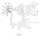
- the upper circuit branch according to FIG. 1 is developed in such a way that two test sensors 82, 84 are arranged next to the thermopile 16.
- the processing of the signal emitted by the thermopile 16 corresponds to that described in FIG. 1. An exact explanation of this is therefore omitted.
- the radiation 10 falls on a protective glass 80 which transmits the radiation in a wide wavelength range.
- the interference filter 14 filters out a fire-specific wavelength range from this wavelength range, which reaches the thermopile 16.
- Another part of the radiation 10 reaches the test sensors 82 and 84. These are silicon photodiodes, whose maximum spectral sensitivity is in the range below 1 micron wavelength of the radiation lies.
- test sensors are connected in series on their opposite-pole electrodes and connected to a differential amplifier 88, which amplifies the test signal output by sensors 82, 84.
- the protective glass 80 can become dirty during operation of the fire alarm, which is indicated by a dirt coating 92 in FIG. 2.
- This dirt coating weakens the intensity of the incident radiation 10 and thereby reduces the sensitivity of the fire detector for detecting fires.
- the radiation 10 of the room is mixed with a test radiation 94 having a certain wavelength, which is adapted to the spectral sensitivity of the sensors 82, 84, and a certain intensity.
- This test radiation 94 is additionally modulated with a frequency.
- the signal from the test sensors 82, 84 now contains components which originate both from the test radiation 94 and from the spatial radiation 10.
- the signal is amplified in the differential amplifier 88 and fed to a bandpass filter 90, which serves as a demodulator.
- the deviation from this limit value is a measure of the attenuation of the total radiation through the protective glass 80.
- the result of the comparison is then passed on to the transmission module 86 via a digital output of the bandpass filter 90, which forwards it to the central station after a parallel-series conversion.
- the control center can use this to infer the functionality of the fire detector and appropriate countermeasures initiate.
- FIG. 2 can be used not only for fire detectors that are equipped with thermocouples or thermopiles, but also for other types of sensor elements that are provided with a protective glass. It is only necessary for this that the test radiation has characteristic differences from the radiation which are evaluated for the detection of a fire. Such characteristic differences can lie in the modulation frequency, in the wavelength of the radiation and in the polarization state of the radiation.
Landscapes
- Business, Economics & Management (AREA)
- Emergency Management (AREA)
- Physics & Mathematics (AREA)
- General Physics & Mathematics (AREA)
- Fire-Detection Mechanisms (AREA)
- Fire Alarms (AREA)
Applications Claiming Priority (2)
| Application Number | Priority Date | Filing Date | Title |
|---|---|---|---|
| DE3924250 | 1989-07-21 | ||
| DE3924250A DE3924250A1 (de) | 1989-07-21 | 1989-07-21 | Branddetektor |
Publications (3)
| Publication Number | Publication Date |
|---|---|
| EP0409266A2 EP0409266A2 (de) | 1991-01-23 |
| EP0409266A3 EP0409266A3 (en) | 1991-08-14 |
| EP0409266B1 true EP0409266B1 (de) | 1996-01-17 |
Family
ID=6385582
Family Applications (1)
| Application Number | Title | Priority Date | Filing Date |
|---|---|---|---|
| EP90113961A Expired - Lifetime EP0409266B1 (de) | 1989-07-21 | 1990-07-20 | Branddetektor |
Country Status (4)
| Country | Link |
|---|---|
| EP (1) | EP0409266B1 (https=) |
| AT (1) | ATE133284T1 (https=) |
| DE (2) | DE3924250A1 (https=) |
| ES (1) | ES2084624T3 (https=) |
Families Citing this family (7)
| Publication number | Priority date | Publication date | Assignee | Title |
|---|---|---|---|---|
| DE4331574C2 (de) * | 1993-09-16 | 1997-07-10 | Heimann Optoelectronics Gmbh | Infrarot-Sensormodul |
| RU2170951C2 (ru) * | 1999-10-18 | 2001-07-20 | Закрытое акционерное общество Производственное объединение "Спецавтоматика" | Автономное пожарное сигнально-пусковое устройство |
| DE10011411C2 (de) | 2000-03-09 | 2003-08-14 | Bosch Gmbh Robert | Bildgebender Brandmelder |
| DE10154923A1 (de) * | 2001-11-08 | 2003-06-05 | Klaus Palme | Verfahren zur Gewinnung elektrischer Energie aus den Temperaturschwankungen der Luft |
| GB2426578A (en) | 2005-05-27 | 2006-11-29 | Thorn Security | A flame detector having a pulsing optical test source that simulates the frequency of a flame |
| GB2426577A (en) | 2005-05-27 | 2006-11-29 | Thorn Security | An optical detector with a reflector outside of its housing, and a plurality of sensors inside of its housing |
| RU2744900C1 (ru) * | 2020-03-23 | 2021-03-17 | Закрытое акционерное общество "Производственное объединение "Спецавтоматика" | Способ автоматического контроля пожарной опасности и автономное пожарное сигнально-пусковое устройство для его реализации |
Family Cites Families (10)
| Publication number | Priority date | Publication date | Assignee | Title |
|---|---|---|---|---|
| US2834008A (en) * | 1953-04-28 | 1958-05-06 | Petcar Res Corp | Flame detector system |
| US3518654A (en) * | 1967-05-16 | 1970-06-30 | American District Telegraph Co | Method and apparatus for detecting a condition |
| CH565421A5 (https=) * | 1974-05-10 | 1975-08-15 | Cerberus Ag | |
| JPS5727109Y2 (https=) * | 1974-07-20 | 1982-06-12 | ||
| CA1023971A (en) * | 1975-04-18 | 1978-01-10 | Canada Wire And Cable Limited | Variable temperature sensor |
| US4003038A (en) * | 1975-06-09 | 1977-01-11 | Multi-State Devices Ltd. | Thermal discriminator for sensing variations in the heat exchange properties of a medium |
| CH628171A5 (de) * | 1978-04-25 | 1982-02-15 | Cerberus Ag | Flammenmelder. |
| GB2089503B (en) * | 1980-12-12 | 1984-07-18 | Graviner Ltd | Fire and explosion detection |
| GB2175686A (en) * | 1985-05-28 | 1986-12-03 | Graviner Ltd | Fire or explosion detection arrangement |
| DE8528659U1 (de) * | 1985-10-08 | 1987-03-19 | Heimann Gmbh, 6200 Wiesbaden | Infrarotdetektor |
-
1989
- 1989-07-21 DE DE3924250A patent/DE3924250A1/de active Granted
-
1990
- 1990-07-20 DE DE59010065T patent/DE59010065D1/de not_active Expired - Fee Related
- 1990-07-20 ES ES90113961T patent/ES2084624T3/es not_active Expired - Lifetime
- 1990-07-20 AT AT90113961T patent/ATE133284T1/de not_active IP Right Cessation
- 1990-07-20 EP EP90113961A patent/EP0409266B1/de not_active Expired - Lifetime
Also Published As
| Publication number | Publication date |
|---|---|
| DE59010065D1 (de) | 1996-02-29 |
| DE3924250A1 (de) | 1991-02-07 |
| ES2084624T3 (es) | 1996-05-16 |
| EP0409266A2 (de) | 1991-01-23 |
| EP0409266A3 (en) | 1991-08-14 |
| DE3924250C2 (https=) | 1992-04-23 |
| ATE133284T1 (de) | 1996-02-15 |
Similar Documents
| Publication | Publication Date | Title |
|---|---|---|
| DE69032686T2 (de) | Infrarotsensor geeignet für anwendungen zur feuerbekämpfung | |
| US5339070A (en) | Combined UV/IR flame detection system | |
| US4206454A (en) | Two channel optical flame detector | |
| DE69901080T2 (de) | Sensor mit mehreren Arrays und Verfahren zur Identifizierung von Ereignissen in dem er benützt wird | |
| EP0966660B1 (de) | Thermopile-sensor und strahlungsthermometer mit einem thermopile-sensor | |
| DE69028046T2 (de) | Strahlungsabschirmung für thermoelektrisch gekühlte Infrarotdetektoren | |
| DE69820308T2 (de) | Mikrotechnologischer ableitender optisch-thermischer Gassensor | |
| DE69827389T2 (de) | Photothermischer mikrotechnologisch hergestellter gassensor | |
| DE2057221C3 (de) | Vorrichtung zur Feststellung von Flammen mittels wenigstens zwei photoelektrischen Anordnungen | |
| US4463260A (en) | Flame detector | |
| EP1343446B1 (de) | Blendschutzvorrichtung für schweisserschutzmasken | |
| DE2225319B2 (de) | Nichtdispersiver optischer Strahlung sanalysator | |
| EP0409266B1 (de) | Branddetektor | |
| WO1981000636A1 (fr) | Dispositif de detection avec detecteur | |
| EP1062647A1 (de) | Brandmelder | |
| DE2413482C3 (de) | Einrichtung zur Überwachung einer einzelnen Brennerflamme in einer eine Mehrzahl von Brennerflammen aufweisenden Brennkammer | |
| DE19654773C1 (de) | Verfahren und Vorrichtung zur betrieblichen Messung der Temperatur in mindestens einer Kochzone eines Kochfeldes mit einer Glaskeramikplatte | |
| DE2709866C2 (de) | Vorrichtung zur Feststellung von Schwebeteilchen | |
| DE3149869C2 (https=) | ||
| EP2758948B1 (de) | Brandmelder mit sensorfeld | |
| DE10245822A1 (de) | Verfahren und Gasmesszelle zur Detektion unterschiedlicher Gase | |
| DE102014018722B3 (de) | Verfahren, SiC-Halbleiterdetektor und dessen Verwendung und Detektoranordnung diesen aufweisend zur Detektion von Sonnenlicht | |
| DE60003885T2 (de) | Thermischer detektor mit begrenztem sichtwinkel | |
| AT390326B (de) | Verfahren zur temperaturmessung eines objektes mittels strahlungspyrometrie | |
| EP3074740B1 (de) | Leuchte und verfahren zur temperaturüberwachung |
Legal Events
| Date | Code | Title | Description |
|---|---|---|---|
| PUAI | Public reference made under article 153(3) epc to a published international application that has entered the european phase |
Free format text: ORIGINAL CODE: 0009012 |
|
| AK | Designated contracting states |
Kind code of ref document: A2 Designated state(s): AT BE CH DE DK ES FR GB GR IT LI LU NL SE |
|
| RBV | Designated contracting states (corrected) |
Designated state(s): AT BE DE ES FR GB NL |
|
| PUAL | Search report despatched |
Free format text: ORIGINAL CODE: 0009013 |
|
| AK | Designated contracting states |
Kind code of ref document: A3 Designated state(s): AT BE CH DE DK ES FR GB GR IT LI LU NL SE |
|
| 17P | Request for examination filed |
Effective date: 19910912 |
|
| 17Q | First examination report despatched |
Effective date: 19940627 |
|
| GRAA | (expected) grant |
Free format text: ORIGINAL CODE: 0009210 |
|
| AK | Designated contracting states |
Kind code of ref document: B1 Designated state(s): AT BE DE ES FR GB NL |
|
| REF | Corresponds to: |
Ref document number: 133284 Country of ref document: AT Date of ref document: 19960215 Kind code of ref document: T |
|
| REF | Corresponds to: |
Ref document number: 59010065 Country of ref document: DE Date of ref document: 19960229 |
|
| GBT | Gb: translation of ep patent filed (gb section 77(6)(a)/1977) |
Effective date: 19960227 |
|
| ET | Fr: translation filed | ||
| REG | Reference to a national code |
Ref country code: ES Ref legal event code: FG2A Ref document number: 2084624 Country of ref document: ES Kind code of ref document: T3 |
|
| PLBE | No opposition filed within time limit |
Free format text: ORIGINAL CODE: 0009261 |
|
| STAA | Information on the status of an ep patent application or granted ep patent |
Free format text: STATUS: NO OPPOSITION FILED WITHIN TIME LIMIT |
|
| RAP2 | Party data changed (patent owner data changed or rights of a patent transferred) |
Owner name: MINIMAX GMBH |
|
| 26N | No opposition filed | ||
| NLT2 | Nl: modifications (of names), taken from the european patent patent bulletin |
Owner name: MINIMAX GMBH |
|
| REG | Reference to a national code |
Ref country code: GB Ref legal event code: IF02 |
|
| BECN | Be: change of holder's name |
Owner name: *MINIMAX HOLDING G.M.B.H. & CO. K.G. Effective date: 20050928 |
|
| REG | Reference to a national code |
Ref country code: ES Ref legal event code: PC2A |
|
| REG | Reference to a national code |
Ref country code: FR Ref legal event code: TP Ref country code: FR Ref legal event code: CD |
|
| PGFP | Annual fee paid to national office [announced via postgrant information from national office to epo] |
Ref country code: ES Payment date: 20070704 Year of fee payment: 18 |
|
| PGFP | Annual fee paid to national office [announced via postgrant information from national office to epo] |
Ref country code: AT Payment date: 20070607 Year of fee payment: 18 |
|
| BECN | Be: change of holder's name |
Owner name: *MINIMAX G.M.B.H. & CO. K.G. Effective date: 20050928 |
|
| PGFP | Annual fee paid to national office [announced via postgrant information from national office to epo] |
Ref country code: BE Payment date: 20070711 Year of fee payment: 18 |
|
| PGFP | Annual fee paid to national office [announced via postgrant information from national office to epo] |
Ref country code: FR Payment date: 20070611 Year of fee payment: 18 |
|
| PGFP | Annual fee paid to national office [announced via postgrant information from national office to epo] |
Ref country code: DE Payment date: 20080710 Year of fee payment: 19 |
|
| PGFP | Annual fee paid to national office [announced via postgrant information from national office to epo] |
Ref country code: NL Payment date: 20080619 Year of fee payment: 19 |
|
| PGFP | Annual fee paid to national office [announced via postgrant information from national office to epo] |
Ref country code: GB Payment date: 20080620 Year of fee payment: 19 |
|
| PG25 | Lapsed in a contracting state [announced via postgrant information from national office to epo] |
Ref country code: AT Free format text: LAPSE BECAUSE OF NON-PAYMENT OF DUE FEES Effective date: 20080720 |
|
| REG | Reference to a national code |
Ref country code: FR Ref legal event code: ST Effective date: 20090331 |
|
| PG25 | Lapsed in a contracting state [announced via postgrant information from national office to epo] |
Ref country code: FR Free format text: LAPSE BECAUSE OF NON-PAYMENT OF DUE FEES Effective date: 20080731 |
|
| REG | Reference to a national code |
Ref country code: ES Ref legal event code: FD2A Effective date: 20080721 |
|
| PG25 | Lapsed in a contracting state [announced via postgrant information from national office to epo] |
Ref country code: ES Free format text: LAPSE BECAUSE OF NON-PAYMENT OF DUE FEES Effective date: 20080721 |
|
| GBPC | Gb: european patent ceased through non-payment of renewal fee |
Effective date: 20090720 |
|
| NLV4 | Nl: lapsed or anulled due to non-payment of the annual fee |
Effective date: 20100201 |
|
| PG25 | Lapsed in a contracting state [announced via postgrant information from national office to epo] |
Ref country code: GB Free format text: LAPSE BECAUSE OF NON-PAYMENT OF DUE FEES Effective date: 20090720 |
|
| PG25 | Lapsed in a contracting state [announced via postgrant information from national office to epo] |
Ref country code: DE Free format text: LAPSE BECAUSE OF NON-PAYMENT OF DUE FEES Effective date: 20100202 |
|
| PG25 | Lapsed in a contracting state [announced via postgrant information from national office to epo] |
Ref country code: BE Free format text: LAPSE BECAUSE OF NON-PAYMENT OF DUE FEES Effective date: 20080731 |
|
| PG25 | Lapsed in a contracting state [announced via postgrant information from national office to epo] |
Ref country code: NL Free format text: LAPSE BECAUSE OF NON-PAYMENT OF DUE FEES Effective date: 20100201 |