EP0409266B1 - Fire detector - Google Patents
Fire detector Download PDFInfo
- Publication number
- EP0409266B1 EP0409266B1 EP90113961A EP90113961A EP0409266B1 EP 0409266 B1 EP0409266 B1 EP 0409266B1 EP 90113961 A EP90113961 A EP 90113961A EP 90113961 A EP90113961 A EP 90113961A EP 0409266 B1 EP0409266 B1 EP 0409266B1
- Authority
- EP
- European Patent Office
- Prior art keywords
- radiation
- thermocouple
- fire detector
- fire
- test
- Prior art date
- Legal status (The legal status is an assumption and is not a legal conclusion. Google has not performed a legal analysis and makes no representation as to the accuracy of the status listed.)
- Expired - Lifetime
Links
- 230000005855 radiation Effects 0.000 claims abstract description 57
- 238000012360 testing method Methods 0.000 claims abstract description 38
- 239000011521 glass Substances 0.000 claims abstract description 11
- 230000001681 protective effect Effects 0.000 claims abstract description 11
- 238000011156 evaluation Methods 0.000 claims description 8
- 230000003287 optical effect Effects 0.000 claims description 3
- 239000000919 ceramic Substances 0.000 claims description 2
- 239000000758 substrate Substances 0.000 claims 1
- 230000035945 sensitivity Effects 0.000 abstract description 11
- 238000010438 heat treatment Methods 0.000 abstract description 3
- 238000010521 absorption reaction Methods 0.000 abstract description 2
- 230000005540 biological transmission Effects 0.000 abstract description 2
- 238000011144 upstream manufacturing Methods 0.000 abstract description 2
- 230000003595 spectral effect Effects 0.000 description 4
- 238000011109 contamination Methods 0.000 description 3
- 238000001514 detection method Methods 0.000 description 3
- 238000011161 development Methods 0.000 description 3
- 239000004065 semiconductor Substances 0.000 description 3
- 238000006243 chemical reaction Methods 0.000 description 2
- 239000011248 coating agent Substances 0.000 description 2
- 238000000576 coating method Methods 0.000 description 2
- 230000007423 decrease Effects 0.000 description 2
- 238000012546 transfer Methods 0.000 description 2
- 230000005678 Seebeck effect Effects 0.000 description 1
- XUIMIQQOPSSXEZ-UHFFFAOYSA-N Silicon Chemical compound [Si] XUIMIQQOPSSXEZ-UHFFFAOYSA-N 0.000 description 1
- 230000006978 adaptation Effects 0.000 description 1
- 239000012080 ambient air Substances 0.000 description 1
- 238000009529 body temperature measurement Methods 0.000 description 1
- 230000003247 decreasing effect Effects 0.000 description 1
- 238000005516 engineering process Methods 0.000 description 1
- 229910052732 germanium Inorganic materials 0.000 description 1
- GNPVGFCGXDBREM-UHFFFAOYSA-N germanium atom Chemical compound [Ge] GNPVGFCGXDBREM-UHFFFAOYSA-N 0.000 description 1
- 238000005338 heat storage Methods 0.000 description 1
- 239000000463 material Substances 0.000 description 1
- 238000005259 measurement Methods 0.000 description 1
- 239000000203 mixture Substances 0.000 description 1
- 239000002245 particle Substances 0.000 description 1
- 230000035699 permeability Effects 0.000 description 1
- 230000010287 polarization Effects 0.000 description 1
- 238000012545 processing Methods 0.000 description 1
- 229910052710 silicon Inorganic materials 0.000 description 1
- 239000010703 silicon Substances 0.000 description 1
Images

Classifications
-
- G—PHYSICS
- G08—SIGNALLING
- G08B—SIGNALLING OR CALLING SYSTEMS; ORDER TELEGRAPHS; ALARM SYSTEMS
- G08B17/00—Fire alarms; Alarms responsive to explosion
- G08B17/12—Actuation by presence of radiation or particles, e.g. of infrared radiation or of ions
Definitions
- the invention relates to a fire detector according to the preamble of claim 1.
- a fire detector is described in DE 25 12 650 C2, which has a sensor element that detects the radiation emitted by a flame. The spectral composition of the radiation is analyzed and an alarm signal is generated depending on the result. Semiconductor components such as photodiodes or photo elements are used as the sensor element. These have the disadvantage that their interference signal spacing, ie the ratio of the useful signal to the interference signal, decreases sharply with increasing ambient temperature, since at high temperatures their interference signal is high, for example as a result of thermal noise, and their sensitivity decreases. The ambient temperature can vary widely when operating fire detectors Fluctuate range.
- Typical operating temperatures of fire detectors range, for example, from -40 ° C to + 60 ° and higher in the event of a fire, at which the fire detector should still work properly.
- the response threshold of the useful signal ie the signal that can trigger an alarm, must be greater than the maximum interference signal.
- thermocouple A fire detector is known from US Pat. No. 2,834,008, the sensor element of which is designed as a thermocouple.
- the AC voltage signal emitted by the thermocouple is evaluated within a predetermined frequency range.
- an evaluation unit If the signal amplitudes typical for a fire occur in the range from 3 to 30 Hz, an evaluation unit generates an alarm signal.
- thermocouples for temperature measurement.
- the voltage generated by a thermocouple depends on the temperature difference between the measuring point and the reference point.
- the reference junction temperature must be kept at a known temperature that is as constant as possible.
- the thermocouple generates a voltage depending on the temperature difference between its measuring point and its reference point.
- the reference junction is connected to a heat sink, which assumes the temperature of the room as a result of heat conduction. Since the heat sink stores heat, short-term temperature fluctuations of the room follow only slowly, so that a temperature is established over time on the heat sink which corresponds approximately to the mean temperature of the room.
- the measuring point of the thermocouple has a small heat capacity and can Follow temperature changes quickly. Accordingly, the temperature of the measuring point of the thermocouple is influenced by absorption of radiation energy, which emits a heat source, and / or by heating due to heat conduction, for example by thermal convection. In the event of a fire, both types of heat transfer are effective, ie the thermocouple detects parts of both forms of energy. This increases the sensitivity of the fire detector to the known device.
- thermocouple emits a signal that is proportional to the temperature difference between the reference point and the measuring point, regardless of the absolute temperature.
- the absolute temperature of the room does not affect the sensitivity of the fire detector.
- the interference signal from thermocouples is small over a wide temperature range, since their thermal noise is smaller than that from semiconductor components.
- the fire detector therefore has an almost constant signal-to-noise ratio over its entire operating temperature range. This makes it possible to select the response threshold for detecting a fire accordingly low, so that fires can be detected early. Since, unlike in the prior art, no semiconductor component is used as the sensor element, which is known to have a low limit temperature, the temperature range in which the fire detector can be used is also enlarged compared to the prior art. The consequence of this is that the fire detector remains functional even at high temperatures, for example in the event of a fire, and can provide information about the course of the fire.
- thermocouples are connected together to form a thermopile. This measure increases the sensitivity of the fire detector even further.
- thermocouple is preceded by an optical filter which is transparent to radiation of a wavelength specific to the fire.
- the flames emit radiation with a characteristic wavelength that differs from the wavelength of other heat sources.
- the measures mentioned effectively suppress interference radiation from heat sources, such as incandescent lamps, radiators, etc.
- the alarm signal can be generated depending on the exceeding of a predetermined threshold value of the signal of the thermocouple and / or depending on the flicker frequency of the signal.
- the frequency of the radiation emanating from a fire can also be used to distinguish the radiation emanating from a fire from interference radiation.
- the frequency at which a flame emits radiation is normally in a frequency range from 0.5 to 10 Hz. If the evaluation of the signals from the thermocouple is limited to this frequency range, the interference signal from the interference radiation of other heat sources with deviating frequencies can , such as ambient light with a frequency of 0 Hz or radiation from an incandescent lamp with a frequency of 100 Hz, do not distort the result.
- the response of the fire detector to fires becomes even more selective and therefore more reliable.
- thermocouple which can receive test radiation and which emits a test signal to the evaluation unit which, depending on its size, generates a state signal indicating the functional state of the fire detector, and that A protective glass is connected upstream of the thermocouple and the test sensor, which is broadband transparent to radiation.
- Fire detectors which among other things also evaluate the radiation for fire detection, are naturally sensitive to contamination, since the radiation is already absorbed by dirt particles before they reach the radiation-sensitive surface of the sensor element. This reduces the sensitivity of the fire detector and, at a certain degree of contamination, the fire detector can no longer function properly. This is also critical because the other electrical functions of the fire detector still work properly when contaminated, so that an electrical test cannot provide any information about the functionality of the band detector.
- at least two sensor elements namely the thermocouple and the test sensor, are preceded by a protective glass. This is exposed to the ambient air and can become dirty. The permeability of the protective glass for broadband radiation is determined with the help of the test sensor.
- thermocouple Its spectral sensitive speed can be in a different wavelength range than the radiation detected by the thermocouple, since it can be assumed that the dirt on the protective glass generally attenuates the incident radiation over a broad band.
- the fire detector is functional both with regard to its electrical function and with regard to its ability to detect radiation from a fire.
- the aforementioned embodiment of the invention can be developed in a sensible manner such that the test radiation is modulated and a demodulator module is provided in the evaluation unit for demodulating the test signal. It is thereby achieved that the signal which is caused by the test radiation differs significantly from the signal of the radiation from other radiation sources.
- the test signal thus has a high signal-to-noise ratio, so that the degree of contamination of the protective glass can be determined with high reliability.
- thermopile 16 arranged in the upper circuit branch in FIG. 1 receives radiation 10 through an optical radiation-transmissive cover 12, from which an interference filter 14 passes a wavelength range characteristic of a fire.
- the thermopile 16 has a reference junction which is connected to a heat sink 18. This consists of a heat-storing material, such as ceramic, and is exposed to the ambient temperature of the room. The heat storage causes short-term temperature fluctuations in the room to be averaged out, so that an average temperature Tm is established on the heat sink 18.
- the measuring point of the thermopile 16 is supplied with the radiation transmitted by the interference filter 14, which heats it. Furthermore, a heat flow 20 with the temperature Tw can also act on the measuring point. This heat flow 20 can arise, for example, as a result of heat convection in the event of a fire and is therefore used in addition to the radiation 10 for fire detection. A temperature T1 thus arises at the measuring point of the thermopile 16, which has arisen from different energy transfer, namely through thermal convection and thermal radiation.
- the measuring point has a smaller heat capacity than the reference point thermally connected to the heat sink 18, so that it can follow short-term fluctuations in the radiation 10 and / or the heat flow 20.
- the temperature difference between the measuring point and the reference point of the thermopile 16 generates after Seebeck effect an electrical voltage, which is amplified by a matching amplifier 22, the impedance of which is matched to the internal resistance of the thermopile 16.
- the output signal of the adaptation amplifier 22 is fed to an amplifier 24, a frequency analyzer 26 and a differential amplifier 28.
- Limit modules 30, 32 and 34 are connected downstream of these modules 24, 26, 28.
- the amplifier 24 and the limit indicator 30 work together in such a way that they emit a signal to a logic module 68 at a predetermined temperature difference between the measuring point and the comparison point of the thermopile 16.
- the frequency analyzer 26 determines whether a flicker frequency is present in the signal from the thermopile and emits a corresponding signal to the link module 68 via the limit value detector 32.
- the differential amplifier 28 is used to determine the sign of the temperature change. The sign can again be used to determine whether the temperature of the measuring point of the thermopile 16 is increasing or decreasing. This information can be used to conclude, for example, that the fire has subsided.
- the lower circuit branch of the fire detector is constructed in the same way as the upper circuit branch, its corresponding components 42 to 64 therefore do not need to be explained in detail except for a few differences.
- no heat flow acts on the measuring point of the thermopile 46, so that only the radiation energy of the radiation 10 is evaluated.
- the link module 68 links the signals of the limit indicators 30 to 64 according to predetermined linking rules that are stored in a program block 70.
- an alarm signal can then be generated at the output 72 of the link module 68, which signals a fire condition when the temperature differences of the heating columns 16 and 46 exceed a predetermined value, the frequency analyzers 26 and 56 signal a certain flicker frequency and when the differential amplifiers 28 and 58 also signals deliver that correspond to a positive slope.
- the signals of limit value modules 30 to 34 and 60 to 64 are also conceivable, which define a dangerous state.
- the signals of the modules 24 to 28 and 54 to 58 are also fed to an output module 66 which, after a parallel-serial conversion, transmits them via an output 74 to a control center (not shown). These signals can be further evaluated there.
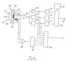
- the upper circuit branch according to FIG. 1 is developed in such a way that two test sensors 82, 84 are arranged next to the thermopile 16.
- the processing of the signal emitted by the thermopile 16 corresponds to that described in FIG. 1. An exact explanation of this is therefore omitted.
- the radiation 10 falls on a protective glass 80 which transmits the radiation in a wide wavelength range.
- the interference filter 14 filters out a fire-specific wavelength range from this wavelength range, which reaches the thermopile 16.
- Another part of the radiation 10 reaches the test sensors 82 and 84. These are silicon photodiodes, whose maximum spectral sensitivity is in the range below 1 micron wavelength of the radiation lies.
- test sensors are connected in series on their opposite-pole electrodes and connected to a differential amplifier 88, which amplifies the test signal output by sensors 82, 84.
- the protective glass 80 can become dirty during operation of the fire alarm, which is indicated by a dirt coating 92 in FIG. 2.
- This dirt coating weakens the intensity of the incident radiation 10 and thereby reduces the sensitivity of the fire detector for detecting fires.
- the radiation 10 of the room is mixed with a test radiation 94 having a certain wavelength, which is adapted to the spectral sensitivity of the sensors 82, 84, and a certain intensity.
- This test radiation 94 is additionally modulated with a frequency.
- the signal from the test sensors 82, 84 now contains components which originate both from the test radiation 94 and from the spatial radiation 10.
- the signal is amplified in the differential amplifier 88 and fed to a bandpass filter 90, which serves as a demodulator.
- the deviation from this limit value is a measure of the attenuation of the total radiation through the protective glass 80.
- the result of the comparison is then passed on to the transmission module 86 via a digital output of the bandpass filter 90, which forwards it to the central station after a parallel-series conversion.
- the control center can use this to infer the functionality of the fire detector and appropriate countermeasures initiate.
- FIG. 2 can be used not only for fire detectors that are equipped with thermocouples or thermopiles, but also for other types of sensor elements that are provided with a protective glass. It is only necessary for this that the test radiation has characteristic differences from the radiation which are evaluated for the detection of a fire. Such characteristic differences can lie in the modulation frequency, in the wavelength of the radiation and in the polarization state of the radiation.
Abstract
Description
Die Erfindung betrifft einen branddetektor, nach dem Oberbegriff des Anspruchs 1.The invention relates to a fire detector according to the preamble of claim 1.
Ein Branddetektor wird in der DE 25 12 650 C2 beschrieben, der über ein Sensorelement verfügt, das die von einer Flamme ausgesandte Strahlung erfaßt . Die spektrale Zusammensetzung der Strahlung wird analysiert und abhängig vom Ergebnis wird ein Alarmsignal erzeugt. Als Sensorelement werden Halbleiterbauelemente wie beispielsweise Fotodioden oder Fotoelemente verwendet. Diese haben den Nachteil, daß ihr Störsignalabstand, d.h. das Verhältnis von Nutzsignal zu Störsignal, mit steigender Umgebungstemperatur stark abnimmt, da bei hohen Temperaturen einerseits ihr Störsignal, z.B. infolge thermischen Rauschens, groß ist und andererseits ihre Empfindlichkeit nachläßt. Die Umgebungstemperatur kann beim Betrieb von Branddetektoren in einem weiten Bereich schwanken. Typische Betriebstemperaturen von Branddetektoren reichen z.B. von -40°C bis +60° und höher im Brandfall, bei denen der Branddetektor noch einwandfrei arbeiten soll. Um Fehlauslösungen über den gesamten Temperaturbereich zu vermeiden, muß die Ansprechschwelle des Nutzsignals, d.h. das Signal, das gerade einen Alarm auszulösen vermag, größer sein als das maximale Störsignal. Dies bedeutet aber, daß die Ansprechempfindlichkeit des Branddetektors niedrig ist und seine Fähigkeit zur frühzeitigen Branderkennung vermindert ist.A fire detector is described in DE 25 12 650 C2, which has a sensor element that detects the radiation emitted by a flame. The spectral composition of the radiation is analyzed and an alarm signal is generated depending on the result. Semiconductor components such as photodiodes or photo elements are used as the sensor element. These have the disadvantage that their interference signal spacing, ie the ratio of the useful signal to the interference signal, decreases sharply with increasing ambient temperature, since at high temperatures their interference signal is high, for example as a result of thermal noise, and their sensitivity decreases. The ambient temperature can vary widely when operating fire detectors Fluctuate range. Typical operating temperatures of fire detectors range, for example, from -40 ° C to + 60 ° and higher in the event of a fire, at which the fire detector should still work properly. In order to avoid false triggering over the entire temperature range, the response threshold of the useful signal, ie the signal that can trigger an alarm, must be greater than the maximum interference signal. However, this means that the sensitivity of the fire detector is low and its ability to detect fire early is reduced.
Aus der US-A-2,834,008 ist ein Branddetektor bekannt, dessen Sensorelement als Thermoelement ausgebildet ist. Das vom Thermoelement abgegebene Wechselspannungssignal wird innerhalb eines vorgegebenen Frequenzbereiches ausgewertet.A fire detector is known from US Pat. No. 2,834,008, the sensor element of which is designed as a thermocouple. The AC voltage signal emitted by the thermocouple is evaluated within a predetermined frequency range.
Wenn die für einen Brand typischen Signalamplituden im Bereich von 3 bis 30 Hz auftreten, so erzeugt eine Auswerteeinheit ein Alarmsignal.If the signal amplitudes typical for a fire occur in the range from 3 to 30 Hz, an evaluation unit generates an alarm signal.
Aus M. Stöckl und K.H. Winterling, Elektrische Meßtechnik, Teubner-Verlag, Stuttgart, 1973, Seiten 302 bis 304, ist es bekannt, zur Temperaturmessung Thermopaare zu verwenden. Die von einem Thermopaar erzeugte Spannung hängt vom Temperaturunterschied zwischen der Meßstelle und der Vergleichsstelle ab. Zur Temperaturmessung muß die Vergleichsstellentemperatur auf eine bekannte, möglichst konstante Temperatur gehalten werden.From M. Stöckl and KH Winterling, Electrical Measurement Technology, Teubner-Verlag, Stuttgart, 1973, pages 302 to 304, it is known to use thermocouples for temperature measurement. The voltage generated by a thermocouple depends on the temperature difference between the measuring point and the reference point. To measure the temperature, the reference junction temperature must be kept at a known temperature that is as constant as possible.
Es ist Aufgabe der Erfindung einen Branddetektor anzugeben, der eine hohe Ansprechempfindlichkeit in einem großen Betriebstemperaturbereich besitzt.It is an object of the invention to provide a fire detector which has a high sensitivity in a wide operating temperature range.
Diese Aufgabe wird durch die Merkmale des Anspruchs 1 gelöst.This object is solved by the features of claim 1.
Das Thermoelement erzeugt abhängig von der Temperaturdifferenz zwischen seiner Meßstelle und seiner Vergleichsstelle eine Spannung. Gemäß der Erfindung ist die Vergleichsstelle mit einer Wärmesenke verbunden, die infolge Wärmeleitung die Temperatur des Raumes annimmt. Da die Wärmesenke Wärme speichert, folgt es kurzzeitigen Temperaturschwankungen des Raumes nur langsam, so daß sich über der Zeit auf der wärmesenke eine Temperatur einstellt, die etwa der mittleren Temperatur des Raumes entspricht. Die Meßstelle des Thermoelements hat eine kleine Wärmekapazität und kann Temperaturänderungen schnell folgen. Demgemäß wird die Temperatur der Meßstelle des Thermoelements durch Absorption von Strahlungsenergie, die eine Wärmequelle aussendet, und/oder durch Erwärmung infolge Wärmeleitung, beispielsweise durch Wärmekonvektion, beeinflußt. Im Brandfall sind beide Wärmeübertragungsarten wirksam, d.h. das Thermoelement erfaßt Anteile beider Energieformen. Dadurch wird die Empfindlichkeit des Branddetektors gegenüber dem bekannten Gerät erhöht.The thermocouple generates a voltage depending on the temperature difference between its measuring point and its reference point. According to the invention, the reference junction is connected to a heat sink, which assumes the temperature of the room as a result of heat conduction. Since the heat sink stores heat, short-term temperature fluctuations of the room follow only slowly, so that a temperature is established over time on the heat sink which corresponds approximately to the mean temperature of the room. The measuring point of the thermocouple has a small heat capacity and can Follow temperature changes quickly. Accordingly, the temperature of the measuring point of the thermocouple is influenced by absorption of radiation energy, which emits a heat source, and / or by heating due to heat conduction, for example by thermal convection. In the event of a fire, both types of heat transfer are effective, ie the thermocouple detects parts of both forms of energy. This increases the sensitivity of the fire detector to the known device.
Das Thermoelement gibt ein Signal ab, das der Temperaturdifferenz zwischen der Vergleichsstelle und der Meßstelle unabhängig von der absoluten Temperatur proportional ist. Dies bedeutet, daß die absolute Temperatur des Raumes die Empfindlichkeit des Branddetektors nicht beeinflußt. Weiterhin ist das Störsignal von Thermoelementen über einen weiten Temperaturbereich klein, da ihr thermisches Rauschen kleiner ist als das von Halbleiterbauelementen. Der Branddetektor hat daher über seinen gesamten Betriebstemperaturbereich einen annähernd konstanten Störabstand. Dadurch wird es möglich, die Ansprechschwelle für das Erkennen eines Brandes entsprechend niedrig zu wählen, so daß Brände frühzeitig erkannt werden können. Da als Sensorelement anders als beim Stand der Technik kein Halbleiterbauelement verwendet wird, das bekanntlich eine niedrige Grenztemperatur hat, ist auch der Temperaturbereich, in dem der Branddetektor eingesetzt werden kann, gegenüber dem Stand der Technik vergrößert. Dies hat zur Folge, daß der Branddetektor auch bei hohen Temperaturen, beispielsweise im Brandfall, noch funktionstüchtig bleibt und Informationen über den Brandverlauf liefern kann.The thermocouple emits a signal that is proportional to the temperature difference between the reference point and the measuring point, regardless of the absolute temperature. This means that the absolute temperature of the room does not affect the sensitivity of the fire detector. Furthermore, the interference signal from thermocouples is small over a wide temperature range, since their thermal noise is smaller than that from semiconductor components. The fire detector therefore has an almost constant signal-to-noise ratio over its entire operating temperature range. This makes it possible to select the response threshold for detecting a fire accordingly low, so that fires can be detected early. Since, unlike in the prior art, no semiconductor component is used as the sensor element, which is known to have a low limit temperature, the temperature range in which the fire detector can be used is also enlarged compared to the prior art. The consequence of this is that the fire detector remains functional even at high temperatures, for example in the event of a fire, and can provide information about the course of the fire.
Ein bevorzugtes Ausführungsbeispiel ist dadurch gekennzeichnet, daß mehrere Thermoelemente zu einer Thermosäule zusammengeschaltet sind. Durch diese Maßnahme wird die Empfindlichkeit des Branddetektors noch weiter gesteigert.A preferred embodiment is characterized in that several thermocouples are connected together to form a thermopile. This measure increases the sensitivity of the fire detector even further.
Bei einer anderen Ausgestaltung der Erfindung ist dem Thermoelement ein optisches Filter vorgeschaltet, das für Strahlung brandspezifischer Wellenlänge durchlässig ist. Bei einem Brand senden die Flammen Strahlung mit einer charakteristischen Wellenlänge aus, die sich von der Wellenlänge anderer Wärmequellen unterscheidet. Durch die genannten Maßnahmen wird die Störstrahlung von Wärmequellen, wie beispielsweise Glühlampen, Radiatoren, usw., wirksam unterdrückt.In another embodiment of the invention, the thermocouple is preceded by an optical filter which is transparent to radiation of a wavelength specific to the fire. In the event of a fire, the flames emit radiation with a characteristic wavelength that differs from the wavelength of other heat sources. The measures mentioned effectively suppress interference radiation from heat sources, such as incandescent lamps, radiators, etc.
Eine andere Weiterbildung zeichnet sich dadurch aus, daß das Alarmsignal abhängig vom Überschreiten eines vorgegebenen Schwellwertes des Signals des Thermoelements und/oder abhängig von der Flackerfrequenz des Signals erzeugbar ist. Zur Unterscheidung der von einem Brand ausgehenden Strahlung gegenüber einer Störstrahlung kann auch die Frequenz der von einem Brand ausgehenden Strahlung herangezogen werden. Die Frequenz mit der eine Flamme Strahlung aussendet, die sogenannte Flackerfrequenz, liegt normalerweise in einem Frequenzbereich von 0,5 bis 10 Hz. Beschränkt sich die Auswertung der Signale des Thermoelements auf diesen Frequenzbereich, so kann das Störsignal der Störstrahlung anderer Wärmequellen mit davon abweichenden Frequenzen, wie beispielsweise das Umgebungslicht mit einer Frequenz von 0 Hz oder die Strahlung einer Glühlampe mit einer Frequenz von 100 Hz, das Ergebnis nicht verfälschen. Bei einer kombinierten Auswertung, bei der die Größe des Signals des Thermoelements und das Vorliegen einer Flackerfrequenz Bedingungen für das Erzeugen des Alarmsignals sind, wird das Ansprechen des Branddetektors auf Brände noch selektiver und damit zuverlässiger.Another further development is characterized in that the alarm signal can be generated depending on the exceeding of a predetermined threshold value of the signal of the thermocouple and / or depending on the flicker frequency of the signal. The frequency of the radiation emanating from a fire can also be used to distinguish the radiation emanating from a fire from interference radiation. The frequency at which a flame emits radiation, the so-called flicker frequency, is normally in a frequency range from 0.5 to 10 Hz. If the evaluation of the signals from the thermocouple is limited to this frequency range, the interference signal from the interference radiation of other heat sources with deviating frequencies can , such as ambient light with a frequency of 0 Hz or radiation from an incandescent lamp with a frequency of 100 Hz, do not distort the result. In a combined evaluation, in which the size of the signal of the Thermocouples and the presence of a flickering frequency are conditions for generating the alarm signal, the response of the fire detector to fires becomes even more selective and therefore more reliable.
Eine vorteilhafte Weiterbildung der Erfindung zeichnet sich dadurch aus, daß nahe dem Thermoelement mindestens ein Testsensor angeordnet ist, der eine Teststrahlung empfangen kann und der ein Testsignal an die Auswerteeinheit abgibt, die abhängig von dessen Größe ein den Funktionszustand des Branddetektors angebendes Zustandssignal erzeugt, und daß dem Thermoelement sowie dem Testsensor ein Schutzglas vorgeschaltet ist, das für Strahlung breitbandig durchlässig ist.An advantageous development of the invention is characterized in that at least one test sensor is arranged near the thermocouple, which can receive test radiation and which emits a test signal to the evaluation unit which, depending on its size, generates a state signal indicating the functional state of the fire detector, and that A protective glass is connected upstream of the thermocouple and the test sensor, which is broadband transparent to radiation.
Branddetektoren, die unter anderem auch die Strahlung zur Branderkennung auswerten, sind naturgemäß empfindlich gegen Verschmutzung, da die Strahlung bereits von Schmutzpartikeln absorbiert wird, bevor sie auf die strahlungsempfindliche Fläche des Sensorelements gelangen. Die Empfindlichkeit des Branddetektors wird dadurch herabgesetzt, und bei einem bestimmten Verschmutzungsgrad kann der Branddetektor seine Funktion nicht mehr ordnungsgemäß erfüllen. Dies ist auch deshalb kritisch, weil die sonstigen elektrischen Funktionen des Branddetektors bei Verschmutzung noch einwandfrei arbeiten, so daß ein elektrischer Test keinen Aufschluß über die Funktionstüchtigkeit des Banddetektors geben kann. Bei der Weiterbildung werden nun mindestens zwei Sensorelementen, nämlich dem Thermoelement und dem Testsensor, ein Schutzglas vorgeschaltet. Dieses ist der Umgebungsluft ausgesetzt und kann verschmutzen. Die Durchlässigkeit des Schutzglases für breitbandige Strahlung wird mit Hilfe des Testsensors festgestellt. Dessen spektrale Empfindlich keit kann dabei in einem anderen Wellenlängenbereich liegen als die vom Thermoelement erfaßte Strahlung, da davon ausgegangen werden kann, daß der Schmutzbelag auf dem Schutzglas die einfallende Strahlung im allgemeinen breitbandig abschwächt. Anhand der Größe des vom Testsensor abgegebenen Testsignals kann auf die Funktionstüchtigkeit des Branddetektors sowohl hinsichtlich seiner elektrischen Funktion als auch hinsichtlich seiner Fähigkeit, Strahlung eines Brandes zu erfassen, geschlossen werden.Fire detectors, which among other things also evaluate the radiation for fire detection, are naturally sensitive to contamination, since the radiation is already absorbed by dirt particles before they reach the radiation-sensitive surface of the sensor element. This reduces the sensitivity of the fire detector and, at a certain degree of contamination, the fire detector can no longer function properly. This is also critical because the other electrical functions of the fire detector still work properly when contaminated, so that an electrical test cannot provide any information about the functionality of the band detector. In the development, at least two sensor elements, namely the thermocouple and the test sensor, are preceded by a protective glass. This is exposed to the ambient air and can become dirty. The permeability of the protective glass for broadband radiation is determined with the help of the test sensor. Its spectral sensitive speed can be in a different wavelength range than the radiation detected by the thermocouple, since it can be assumed that the dirt on the protective glass generally attenuates the incident radiation over a broad band. On the basis of the size of the test signal emitted by the test sensor, it can be concluded that the fire detector is functional both with regard to its electrical function and with regard to its ability to detect radiation from a fire.
Die vorgenannte Ausführungsform der Erfindung kann in sinnvoller Weise derart weitergebildet sein, daß die Teststrahlung moduliert ist und in der Auswerteeinheit zur Demodulation des Testsignals ein Demodulatorbaustein vorgesehen ist. Dadurch wird erreicht, daß sich das Signal, das von der Teststrahlung hervorgerufen wird, deutlich vom Signal der Strahlung anderer Strahlungsquellen unterscheidet. Das Testsignal hat somit einen hohen Störabstand, so daß der Verschmutzungsgrad des Schutzglases mit hoher Zuverlässigkeit festgestellt werden kann.The aforementioned embodiment of the invention can be developed in a sensible manner such that the test radiation is modulated and a demodulator module is provided in the evaluation unit for demodulating the test signal. It is thereby achieved that the signal which is caused by the test radiation differs significantly from the signal of the radiation from other radiation sources. The test signal thus has a high signal-to-noise ratio, so that the degree of contamination of the protective glass can be determined with high reliability.
Ausführungsbeispiele der Erfindung werden im folgenden anhand der Zeichnung erläutert. Darin zeigt:
- Fig. 1
- einen Branddetektor mit zwei Thermosäulen, die Strahlung unterschiedlicher Wellenlänge erfassen, und
- Fig. 2
- einen Branddetektor mit einer Thermosäule und zwei Testsensoren.
- Fig. 1
- a fire detector with two thermopiles that detect radiation of different wavelengths, and
- Fig. 2
- a fire detector with a thermopile and two test sensors.
In Fig. 1 ist schematisch ein Branddetektor nach der Erfindung dargestellt, der mit zwei als Thermosäulen 16, 46 ausgebildeten Sensorelementen ausgerüstet ist. Die im oberen Schaltungszweig in der Fig. 1 angeordnete Thermosäule 16 empfängt durch eine optische strahlungsdurchlässige Abdeckung 12 eine Strahlung 10, von der ein Interferenz filter 14 einen für einen Brand charakteristischen Wellenlängebereich durchläßt. Die Thermosäule 16 hat eine Vergleichsstelle, die mit einer Wärmesenke 18 verbunden ist. Diese besteht aus einem wärmespeichernden Material, wie beispielsweise Keramik, und ist der Umgebungstemperatur des Raumes ausgesetzt. Die Wärmespeicherung bewirkt, daß kurzzeitige Temperaturschwankungen des Raumes ausgemittelt werden, so daß sich auf der Wärmesenke 18 eine mittlere Temperatur Tm einstellt.1 schematically shows a fire detector according to the invention, which is equipped with two sensor elements designed as
Der Meßstelle der Thermosäule 16 wird die vom Interferenzfilter 14 durchgelassene Strahlung zugeführt, die diese erwärmt. Ferner kann auf die Meßstelle auch ein Wärmestrom 20 mit der Temperatur Tw einwirken. Dieser Wärmestrom 20 kann zum Beispiel infolge der Wärmekonvektion bei einem Brand entstehen und wird daher neben der Strahlung 10 zusätzlich zur Branderkennung ausgenutzt. Auf der Meßstelle der Thermosäule 16 stellt sich somit eine Temperatur T1 ein, die durch unterschiedliche Energieübertragung entstanden ist, nämlich durch Wärmekonvektion und Wärmestrahlung.The measuring point of the
Die Meßstelle hat eine kleinere Wärmekapazität als die mit der Wärmesenke 18 thermisch verbundene Vergleichsstelle, so daß sie kurzzeitigen Schwankungen der Strahlung 10 und/oder des Wärmestroms 20 folgen kann. Die Temperaturdifferenz zwischen der Meßstelle und der Vergleichsstelle der Thermosäule 16 erzeugt nach dem Seebeck-Effekt eine elektrische Spannung, die von einem Anpassungsverstärker 22, dessen Impedanz dem Innenwiderstand der Thermosäule 16 angepaßt ist, verstärkt wird. Das Ausgangssignal des Anpassungsverstärkers 22 wird einem Verstärker 24, einem Frequenzanalysator 26 sowie einem Differentialverstärker 28 zugeführt. Diesen Bausteinen 24, 26, 28 sind jeweils Grenzwertmelder 30, 32 bzw. 34 nachgeschaltet. Der Verstärker 24 und der Grenzwertmelder 30 wirken so zusammen, daß sie bei einer vorgegebenen Temperaturdifferenz zwischen der Meßstelle und der Vergleichsstelle der Thermosäule 16 ein Signal an einen Verknüpfungsbaustein 68 abgeben. Der Frequenzanalysator 26 stellt fest, ob im Signal der Thermosäule eine Flackerfrequenz vorhanden ist und gibt über den Grenzwertmelder 32 ein entspechendes Signal an den Verknüpfungsbaustein 68 ab. Mit Hilfe des Differentialverstärkers 28 wird festgestellt, welches Vorzeichen die Temperaturänderung hat. Anhand des Vorzeichens kann wiederum festgestellt werden, ob die Temperatur der Meßstelle der Thermosäule 16 abnimmt oder zunimmt. Aus dieser Information kann beispielsweise auf ein Abklingen des Brandes geschlossen werden.The measuring point has a smaller heat capacity than the reference point thermally connected to the
Der untere Schaltungszweig des Branddetektors ist in gleicher Weise aufgebaut wie der obere Schaltungszweig, seine entsprechenden Bausteine 42 bis 64 müssen daher bis auf wenige Unterschiede nicht näher erläutert werden. Ein Unterschied besteht im Interferenzfilter 44, dessen Durchlaßbereich auf eine andere brandspezifische Wellenlänge abgestimmt ist als die des Interferenzfilters 14 des oberen Schaltungszweigs. Ferner wirkt auf die Meßstelle der Thermosäule 46 kein Wärmestrom ein, so daß allein die Strahlungsenergie der Strahlung 10 ausgewertet wird. Der Verknüpfungsbaustein 68 verknüpft die Signale der Grenzwertmelder 30 bis 64 nach vorgegebenen Verknüpfungsregeln, die in einem Programmbaustein 70 gespeichert sind. Beispielsweise kann am Ausgang 72 des Verknüpfungsbausteins 68 dann ein Alarmsignal erzeugt werden, das einen Brandzustand signalisiert, wenn die Temperaturdifferenzen der Wärmesäulen 16 und 46 einen vorgegebenen Wert überschreiten, die Frequenzanalysatoren 26 und 56 eine bestimmte Flackerfrequenz signalisieren und wenn ferner die Differentialverstärker 28 und 58 Signale abgeben, die einer positiven Steigung entsprechen. Es sind aber auch andere Verknüpfungen der Signale der Grenzwertbausteine 30 bis 34 und 60 bis 64 denkbar, die einen Gefahrenzustand definieren. Die Signale der Bausteine 24 bis 28 sowie 54 bis 58 werden ferner auf einen Ausgabebaustein 66 geführt, der sie nach einer Parallel-Serienumwandlung über einen Ausgang 74 zu einer Zentrale (nicht dargestellt) übermittelt. Dort können diese Signale weiter ausgewertet werden.The lower circuit branch of the fire detector is constructed in the same way as the upper circuit branch, its corresponding
In Fig. 2 ist der obere Schaltungszweig nach der Fig. 1 derart weitergebildet, daß neben der Thermosäule 16 zwei Testsensoren 82, 84 angeordnet sind. Die Verarbeitung des von der Thermosäule 16 abgegebenen Signals stimmt mit der bei der Fig. 1 beschriebenen überein. Auf eine genaue Erläuterung hierzu wird daher verzichtet. Beim Ausführungsbeispiel nach der Fig. 2 fällt die Strahlung 10 auf ein Schutzglas 80, welches die Strahlung in einem breiten Wellenlängenbereich durchläßt. Aus diesem Wellenlängenbereich filtert das Interferenzfilter 14 einen brandspezifischen Wellenlängenbereich aus, der auf die Thermosäule 16 gelangt. Ein anderer Teil der Strahlung 10 gelangt auf die Testsensoren 82 und 84. Diese sind Silizium-Photodioden, deren maximale spektrale Emfindlichkeit im Bereich unter 1 Mikrometer Wellenlänge der Strahlung liegt. Es sind jedoch auch andere Typen von Fotoempfängern einsetzbar wie beispielsweise Germanium-Photodioden, Fotoelemente, etc. Die Testsensoren sind an ihren gegenpoligen Elektroden in Reihe geschaltet und an einen Differenzverstärker 88 angeschlossen, der das von den Sensoren 82, 84 abgegebene Testsignal verstärkt.2, the upper circuit branch according to FIG. 1 is developed in such a way that two
Das Schutzglas 80 kann beim Betrieb des Brandmelders im Laufe der Zeit verschmutzen, was durch einen Schmutzbelag 92 in der Fig. 2 angedeutet ist. Dieser Schmutzbelag schwächt die Intensität der einfallenden Strahlung 10 und setzt dadurch die Empfindlichkeit des Branddetektors zum Erkennen von Bränden herab. Der Strahlung 10 des Raumes wird bei diesem Ausführungsbeispiel eine Teststrahlung 94 mit einer bestimmten, an die spektrale Empfindlichkeit der Sensoren 82, 84 angepaßten Wellenlänge sowie einer bestimmten Intensität zugemischt. Diese Teststrahlung 94 wird zusätzlich mit einer Frequenz moduliert. Im Signal der Testsensoren 82, 84 sind nun Anteile enthalten, die sowohl von der Teststrahlung 94 als auch von der Raumstrahlung 10 herrühren. Das Signal wird im Differenzverstärker 88 verstärkt und einem Bandpaßfilter 90 zugeführt, der als Demodulator dient. Dieses filtert den Signalanteil aus, der von der Teststrahlung 94 herrührt und vergleicht diesen mit einem vorgegebenen Grenzwert. Die Abweichung von diesem Grenzwert ist ein Maß für die Schwächung der Gesamtstrahlung durch das Schutzglas 80. Das Ergebnis des Vergleichs wird dann über einen Digitalausgang des Bandpaßfilters 90 an den Übertragungsbaustein 86 weitergegeben, der dieses nach einer Parallel-Serien-Umwandlung an die Zentrale weiterleitet. Die Zentrale kann daraus auf die Funktionstüchtigkeit des Brandmelders schließen und entsprechende Gegenmaßnahmen einleiten.The
Das Ausführungsbeispiel nach der Fig. 2 ist nicht nur für Branddetektoren verwendbar, die mit Thermoelementen oder Thermosäulen ausgerüstet sind, sondern auch für andere Arten von Sensorelementen, die mit einem Schutzglas versehen sind. Es ist hierzu lediglich erforderlich, daß die Teststrahlung charakteristische Unterschiede zu der Strahlung hat, die zur Erkennung eines Brandes ausgewertet werden. Solche charakteristischen Unterschiede können in der Modulationsfrequenz, in der Wellenlänge der Strahlung und im Polarisationsszustand der Strahlung liegen.The embodiment of FIG. 2 can be used not only for fire detectors that are equipped with thermocouples or thermopiles, but also for other types of sensor elements that are provided with a protective glass. It is only necessary for this that the test radiation has characteristic differences from the radiation which are evaluated for the detection of a fire. Such characteristic differences can lie in the modulation frequency, in the wavelength of the radiation and in the polarization state of the radiation.
Claims (9)
- A fire detector comprising at least one thermocouple (16, 46) for detecting the heat radiating from a fire in a room, comprising an evaluation unit which evaluates the signal delivered by the thermocouple (16, 46) in response to a temperature difference between, on the one hand, a measuring junction detecting the fire and, on the other hand, a comparison junction, and generates an alarm signal, characterised in that the comparison junction of the thermocouple (16, 46) is thermally connected to a heat sink (18, 48), which stores the heat and the temperature (Tm) of which corresponds to the mean temperature of the room, since the heat sink follows the temporary temperature fluctuations of the room only slowly.
- A fire detector according to claim 1, characterised in that a plurality of thermocouples are connected together to form a thermopile (16, 46).
- A fire detector according to claim 1 or 2, characterised in that the thermocouple (16, 46) is disposed on a ceramic substrate which forms the heat sink (18).
- A fire detector according to any one of claims 1 to 3, characterised in that an optical filter (14, 44) precedes the thermocouple (16, 46) and is transparent only to radiation of fire-specific wavelength.
- A fire detector according to any one of the preceding claims, characterised in that the alarm signal is adapted to be generated in dependence on a predetermined threshold of the signal of the thermocouple (16, 46) being exceeded and/or in dependence on the signal flicker frequency.
- A fire detector according to any one of the preceding claims, characterised in that at least one test sensor (82, 84) is disposed near the thermocouple (16) and can receive a test radiation (94) and delivers a test signal to the evaluation unit which, in dependence on the test signal, generates a state signal indicating the operational state of the fire detector, and in that the thermocouple (16) and the test sensor (82, 84) are preceded by a protective glass (80) which has wide-band transparency to radiation (10).
- A fire detector according to claim 6, characterised in that the radiation wavelength range detectable by the test sensor (82, 84) is situated outside the wavelength range of the radiation (10) in the room under normal conditions.
- A fire detector according to claim 7, characterised in that the wavelength of the test radiation (94) is adapted to the wavelength range detectable by the test sensor (82, 84).
- A fire detector according to any one of claims 6 to 8, characterised in that the test radiation is modulated and a demodulator unit (96) is provided in the evaluation unit for demodulation of the test signal.
Applications Claiming Priority (2)
| Application Number | Priority Date | Filing Date | Title |
|---|---|---|---|
| DE3924250 | 1989-07-21 | ||
| DE3924250A DE3924250A1 (en) | 1989-07-21 | 1989-07-21 | FIRE DETECTOR |
Publications (3)
| Publication Number | Publication Date |
|---|---|
| EP0409266A2 EP0409266A2 (en) | 1991-01-23 |
| EP0409266A3 EP0409266A3 (en) | 1991-08-14 |
| EP0409266B1 true EP0409266B1 (en) | 1996-01-17 |
Family
ID=6385582
Family Applications (1)
| Application Number | Title | Priority Date | Filing Date |
|---|---|---|---|
| EP90113961A Expired - Lifetime EP0409266B1 (en) | 1989-07-21 | 1990-07-20 | Fire detector |
Country Status (4)
| Country | Link |
|---|---|
| EP (1) | EP0409266B1 (en) |
| AT (1) | ATE133284T1 (en) |
| DE (2) | DE3924250A1 (en) |
| ES (1) | ES2084624T3 (en) |
Families Citing this family (6)
| Publication number | Priority date | Publication date | Assignee | Title |
|---|---|---|---|---|
| DE4331574C2 (en) * | 1993-09-16 | 1997-07-10 | Heimann Optoelectronics Gmbh | Infrared sensor module |
| DE10011411C2 (en) * | 2000-03-09 | 2003-08-14 | Bosch Gmbh Robert | Imaging fire detector |
| DE10154923A1 (en) * | 2001-11-08 | 2003-06-05 | Klaus Palme | Extracting electrical energy from air temperature fluctuations, involves enclosing heat storage device heated/cooled by ambient air in Peltier/Seebeck element through which heat flows |
| GB2426578A (en) | 2005-05-27 | 2006-11-29 | Thorn Security | A flame detector having a pulsing optical test source that simulates the frequency of a flame |
| GB2426577A (en) | 2005-05-27 | 2006-11-29 | Thorn Security | An optical detector with a reflector outside of its housing, and a plurality of sensors inside of its housing |
| RU2744900C1 (en) * | 2020-03-23 | 2021-03-17 | Закрытое акционерное общество "Производственное объединение "Спецавтоматика" | Method for automatic fire hazard control and autonomous fire trigger device for its implementation |
Family Cites Families (10)
| Publication number | Priority date | Publication date | Assignee | Title |
|---|---|---|---|---|
| US2834008A (en) * | 1953-04-28 | 1958-05-06 | Petcar Res Corp | Flame detector system |
| US3518654A (en) * | 1967-05-16 | 1970-06-30 | American District Telegraph Co | Method and apparatus for detecting a condition |
| CH565421A5 (en) * | 1974-05-10 | 1975-08-15 | Cerberus Ag | |
| JPS5727109Y2 (en) * | 1974-07-20 | 1982-06-12 | ||
| CA1023971A (en) * | 1975-04-18 | 1978-01-10 | Rodney L. Leroy | Variable temperature sensor |
| US4003038A (en) * | 1975-06-09 | 1977-01-11 | Multi-State Devices Ltd. | Thermal discriminator for sensing variations in the heat exchange properties of a medium |
| CH628171A5 (en) * | 1978-04-25 | 1982-02-15 | Cerberus Ag | FLAME DETECTOR. |
| GB2089503B (en) * | 1980-12-12 | 1984-07-18 | Graviner Ltd | Fire and explosion detection |
| GB2175686A (en) * | 1985-05-28 | 1986-12-03 | Graviner Ltd | Fire or explosion detection arrangement |
| DE8528659U1 (en) * | 1985-10-08 | 1987-03-19 | Heimann Gmbh, 6200 Wiesbaden, De |
-
1989
- 1989-07-21 DE DE3924250A patent/DE3924250A1/en active Granted
-
1990
- 1990-07-20 EP EP90113961A patent/EP0409266B1/en not_active Expired - Lifetime
- 1990-07-20 AT AT90113961T patent/ATE133284T1/en not_active IP Right Cessation
- 1990-07-20 DE DE59010065T patent/DE59010065D1/en not_active Expired - Fee Related
- 1990-07-20 ES ES90113961T patent/ES2084624T3/en not_active Expired - Lifetime
Also Published As
| Publication number | Publication date |
|---|---|
| DE3924250A1 (en) | 1991-02-07 |
| ATE133284T1 (en) | 1996-02-15 |
| EP0409266A2 (en) | 1991-01-23 |
| EP0409266A3 (en) | 1991-08-14 |
| DE3924250C2 (en) | 1992-04-23 |
| DE59010065D1 (en) | 1996-02-29 |
| ES2084624T3 (en) | 1996-05-16 |
Similar Documents
| Publication | Publication Date | Title |
|---|---|---|
| US4206454A (en) | Two channel optical flame detector | |
| EP0966660B1 (en) | Thermopile sensor and radiation thermometer with a thermopile sensor | |
| DE69820308T2 (en) | Microtechnological dissipative optical-thermal gas sensor | |
| DE69827389T2 (en) | PHOTOTHERMIC MICROTECHNOLOGICALLY MANUFACTURED GAS SENSOR | |
| US4463260A (en) | Flame detector | |
| DE2057221C3 (en) | Device for detecting flames by means of at least two photoelectric assemblies | |
| EP1343446B1 (en) | Antiglare device for welding protective masks | |
| EP0032169A1 (en) | Signalling arrangement operating with electromagnetic radiation | |
| EP0409266B1 (en) | Fire detector | |
| WO1999045515A1 (en) | Fire alarm box | |
| DE4005670A1 (en) | SPECTRAL PHOTOMETER WITH A MORE SENSITIVE RADIATION SENSOR FOR THE NEAR INFRARED AREA | |
| DE2413482C3 (en) | Device for monitoring a single burner flame in a combustion chamber having a plurality of burner flames | |
| DE19654773C1 (en) | Operating temperature measurement method in at least one cooking area of a cooking hob with glass ceramic plate | |
| DE2709866C2 (en) | Device for the detection of suspended particles | |
| DE10119599A1 (en) | Method for determining temperatures on semiconductor components | |
| DE3149869C2 (en) | ||
| EP3035012B1 (en) | Method, semiconductor detector and a detector assembly for detection of sunlight | |
| JPH028717A (en) | Flame sensor | |
| DE10245822A1 (en) | Method and gas measuring cell for the detection of different gases | |
| EP3074740B1 (en) | Light fixture and temperature monitoring method | |
| DE60003885T2 (en) | THERMAL DETECTOR WITH LIMITED VIEWING ANGLE | |
| EP2758948B1 (en) | Fire detector with sensor array | |
| AT390326B (en) | Method of measuring the temperature of an object by means of radiation pyrometry | |
| WO2012092944A1 (en) | Method and device for determining the radiance of an infrared radiation source | |
| DE10035343C2 (en) | Process for non-contact temperature measurement and detector head for non-contact temperature measurement |
Legal Events
| Date | Code | Title | Description |
|---|---|---|---|
| PUAI | Public reference made under article 153(3) epc to a published international application that has entered the european phase |
Free format text: ORIGINAL CODE: 0009012 |
|
| AK | Designated contracting states |
Kind code of ref document: A2 Designated state(s): AT BE CH DE DK ES FR GB GR IT LI LU NL SE |
|
| RBV | Designated contracting states (corrected) |
Designated state(s): AT BE DE ES FR GB NL |
|
| PUAL | Search report despatched |
Free format text: ORIGINAL CODE: 0009013 |
|
| AK | Designated contracting states |
Kind code of ref document: A3 Designated state(s): AT BE CH DE DK ES FR GB GR IT LI LU NL SE |
|
| 17P | Request for examination filed |
Effective date: 19910912 |
|
| 17Q | First examination report despatched |
Effective date: 19940627 |
|
| GRAA | (expected) grant |
Free format text: ORIGINAL CODE: 0009210 |
|
| AK | Designated contracting states |
Kind code of ref document: B1 Designated state(s): AT BE DE ES FR GB NL |
|
| REF | Corresponds to: |
Ref document number: 133284 Country of ref document: AT Date of ref document: 19960215 Kind code of ref document: T |
|
| REF | Corresponds to: |
Ref document number: 59010065 Country of ref document: DE Date of ref document: 19960229 |
|
| GBT | Gb: translation of ep patent filed (gb section 77(6)(a)/1977) |
Effective date: 19960227 |
|
| ET | Fr: translation filed | ||
| REG | Reference to a national code |
Ref country code: ES Ref legal event code: FG2A Ref document number: 2084624 Country of ref document: ES Kind code of ref document: T3 |
|
| PLBE | No opposition filed within time limit |
Free format text: ORIGINAL CODE: 0009261 |
|
| STAA | Information on the status of an ep patent application or granted ep patent |
Free format text: STATUS: NO OPPOSITION FILED WITHIN TIME LIMIT |
|
| RAP2 | Party data changed (patent owner data changed or rights of a patent transferred) |
Owner name: MINIMAX GMBH |
|
| 26N | No opposition filed | ||
| NLT2 | Nl: modifications (of names), taken from the european patent patent bulletin |
Owner name: MINIMAX GMBH |
|
| REG | Reference to a national code |
Ref country code: GB Ref legal event code: IF02 |
|
| BECN | Be: change of holder's name |
Owner name: *MINIMAX HOLDING G.M.B.H. & CO. K.G. Effective date: 20050928 |
|
| REG | Reference to a national code |
Ref country code: ES Ref legal event code: PC2A |
|
| REG | Reference to a national code |
Ref country code: FR Ref legal event code: TP Ref country code: FR Ref legal event code: CD |
|
| PGFP | Annual fee paid to national office [announced via postgrant information from national office to epo] |
Ref country code: ES Payment date: 20070704 Year of fee payment: 18 |
|
| PGFP | Annual fee paid to national office [announced via postgrant information from national office to epo] |
Ref country code: AT Payment date: 20070607 Year of fee payment: 18 |
|
| BECN | Be: change of holder's name |
Owner name: *MINIMAX G.M.B.H. & CO. K.G. Effective date: 20050928 |
|
| PGFP | Annual fee paid to national office [announced via postgrant information from national office to epo] |
Ref country code: BE Payment date: 20070711 Year of fee payment: 18 |
|
| PGFP | Annual fee paid to national office [announced via postgrant information from national office to epo] |
Ref country code: FR Payment date: 20070611 Year of fee payment: 18 |
|
| PGFP | Annual fee paid to national office [announced via postgrant information from national office to epo] |
Ref country code: DE Payment date: 20080710 Year of fee payment: 19 |
|
| PGFP | Annual fee paid to national office [announced via postgrant information from national office to epo] |
Ref country code: NL Payment date: 20080619 Year of fee payment: 19 |
|
| PGFP | Annual fee paid to national office [announced via postgrant information from national office to epo] |
Ref country code: GB Payment date: 20080620 Year of fee payment: 19 |
|
| PG25 | Lapsed in a contracting state [announced via postgrant information from national office to epo] |
Ref country code: AT Free format text: LAPSE BECAUSE OF NON-PAYMENT OF DUE FEES Effective date: 20080720 |
|
| REG | Reference to a national code |
Ref country code: FR Ref legal event code: ST Effective date: 20090331 |
|
| PG25 | Lapsed in a contracting state [announced via postgrant information from national office to epo] |
Ref country code: FR Free format text: LAPSE BECAUSE OF NON-PAYMENT OF DUE FEES Effective date: 20080731 |
|
| REG | Reference to a national code |
Ref country code: ES Ref legal event code: FD2A Effective date: 20080721 |
|
| PG25 | Lapsed in a contracting state [announced via postgrant information from national office to epo] |
Ref country code: ES Free format text: LAPSE BECAUSE OF NON-PAYMENT OF DUE FEES Effective date: 20080721 |
|
| GBPC | Gb: european patent ceased through non-payment of renewal fee |
Effective date: 20090720 |
|
| NLV4 | Nl: lapsed or anulled due to non-payment of the annual fee |
Effective date: 20100201 |
|
| PG25 | Lapsed in a contracting state [announced via postgrant information from national office to epo] |
Ref country code: GB Free format text: LAPSE BECAUSE OF NON-PAYMENT OF DUE FEES Effective date: 20090720 |
|
| PG25 | Lapsed in a contracting state [announced via postgrant information from national office to epo] |
Ref country code: DE Free format text: LAPSE BECAUSE OF NON-PAYMENT OF DUE FEES Effective date: 20100202 |
|
| PG25 | Lapsed in a contracting state [announced via postgrant information from national office to epo] |
Ref country code: BE Free format text: LAPSE BECAUSE OF NON-PAYMENT OF DUE FEES Effective date: 20080731 |
|
| PG25 | Lapsed in a contracting state [announced via postgrant information from national office to epo] |
Ref country code: NL Free format text: LAPSE BECAUSE OF NON-PAYMENT OF DUE FEES Effective date: 20100201 |