EP0408445A1 - Optische Vorrichtung zur Bildvergrösserung - Google Patents
Optische Vorrichtung zur Bildvergrösserung Download PDFInfo
- Publication number
- EP0408445A1 EP0408445A1 EP90401990A EP90401990A EP0408445A1 EP 0408445 A1 EP0408445 A1 EP 0408445A1 EP 90401990 A EP90401990 A EP 90401990A EP 90401990 A EP90401990 A EP 90401990A EP 0408445 A1 EP0408445 A1 EP 0408445A1
- Authority
- EP
- European Patent Office
- Prior art keywords
- source image
- lens
- axis
- distance
- flanks
- Prior art date
- Legal status (The legal status is an assumption and is not a legal conclusion. Google has not performed a legal analysis and makes no representation as to the accuracy of the status listed.)
- Granted
Links
- 230000003287 optical effect Effects 0.000 title claims abstract description 22
- 230000006870 function Effects 0.000 claims description 31
- 238000000034 method Methods 0.000 claims description 16
- 230000003247 decreasing effect Effects 0.000 claims description 8
- 239000000463 material Substances 0.000 claims description 6
- 230000002093 peripheral effect Effects 0.000 claims description 6
- 238000005520 cutting process Methods 0.000 claims description 4
- 230000005855 radiation Effects 0.000 claims description 4
- 230000007423 decrease Effects 0.000 claims description 3
- 230000005540 biological transmission Effects 0.000 claims 1
- 238000004804 winding Methods 0.000 claims 1
- 229920000297 Rayon Polymers 0.000 description 8
- 239000002964 rayon Substances 0.000 description 8
- 230000000694 effects Effects 0.000 description 7
- 239000000126 substance Substances 0.000 description 4
- 239000012780 transparent material Substances 0.000 description 4
- 241001080024 Telles Species 0.000 description 2
- 238000000151 deposition Methods 0.000 description 2
- 238000005304 joining Methods 0.000 description 2
- 239000004973 liquid crystal related substance Substances 0.000 description 2
- 230000004048 modification Effects 0.000 description 2
- 238000012986 modification Methods 0.000 description 2
- 229920003229 poly(methyl methacrylate) Polymers 0.000 description 2
- 239000004926 polymethyl methacrylate Substances 0.000 description 2
- 238000007650 screen-printing Methods 0.000 description 2
- 230000004075 alteration Effects 0.000 description 1
- 230000008021 deposition Effects 0.000 description 1
- 238000006073 displacement reaction Methods 0.000 description 1
- 238000010438 heat treatment Methods 0.000 description 1
- 238000004519 manufacturing process Methods 0.000 description 1
- 239000003607 modifier Substances 0.000 description 1
- 244000045947 parasite Species 0.000 description 1
- 230000008569 process Effects 0.000 description 1
- 229910001285 shape-memory alloy Inorganic materials 0.000 description 1
- 238000000904 thermoluminescence Methods 0.000 description 1
- 238000002834 transmittance Methods 0.000 description 1
Images


Classifications
-
- G—PHYSICS
- G02—OPTICS
- G02B—OPTICAL ELEMENTS, SYSTEMS OR APPARATUS
- G02B27/00—Optical systems or apparatus not provided for by any of the groups G02B1/00 - G02B26/00, G02B30/00
- G02B27/02—Viewing or reading apparatus
- G02B27/04—Viewing or reading apparatus having collapsible parts
-
- G—PHYSICS
- G02—OPTICS
- G02B—OPTICAL ELEMENTS, SYSTEMS OR APPARATUS
- G02B3/00—Simple or compound lenses
- G02B3/02—Simple or compound lenses with non-spherical faces
Definitions
- the present invention relates to the enlargement of images, such as those produced by television apparatus.
- an optical system such as an assembly comprising at least one thick lens or its equivalent, which makes it possible to obtain, from a real object, an enlarged image, with the possibility, for an observer, of move in a fairly large area while observing a correct image, that is to say without annoying deformation.
- image generator will mean any system producing an image, such as cathode ray tube, liquid crystal screen, plasma screen, by thermoluminescence, hologram generator or any other means producing images with 2 or 3 dimensions.
- the image produced by the image generator will be called "source image”; for example, if the image generator is a cathode ray tube, the source image is carried by the screen of said tube.
- the line perpendicular to the source image at its center will be called the "axis" of the source image.
- the straight intersection of these two planes will be called “axis” of the source image, and the intersection of said image will be called “center” of the source image. with the axis of said image.
- observation any person observing the source image enlarged by an image enlarger system.
- thick lens a piece of transparent material, generally having the shape of a disc or a rectangle, and limited on each of its two faces by a surface. Said thick lens does not necessarily have a symmetry of revolution, and does not necessarily have a plane of symmetry.
- An embodiment of a thick lens will be called a "Fresnel lens", said embodiment using the step technique on at least part of said Fresnel lens.
- the straight line perpendicular to said lens at its center will be called the "axis" of a lens.
- optically useful part a part of a thick or Fresnel lens through which light rays enter or leave participating in the achievement of the enlargement effect of the source image.
- Fresnel surface One of the two stepped surfaces of a Fresnel lens will be called a "Fresnel surface”.
- Useful flank on a Fresnel surface, a flank through which light rays enter or leave participating in the realization of the enlargement effect of the source image.
- connecting flank on a Fresnel surface, a flank through which light rays come in or out that do not participate in achieving the enlargement effect of the source image.
- Two successive useful flanks are connected together by zero (case where two successive useful flanks have a common point), one or more connecting flanks.
- cylindrical lens a thick or Fresnel lens generated by a closed plane surface moving along a line segment.
- observation area The area where the observer can be located to observe a correct image
- observation area is a cone having the axis of the lens as its axis, and the center of the face of the lens on the observer side as its apex.
- the observation area will be characterized by the "opening" of the system, which is the half-angle at the top of said cone.
- US-A-3,936,151 describes a optical system comprising a lens having a convex face in the center and concave at the periphery, produced according to a technique with non-circular steps, and a planar face.
- the light source is point-like.
- GB-A-902 535 describes a lens producing a beam of parallel rays exclusively from a point light source (focal point of the lens).
- US-A-4,423,438 describes a projection system for television images, producing a real image. We use a Schmidt lens to correct a spherical aberration. This lens has a flat face.
- US-A-3 980 399 describes a method of manufacturing a lens having a convex profile in the center and concave at the periphery on the two faces of the lens.
- FR-A-1 346 696 FR-A-1 379 018, FR-A-2 472 197 and in US-A-3 418 426.
- a Fresnel lens is used to produce an enlarged virtual image of a source image which may consist of a television screen.
- FR-A-2 472 197 describes a Fresnel lens simulating a thick lens of revolution, the side of the source image side of which is concave in the central region of the said thick lens, and convex in the peripheral region, and the side of which is on the observer side everywhere convex.
- the optical system for enlarging images comprises at least one thick lens or its equivalent, arranged between on the one hand a source image composed of a plurality of points and having an axis, and on the other shares an observer; in addition, there is a plane parallel to the axis of the source image, and intersecting said system in such a way that the intersection of said plane and said system comprises at least one convex curve in its central part (close to said axis) and concave in its peripheral part (further from said axis); in addition, there is a plane parallel to the axis of the source image and intersecting said system in such a way that the intersection of said plane and said system comprises at least one curve which is entirely convex, and which is strictly convex on at minus part of said curve (that is to say that said curve can only be rectilinear in part, and not over its entirety).
- said entirely convex curve is entirely strictly convex.
- the points M and N are located in the section plane, and are located at the same distance u from said axis.
- the distance from M to N is a decreasing function of the distance u.
- a particular case of said variant is that where the lens 12 has a symmetry of revolution with respect to the axis 11.
- FIG. 2 we see another embodiment of the present invention, shown in perspective.
- a source image 20 and its axis 21 a first thick cylindrical lens 22, of vertical generator, a second thick cylindrical lens 23, of horizontal generator, and an observer 24.
- the base surfaces of the cylinders have the same properties as the sectional view of the lens 12 in FIG. 1.
- a variant of this embodiment based on cylindrical lenses consists of lenses of a cylindrical nature, but in which the shape of the base surface varies slightly as a function of the displacement along the generator.
- a source image 30 and its axis 31 are distinguished, a Fresnel lens 32 according to the present invention, and the observer 33.
- the lens 32 admits an axis which is also the axis 31 of the image source.
- the lens 32 could admit only a vertical plane of symmetry containing the axis 31 of the source image.
- the lens 32 could have an axis distinct from the axis of the source image, but preferably parallel to the latter.
- Figure 4 is a partial sectional view of the lens 32 of Figure 3, section along a vertical plane containing the axis 31.
- the Fresnel lens 40 and its axis 43 an active flank 41 and a connecting flank 44, located on the source side an active flank 42 and a connecting flank 45, located on the observer side; the ends F and J of the flank 41, F being further from the axis 43 than J; the ends H and K of the sidewall 42, H being further from the axis 43 than K; the end G of the flank 44, G being closer to the axis 43 than J; the end 1 of the flank 45, 1 being closer to the axis 43 than J; an Oxz coordinate system, 0 being above the axis 43, Oz being parallel to the axis 43 and pointing towards the observer, Ox being perpendicular to the axis 43 and pointing towards the axis 43.
- the flank FJ by the oriented angle
- the flank HK by the oriented angle
- groove the set consisting of two contiguous flanks such as FJ and JG, joining in a valley.
- the distance between two successive crests such as F and G will be called the "width" of a groove.
- the grooves generally have a constant width on one face of a Fresnel lens. However, it is also possible to provide grooves of variable width.
- radius of flatness in a cutting plane such as that of FIG. 4, the distance between the axis and the first useful flank (starting from axis 43) having a zero angle of inclination, said flank not being that located on axis 43.
- the radius of flatness is not equal to the radius of inflection.
- the functions giving the angles of inclination of the useful flanks 41 and 42 as a function of the distance from said flanks to the axis 43 of the Fresnel lens are such that, at any point of said lens, the function giving the inclination angle of the useful flank 42 on the observer side has a value greater than that of the function giving the inclination angle of the useful flank 41 on the source image side.
- the useful flanks and the connecting flanks alternate.
- a useful flank 46 on the source image side and a useful flank 47 on the observer side.
- FIG. 5 There is a Fresnel lens 50 there with useful flanks 51 and 52, and with connecting flanks 53 and 54. One can opacify the connecting flanks on the two faces or on a single face, or on certain regions of at least one of the two faces.
- the sides of FIG. 5 can be clouded by deposition, screen printing, projection or by cathodic process.
- Figure 6 shows a different arrangement of the sides.
- a Fresnel lens 60 useful flanks 61 and 64, connecting flanks 62 and 63.
- the sidewall 62 has a variable angle of inclination.
- the sidewall 63 has a zero tilt angle. This makes it possible to easily opacify the flanks such as the flank 63, using a simple screen printing marking, for example.
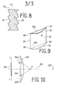
- FIG. 8 shows a Fresnel lens 80, with useful flanks 81 and 82, and a mask 83. If the Fresnel lens has symmetry of revolution, the mask can also have this same symmetry, and be composed of a set of opaque crowns, located in a plane perpendicular to the axis of the lens 80.
- Two useful flanks such as the flanks 41 and 42 of FIG. 4 behave like a prism.
- a first way to achieve this is to use the connecting flanks, giving them an angle of inclination such that there is total reflection of the light having penetrated into the material via a useful flank.
- FIG. 7 There is a Fresnel lens 70, useful flanks 71 and 74, connecting flanks 72 and 73.
- the sides 72 have a variable angle of inclination.
- the flank 73 has an angle of inclination such that the light entering said lens via the useful flank 74 undergoes on the flank 73 a total reflection. There will therefore be here a refraction on the flank 74, followed by a reflection inside the lens, on the flank 73.
- On the side on the observer side it is possible, in the same way, to have connecting flanks 75 causing total reflection inside the lens; before passing via the useful output flank 76.
- the combination of the two successive total reflections makes it possible to produce a deflection of the light, this deviation coming to combine with the deviations caused by the useful flanks of entry and exit.
- FIG. 9 there can be seen, in perspective view, a lens 90 (thick or Fresnel) of rectangular overall shape, with two vertical edges 91 and 92, and two horizontal edges 93 and 94.
- a bar 95a joining the two upper corners 96 and 97 of the lens 90.
- Another bar 95b can also be arranged between the lower corners 98 and 99 of the lens 90.
- the modification of the optical effect can be used to enlarge the image preferably in the horizontal direction, for example, or to correct certain deformations of the lens. virtual image produced by the lens.
- said lens can be made from a material which is flexible enough to allow said lens, at least locally, to have a curvature. This flexibility will wrap the lens around an axis, to reduce its bulk when not in use.
Landscapes
- Physics & Mathematics (AREA)
- General Physics & Mathematics (AREA)
- Optics & Photonics (AREA)
- Lenses (AREA)
- Devices For Indicating Variable Information By Combining Individual Elements (AREA)
- Medicines That Contain Protein Lipid Enzymes And Other Medicines (AREA)
Applications Claiming Priority (3)
| Application Number | Priority Date | Filing Date | Title |
|---|---|---|---|
| FR8909371A FR2649799B1 (fr) | 1989-07-12 | 1989-07-12 | Systeme optique pour l'agrandissement d'images |
| FR8909371 | 1989-07-12 | ||
| US07/551,529 US5583702A (en) | 1989-07-12 | 1990-07-11 | Optical system for enlarging images |
Publications (2)
| Publication Number | Publication Date |
|---|---|
| EP0408445A1 true EP0408445A1 (de) | 1991-01-16 |
| EP0408445B1 EP0408445B1 (de) | 1996-02-28 |
Family
ID=26227468
Family Applications (1)
| Application Number | Title | Priority Date | Filing Date |
|---|---|---|---|
| EP90401990A Expired - Lifetime EP0408445B1 (de) | 1989-07-12 | 1990-07-10 | Optische Vorrichtung zur Bildvergrösserung |
Country Status (6)
| Country | Link |
|---|---|
| US (1) | US5583702A (de) |
| EP (1) | EP0408445B1 (de) |
| JP (1) | JPH03136016A (de) |
| CA (1) | CA2020819A1 (de) |
| DE (1) | DE69025502T2 (de) |
| FR (1) | FR2649799B1 (de) |
Cited By (1)
| Publication number | Priority date | Publication date | Assignee | Title |
|---|---|---|---|---|
| GB2274727A (en) * | 1993-01-29 | 1994-08-03 | Virtuality Entertainment Ltd | Optical display system |
Families Citing this family (30)
| Publication number | Priority date | Publication date | Assignee | Title |
|---|---|---|---|---|
| DE4228962C2 (de) * | 1991-08-30 | 1996-08-14 | Kansei Kk | Optisches System zum Vergrößern eines Anzeigefeldes |
| USD398316S (en) | 1997-08-18 | 1998-09-15 | Thomas Feldman | Magnifying device for the display of a videocassette recorder or stereo |
| US6002524A (en) * | 1997-09-29 | 1999-12-14 | Imation Corp. | Flexible lens |
| US6108025A (en) * | 1997-09-29 | 2000-08-22 | Eastman Kodak Company | Optical scanner system having a laser beam power attentuation mechanism |
| US6057537A (en) * | 1997-09-29 | 2000-05-02 | Eastman Kodak Company | Optical scanner feedback system having a reflected cylinder lens |
| US5932151A (en) * | 1997-09-29 | 1999-08-03 | Imation Corp. | Method of making a flexible lens |
| US6094287A (en) * | 1998-12-03 | 2000-07-25 | Eastman Kodak Company | Wobble correcting monogon scanner for a laser imaging system |
| DE19932592A1 (de) * | 1999-07-13 | 2001-01-18 | Lissotschenko Vitalij | Abbildungssystem |
| US20050095407A1 (en) * | 2003-11-04 | 2005-05-05 | Coburn Joseph W.Jr. | Spaced-apart fresnel lens decorative material and process of manufacturing the material |
| JP4365435B2 (ja) * | 2007-10-12 | 2009-11-18 | リアルヴュー イノべイションズ リミテッド | 奥行き強調スクリーン |
| TWI357481B (en) * | 2008-12-05 | 2012-02-01 | Ind Tech Res Inst | A light source module for producing polarized ligh |
| DE102009049167A1 (de) * | 2009-10-12 | 2011-05-05 | Imos Gubela Gmbh | Sicherheitslupe zur Vergrößerung und zur Vermeidung des Brennglaseffektes |
| US20110299168A1 (en) * | 2010-06-04 | 2011-12-08 | Combs Jeffrey S | Display Screen Covers Having Personalized Refractive Power Capabilities |
| US9778829B2 (en) | 2012-02-17 | 2017-10-03 | Lenovo (Singapore) Pte. Ltd. | Magnification based on eye input |
| US10163455B2 (en) | 2013-12-03 | 2018-12-25 | Lenovo (Singapore) Pte. Ltd. | Detecting pause in audible input to device |
| US9110635B2 (en) | 2013-12-03 | 2015-08-18 | Lenova (Singapore) Pte. Ltd. | Initiating personal assistant application based on eye tracking and gestures |
| US9213659B2 (en) | 2013-12-03 | 2015-12-15 | Lenovo (Singapore) Pte. Ltd. | Devices and methods to receive input at a first device and present output in response on a second device different from the first device |
| US9709708B2 (en) | 2013-12-09 | 2017-07-18 | Lenovo (Singapore) Pte. Ltd. | Adjustable display optics |
| US10180716B2 (en) | 2013-12-20 | 2019-01-15 | Lenovo (Singapore) Pte Ltd | Providing last known browsing location cue using movement-oriented biometric data |
| US9633252B2 (en) | 2013-12-20 | 2017-04-25 | Lenovo (Singapore) Pte. Ltd. | Real-time detection of user intention based on kinematics analysis of movement-oriented biometric data |
| US10073671B2 (en) | 2014-01-20 | 2018-09-11 | Lenovo (Singapore) Pte. Ltd. | Detecting noise or object interruption in audio video viewing and altering presentation based thereon |
| US9811095B2 (en) | 2014-08-06 | 2017-11-07 | Lenovo (Singapore) Pte. Ltd. | Glasses with fluid-fillable membrane for adjusting focal length of one or more lenses of the glasses |
| US9535497B2 (en) | 2014-11-20 | 2017-01-03 | Lenovo (Singapore) Pte. Ltd. | Presentation of data on an at least partially transparent display based on user focus |
| US10013540B2 (en) | 2015-03-10 | 2018-07-03 | Lenovo (Singapore) Pte. Ltd. | Authentication based on body movement |
| US10860094B2 (en) | 2015-03-10 | 2020-12-08 | Lenovo (Singapore) Pte. Ltd. | Execution of function based on location of display at which a user is looking and manipulation of an input device |
| US10499164B2 (en) | 2015-03-18 | 2019-12-03 | Lenovo (Singapore) Pte. Ltd. | Presentation of audio based on source |
| US10621431B2 (en) | 2015-03-27 | 2020-04-14 | Lenovo (Singapore) Pte. Ltd. | Camera that uses light from plural light sources disposed on a device |
| US20190094520A1 (en) * | 2017-03-24 | 2019-03-28 | Carrill D. Kelly | Vision correction device for a display |
| CN109901252B (zh) * | 2017-12-07 | 2020-04-14 | 京东方科技集团股份有限公司 | 一种光学透镜、眼镜及显示装置 |
| US10955988B1 (en) | 2020-02-14 | 2021-03-23 | Lenovo (Singapore) Pte. Ltd. | Execution of function based on user looking at one area of display while touching another area of display |
Citations (7)
| Publication number | Priority date | Publication date | Assignee | Title |
|---|---|---|---|---|
| GB902535A (en) * | 1959-04-06 | 1962-08-01 | James A Jobling And Company Lt | Improvements in or relating to lenses |
| US3447860A (en) * | 1967-07-03 | 1969-06-03 | James W Lucas | Large aperture achromat objective |
| DE2210727A1 (de) * | 1971-03-05 | 1972-09-14 | Hitachi Ltd | Korrekturhnse zur Verwendung bei der Herstellung einer fluoreszierenden Schicht einer Farbfernsehbildrohre |
| US3936151A (en) * | 1972-12-04 | 1976-02-03 | Hitachi, Ltd. | Correction lenses utilized to form fluorescent screens of colour picture tubes |
| US3980399A (en) * | 1971-11-25 | 1976-09-14 | U.S. Philips Corporation | Aspheric optical elements |
| FR2472197A1 (fr) * | 1979-12-18 | 1981-06-26 | Cintra Daniel | Lentille de fresnel et son application a la television |
| US4423438A (en) * | 1981-02-26 | 1983-12-27 | Nec Kansai, Ltd. | Projection type cathode ray tube with masking means |
Family Cites Families (4)
| Publication number | Priority date | Publication date | Assignee | Title |
|---|---|---|---|---|
| US2683394A (en) * | 1951-09-08 | 1954-07-13 | American Optical Corp | Wide aperture optical projection lens system |
| FR1346696A (fr) * | 1963-02-06 | 1963-12-20 | écran auxiliaire pour appareil de télévision | |
| FR1379018A (fr) * | 1963-10-08 | 1964-11-20 | Support pour dispositif grossissant d'images télévisées | |
| US3523721A (en) * | 1968-12-09 | 1970-08-11 | Zeiss Jena Veb Carl | Spherically corrected fresnel lenses and mirrors with partial field correction |
-
1989
- 1989-07-12 FR FR8909371A patent/FR2649799B1/fr not_active Expired - Fee Related
-
1990
- 1990-07-10 EP EP90401990A patent/EP0408445B1/de not_active Expired - Lifetime
- 1990-07-10 CA CA002020819A patent/CA2020819A1/fr not_active Abandoned
- 1990-07-10 DE DE69025502T patent/DE69025502T2/de not_active Expired - Fee Related
- 1990-07-11 US US07/551,529 patent/US5583702A/en not_active Expired - Fee Related
- 1990-07-12 JP JP2182849A patent/JPH03136016A/ja active Pending
Patent Citations (7)
| Publication number | Priority date | Publication date | Assignee | Title |
|---|---|---|---|---|
| GB902535A (en) * | 1959-04-06 | 1962-08-01 | James A Jobling And Company Lt | Improvements in or relating to lenses |
| US3447860A (en) * | 1967-07-03 | 1969-06-03 | James W Lucas | Large aperture achromat objective |
| DE2210727A1 (de) * | 1971-03-05 | 1972-09-14 | Hitachi Ltd | Korrekturhnse zur Verwendung bei der Herstellung einer fluoreszierenden Schicht einer Farbfernsehbildrohre |
| US3980399A (en) * | 1971-11-25 | 1976-09-14 | U.S. Philips Corporation | Aspheric optical elements |
| US3936151A (en) * | 1972-12-04 | 1976-02-03 | Hitachi, Ltd. | Correction lenses utilized to form fluorescent screens of colour picture tubes |
| FR2472197A1 (fr) * | 1979-12-18 | 1981-06-26 | Cintra Daniel | Lentille de fresnel et son application a la television |
| US4423438A (en) * | 1981-02-26 | 1983-12-27 | Nec Kansai, Ltd. | Projection type cathode ray tube with masking means |
Cited By (2)
| Publication number | Priority date | Publication date | Assignee | Title |
|---|---|---|---|---|
| GB2274727A (en) * | 1993-01-29 | 1994-08-03 | Virtuality Entertainment Ltd | Optical display system |
| GB2274727B (en) * | 1993-01-29 | 1996-06-12 | Virtuality Entertainment Ltd | Optical system |
Also Published As
| Publication number | Publication date |
|---|---|
| DE69025502T2 (de) | 1996-10-31 |
| DE69025502D1 (de) | 1996-04-04 |
| JPH03136016A (ja) | 1991-06-10 |
| US5583702A (en) | 1996-12-10 |
| CA2020819A1 (fr) | 1991-01-13 |
| EP0408445B1 (de) | 1996-02-28 |
| FR2649799B1 (fr) | 1993-05-28 |
| FR2649799A1 (fr) | 1991-01-18 |
Similar Documents
| Publication | Publication Date | Title |
|---|---|---|
| EP0408445B1 (de) | Optische Vorrichtung zur Bildvergrösserung | |
| JP2916063B2 (ja) | テーパ状多層照明装置 | |
| DE69728754T2 (de) | Gerät zur rückseitigen beleuchtung einer flüssigkristallanzeigevorrichtung | |
| US20020196980A1 (en) | Combined wavefront coding and amplitude contrast imaging systems | |
| EP0487385B1 (de) | Kollimierte Anzeigvorrichtung mit einem aussen, axialen, sphärischen Spiegel für einen Simulator | |
| WO2009121810A1 (fr) | Lunettes informatives | |
| WO1998020390A1 (fr) | Dispositif de visualisation et ecran plat de television utilisant ce dispositif | |
| KR20010108062A (ko) | 대각선 비틀림을 정정하기 위한 백라이트 | |
| EP3574301A1 (de) | Optischer detektor von partikeln | |
| EP4052073B1 (de) | Diffraktives optisches element mit einer metaoberfläche für die tirf-mikroskopie | |
| TW202232139A (zh) | 包括光吸收光學諧振腔之光學構造及光學系統 | |
| FR2627292A1 (fr) | Systeme optique a diaphragme de zone partielle | |
| EP0121962B1 (de) | Vorrichtung zur optischen Kopplung zwischen Lichtwellenleitern | |
| WO2015040288A1 (fr) | Dispositif catadioptrique améliorant la visualisation d'une image placée devant un capteur solaire | |
| EP4543617B1 (de) | Optische vorrichtung zum abtasten eines lichtstrahls über ein zu bearbeitendes werkstück | |
| EP3583402B1 (de) | Optischer partikeldetektor und verfahren zur herstellung eines optischen partikeldetektor | |
| EP4284625B1 (de) | Nanostrukturierte oberflächenbeschichtung zur erzeugung neuartiger visueller erscheinungen | |
| EP0738077B1 (de) | Kompakter Rückprojektionsvideomonitor bzw. -fernseher | |
| FR2472197A1 (fr) | Lentille de fresnel et son application a la television | |
| EP0553583A1 (de) | Infrarotkamera mit selbsttemperaturkompensiertem optischem System | |
| CN212569191U (zh) | 一种透射式体全息光栅 | |
| EP3660559B1 (de) | Fertigungsverfahren eines optischen kopplers | |
| JP2002277963A (ja) | 背面投写スクリーン | |
| EP3365718A1 (de) | Optisches system für thermischen bildgeber | |
| FR3144664A1 (fr) | Dispositif d’observation d’un échantillon par imagerie |
Legal Events
| Date | Code | Title | Description |
|---|---|---|---|
| PUAI | Public reference made under article 153(3) epc to a published international application that has entered the european phase |
Free format text: ORIGINAL CODE: 0009012 |
|
| AK | Designated contracting states |
Kind code of ref document: A1 Designated state(s): BE CH DE ES FR GB IT LI NL SE |
|
| 17P | Request for examination filed |
Effective date: 19910710 |
|
| 17Q | First examination report despatched |
Effective date: 19930721 |
|
| GRAA | (expected) grant |
Free format text: ORIGINAL CODE: 0009210 |
|
| AK | Designated contracting states |
Kind code of ref document: B1 Designated state(s): BE CH DE ES FR GB IT LI NL SE |
|
| PG25 | Lapsed in a contracting state [announced via postgrant information from national office to epo] |
Ref country code: IT Free format text: LAPSE BECAUSE OF FAILURE TO SUBMIT A TRANSLATION OF THE DESCRIPTION OR TO PAY THE FEE WITHIN THE PRE;WARNING: LAPSES OF ITALIAN PATENTS WITH EFFECTIVE DATE BEFORE 2007 MAY HAVE OCCURRED AT ANY TIME BEFORE 2007. THE CORRECT EFFECTIVE DATE MAY BE DIFFERENT FROM THE ONE RECORDED.SCRIBED TIME-LIMIT Effective date: 19960228 Ref country code: NL Free format text: LAPSE BECAUSE OF FAILURE TO SUBMIT A TRANSLATION OF THE DESCRIPTION OR TO PAY THE FEE WITHIN THE PRESCRIBED TIME-LIMIT Effective date: 19960228 Ref country code: ES Free format text: THE PATENT HAS BEEN ANNULLED BY A DECISION OF A NATIONAL AUTHORITY Effective date: 19960228 |
|
| REF | Corresponds to: |
Ref document number: 69025502 Country of ref document: DE Date of ref document: 19960404 |
|
| PG25 | Lapsed in a contracting state [announced via postgrant information from national office to epo] |
Ref country code: SE Effective date: 19960531 |
|
| GBT | Gb: translation of ep patent filed (gb section 77(6)(a)/1977) |
Effective date: 19960530 |
|
| PG25 | Lapsed in a contracting state [announced via postgrant information from national office to epo] |
Ref country code: CH Effective date: 19960731 Ref country code: BE Effective date: 19960731 Ref country code: LI Effective date: 19960731 |
|
| NLV1 | Nl: lapsed or annulled due to failure to fulfill the requirements of art. 29p and 29m of the patents act | ||
| PLBE | No opposition filed within time limit |
Free format text: ORIGINAL CODE: 0009261 |
|
| STAA | Information on the status of an ep patent application or granted ep patent |
Free format text: STATUS: NO OPPOSITION FILED WITHIN TIME LIMIT |
|
| BERE | Be: lapsed |
Owner name: CINTRA DANIEL Effective date: 19960731 |
|
| 26N | No opposition filed | ||
| REG | Reference to a national code |
Ref country code: CH Ref legal event code: PL |
|
| PGFP | Annual fee paid to national office [announced via postgrant information from national office to epo] |
Ref country code: GB Payment date: 19971223 Year of fee payment: 8 |
|
| PGFP | Annual fee paid to national office [announced via postgrant information from national office to epo] |
Ref country code: FR Payment date: 19980120 Year of fee payment: 8 |
|
| PGFP | Annual fee paid to national office [announced via postgrant information from national office to epo] |
Ref country code: DE Payment date: 19980124 Year of fee payment: 8 |
|
| PG25 | Lapsed in a contracting state [announced via postgrant information from national office to epo] |
Ref country code: GB Free format text: LAPSE BECAUSE OF NON-PAYMENT OF DUE FEES Effective date: 19980710 |
|
| GBPC | Gb: european patent ceased through non-payment of renewal fee |
Effective date: 19980710 |
|
| PG25 | Lapsed in a contracting state [announced via postgrant information from national office to epo] |
Ref country code: FR Free format text: LAPSE BECAUSE OF NON-PAYMENT OF DUE FEES Effective date: 19990331 |
|
| PG25 | Lapsed in a contracting state [announced via postgrant information from national office to epo] |
Ref country code: DE Free format text: LAPSE BECAUSE OF NON-PAYMENT OF DUE FEES Effective date: 19990501 |
|
| REG | Reference to a national code |
Ref country code: FR Ref legal event code: ST |