EP0408445B1 - Optische Vorrichtung zur Bildvergrösserung - Google Patents
Optische Vorrichtung zur Bildvergrösserung Download PDFInfo
- Publication number
- EP0408445B1 EP0408445B1 EP90401990A EP90401990A EP0408445B1 EP 0408445 B1 EP0408445 B1 EP 0408445B1 EP 90401990 A EP90401990 A EP 90401990A EP 90401990 A EP90401990 A EP 90401990A EP 0408445 B1 EP0408445 B1 EP 0408445B1
- Authority
- EP
- European Patent Office
- Prior art keywords
- lens
- flanks
- image
- source image
- distance
- Prior art date
- Legal status (The legal status is an assumption and is not a legal conclusion. Google has not performed a legal analysis and makes no representation as to the accuracy of the status listed.)
- Expired - Lifetime
Links
- 230000003287 optical effect Effects 0.000 title claims description 22
- 230000006870 function Effects 0.000 claims description 28
- 230000003247 decreasing effect Effects 0.000 claims description 9
- 238000005520 cutting process Methods 0.000 claims description 5
- 230000002093 peripheral effect Effects 0.000 claims description 5
- 238000000034 method Methods 0.000 description 12
- 230000000694 effects Effects 0.000 description 7
- 229920000297 Rayon Polymers 0.000 description 6
- 239000002964 rayon Substances 0.000 description 6
- 239000000463 material Substances 0.000 description 5
- 239000012780 transparent material Substances 0.000 description 5
- 238000000151 deposition Methods 0.000 description 2
- 238000005304 joining Methods 0.000 description 2
- 239000004973 liquid crystal related substance Substances 0.000 description 2
- 230000004048 modification Effects 0.000 description 2
- 238000012986 modification Methods 0.000 description 2
- 229920003229 poly(methyl methacrylate) Polymers 0.000 description 2
- 239000004926 polymethyl methacrylate Substances 0.000 description 2
- 230000005855 radiation Effects 0.000 description 2
- 238000007650 screen-printing Methods 0.000 description 2
- 239000000126 substance Substances 0.000 description 2
- 230000004075 alteration Effects 0.000 description 1
- 230000007423 decrease Effects 0.000 description 1
- 230000008021 deposition Effects 0.000 description 1
- 238000006073 displacement reaction Methods 0.000 description 1
- 238000010438 heat treatment Methods 0.000 description 1
- 238000004519 manufacturing process Methods 0.000 description 1
- 230000008569 process Effects 0.000 description 1
- 229910001285 shape-memory alloy Inorganic materials 0.000 description 1
- 238000000904 thermoluminescence Methods 0.000 description 1
- 238000002834 transmittance Methods 0.000 description 1
Images


Classifications
-
- G—PHYSICS
- G02—OPTICS
- G02B—OPTICAL ELEMENTS, SYSTEMS OR APPARATUS
- G02B27/00—Optical systems or apparatus not provided for by any of the groups G02B1/00 - G02B26/00, G02B30/00
- G02B27/02—Viewing or reading apparatus
- G02B27/04—Viewing or reading apparatus having collapsible parts
-
- G—PHYSICS
- G02—OPTICS
- G02B—OPTICAL ELEMENTS, SYSTEMS OR APPARATUS
- G02B3/00—Simple or compound lenses
- G02B3/02—Simple or compound lenses with non-spherical faces
Definitions
- the present invention relates to the enlargement of images, such as those produced by television apparatus.
- An optical system such as an assembly comprising at least one thick lens or its equivalent is used for this purpose, which makes it possible to obtain, from a real object, an enlarged image, with the possibility, for an observer, of move in a fairly large area while observing a correct image, that is to say without annoying deformation.
- image generator will mean any system producing an image, such as cathode ray tube, liquid crystal screen, plasma screen, by thermoluminescence, hologram generator or any other means producing images with 2 or 3 dimensions.
- the image produced by the image generator will be called "source image”; for example, if the image generator is a cathode ray tube, the source image is carried by the screen of said tube.
- the line perpendicular to the source image at its center will be called the "axis" of the source image.
- the straight intersection of these two planes will be called “axis” of the source image, and the intersection of said image will be called “center” of the source image. with the axis of said image.
- thick lens a piece of transparent material, generally having the shape of a disc or a rectangle, and limited on each of its two faces by a surface. Said thick lens does not necessarily have a symmetry of revolution, and does not necessarily have a plane of symmetry.
- An embodiment of a thick lens will be called a "Fresnel lens", said embodiment using the step technique on at least part of said Fresnel lens.
- the straight line perpendicular to said lens at its center will be called the "axis" of a lens.
- optically useful part a part of a thick lens or Fresnel through which light rays enter or leave participating in the achievement of the enlargement effect of the source image.
- Fresnel surface One of the two stepped surfaces of a Fresnel lens will be called a "Fresnel surface”.
- Useful flank on a Fresnel surface, a flank through which light rays enter or exit participating in the realization of the enlargement effect of the source image.
- connecting flank on a Fresnel surface, a flank through which light rays come in or out that do not participate in the effect of enlarging the source image.
- Two successive useful flanks are connected together by zero (case where two successive useful flanks have a common point), one or more connecting flanks.
- cylindrical lens a thick or Fresnel lens generated by a closed plane surface moving along a line segment.
- observation area The area where the observer can be located to observe a correct image
- observation area is a cone having the axis of the lens as its axis, and the center of the face of the lens on the observer side as its apex.
- the observation area will be characterized by the "opening" of the system, which is the half-angle at the top of said cone.
- US-A-3,936,151 describes a optical system comprising a lens having a convex face in the center and concave at the periphery; produced using a technique with non-circular steps, and a flat face. The light source is punctual.
- GB-A-902 535 describes a lens producing a beam of parallel rays exclusively from a point light source (focal point of the lens).
- US-A-4,423,438 describes a projection system for television images, producing a real image. We use a Schmidt lens to correct a spherical aberration. This lens has a flat face.
- US-A-3 980 399 describes a method of manufacturing a lens having a convex profile in the center and concave at the periphery on the two faces of the lens.
- FR-A-1 346 696 FR-A-1 379 018, FR-A-2 472 197 and in US-A-3 418 426.
- a Fresnel lens is used to produce an enlarged virtual image of a source image which may consist of a television screen.
- FR-A-2 472 197 describes a Fresnel lens simulating a thick lens of revolution, the side of the source image side of which is concave in the central region of said thick lens, and convex in the peripheral region, and the side of which is on the observer side everywhere convex.
- document US-A-2 683 394 describes an optical system comprising the structural elements of the preamble of the first claim, but the operation and purpose of which are extremely different from those of the system according to the invention.
- the optical system according to this document comprises both lenses acting by refringence and mirrors. The latter, pressed against the transparent material, act according to the laws of reflection and not according to those of refraction.
- this optical system finds its application as a projection system producing a virtual image, the source image being located between the virtual image and the optical system.
- the present invention which relates to the enlargement of images such as those produced by television sets, is clearly defined by the characterizing part of the main claim.
- Other aspects of the invention are the subject of the subclaims.
- Figure 1 is a sectional view of the system according to the present invention, in which the optical part is a thick lens, which can be made of a substance such as polymethyl methacrylate.
- Figure 2 is a perspective view of the system according to the present invention, in which the optical part is a pair of thick cylindrical lenses.
- FIG. 3 is a perspective view of the system according to the present invention, in which the optical part is a Fresnel lens, which can be produced in a substance such as polymethyl methacrylate.
- Figure 4 is a partial sectional view of the lens of Figure 3, said view specifying parameters for the quantitative definition of a preferred embodiment of the present invention.
- Figures 5, 6 and 8 are partial sectional views of Fresnel lenses according to the present invention, illustrating means for reducing the stray rays transmitted by said lenses.
- Figure 7 is a partial sectional view of a Fresnel lens according to the present invention, illustrating means for modifying the deflection characteristics of the light rays by said lens.
- Figure 9 is a perspective view of a lens (thick or Fresnel) according to the present invention, provided with a device for deforming said lens.
- Figure 10 is a sectional view for clarifying the importance of the convex region of one of the faces of the optical system according to the present invention.
- FIG. 1 an embodiment of the present invention is seen, in section, seen from above: distinguishes the source image 10, a thick lens 12 and the observer 13.
- the source image 10 has an axis 11.
- the section plane is parallel to the axis 11. In the in this case, it contains the axis 11.
- the intersection curve of the thick lens and the section plane is convex in the central part 14, and concave in the peripheral part 15.
- curve 16 intersection of said lens and the section plane is everywhere convex, and strictly convex on at least part of said curve.
- the lens 12 does not necessarily have symmetry of revolution.
- the points M and N are located in the section plane, and are located at the same distance u from said axis.
- the distance from M to N is a decreasing function of the distance u.
- a particular case of said variant is that where the lens 12 has a symmetry of revolution with respect to the axis 11.
- FIG. 2 we see another embodiment of the present invention, shown in perspective.
- a source image 20 and its axis 21 a first thick cylindrical lens 22, of vertical generator, a second thick cylindrical lens 23, of horizontal generator, and an observer 24.
- the base surfaces of the cylinders have the same properties as the sectional view of the lens 12 in FIG. 1.
- a variant of this embodiment based on cylindrical lenses consists of lenses of a cylindrical nature, but in which the shape of the base surface varies slightly as a function of the displacement along the generator.
- a source image 30 and its axis 31 are distinguished, a Fresnel lens 32 according to the present invention, and the observer 33.
- the lens 32 admits an axis which is also the axis 31 of the image source.
- the lens 32 could admit only a vertical plane of symmetry containing the axis 31 of the source image.
- the lens 32 could have an axis distinct from the axis of the source image, but preferably parallel to the latter.
- Figure 4 is a partial sectional view of the lens 32 of Figure 3, section along a vertical plane containing the axis 31.
- the Fresnel lens 40 and its axis 43 there are: the Fresnel lens 40 and its axis 43; an active side 41 and a connecting side 44, located on the source side; an active side 42 and a connecting side 45, located on the observer side; the ends F and J of the flank 41, F being further from the axis 43 than J; the ends H and K of the sidewall 42, H being further from the axis 43 than K; the end G of the flank 44, G being closer to the axis 43 than J; the end I of the flank 45, I being closer to the axis 43 than J; an Oxz coordinate system, O being above the axis 43, Oz being parallel to the axis 43 and pointing towards the observer, Ox being perpendicular to the axis 43 and pointing towards the axis 43.
- b and d the angles defining the connecting flanks such as 44 and 45.
- b ( Ox ⁇ , JG ⁇ )
- d ( Ox ⁇ , KI ⁇ ).
- groove the set consisting of two contiguous flanks such as FJ and JG, joining in a valley.
- the distance between two successive ridges such as F and G will be called the "width" of a groove.
- the grooves generally have a constant width on one face of a Fresnel lens. However, it is also possible to provide grooves of variable width.
- radius of flatness in a cutting plane such as that of FIG. 4, the distance between the axis and the first useful flank (starting from axis 43) having a zero angle of inclination, said flank not being that located on axis 43.
- the radius of flatness is not equal to the radius of inflection.
- the functions giving the angles of inclination of the useful flanks 41 and 42 as a function of the distance from said flanks to the axis 43 of the Fresnel lens are such that, at any point of said lens, the function giving the inclination angle of the useful flank 42 on the observer side has a value greater than that of the function giving the inclination angle of the useful flank 41 on the source image side.
- the useful flanks and the connecting flanks alternate.
- a useful flank 46 on the source image side and a useful flank 47 on the observer side.
- FIG. 5 There is a Fresnel lens 50 there with useful flanks 51 and 52, and with connecting flanks 53 and 54. One can opacify the connecting flanks on the two faces or on a single face, or on certain regions of at least one of the two faces.
- the sides of FIG. 5 can be clouded by deposition, screen printing, projection or by cathodic process.
- Figure 6 shows a different arrangement of the sides.
- a Fresnel lens 60 useful flanks 61 and 64, connecting flanks 62 and 63.
- the sidewall 62 has a variable angle of inclination.
- the sidewall 63 has a zero tilt angle. This makes it possible to easily opacify the flanks such as the flank 63, using a simple screen printing marking, for example.
- FIG. 8 shows a Fresnel lens 80, with useful flanks 81 and 82, and a mask 83. If the Fresnel lens has symmetry of revolution, the mask can also have this same symmetry, and be composed of a set of opaque crowns, located in a plane perpendicular to the axis of the lens 80.
- Two useful flanks such as the flanks 41 and 42 of FIG. 4 behave like a prism.
- a first way to achieve this is to use the connecting flanks, giving them an angle of inclination such that there is total reflection of the light having penetrated into the material via a useful flank.
- FIG. 7 There is a Fresnel lens 70, useful flanks 71 and 74, connecting flanks 72 and 73.
- the sidewalls 72 have a variable angle of inclination.
- the flank 73 has an angle of inclination such that the light entering said lens via the useful flank 74 undergoes total reflection on the flank 73. There will therefore be here a refraction on the flank 74, followed by a reflection inside the lens, on the flank 73.
- On the side on the observer side it is possible, in the same way, to have connecting flanks 75 causing total reflection inside the lens, before passing via the useful output flank 76.
- the combination of the two successive total reflections allows to achieve a deflection of light, this deflection coming to combine with the deflections caused by the useful flanks of entry and exit.
- FIG. 9 there can be seen, in perspective view, a lens 90 (thick or Fresnel) of rectangular overall shape, with two vertical edges 91 and 92, and two horizontal edges 93 and 94.
- a bar 95a joining the two upper corners 96 and 97 of the lens 90.
- Another bar 95b can also be arranged between the lower corners 98 and 99 of the lens 90.
- the modification of the optical effect can be used to enlarge the image preferentially in the horizontal direction, for example, or to correct certain deformations of the lens. virtual image produced by the lens.
- FIG. 10 are shown schematically, seen in section, a source image 100 and its axis 101, a point P of the axis 101, and a lens 102 according to the present invention, placed between the source image 100 and the point P. There is also an observer 105. The point P is located between the observer 105 and the source image.
- the cutting plane is, according to the present invention (see the description of FIG. 1), parallel to the axis of the source image and such that, on the side of the source image 100, the face of the lens 102a with the section plane an intersection which is a curve in which a central region 104 is convex and in which a peripheral region 103a and 103b is concave.
- a line segment ST located in the section plane of Figure 10; said line segment is perpendicular to the axis 101 of the source image 100; said line segment has the center of the source image 100 as its center, and the diagonal of the source image 100 as its length.
- FIG. 10 are also represented the points Q and R which constitute the border between the central region 104 and the peripheral region 103.
- the angle at which P sees said central region is the angle (PQ, PR).
- the angle at which P sees the ST segment is the angle (PS, PT).
- half the length QR will be called "inflection radius".
- z be the distance from P to said source image.
- z 0.0164 k-0.0298 ⁇ 2 + 1.206-0.7k ⁇ +7.334 k-11.042 D 0.70 with the notations and conventions defined above with respect to the first preferred embodiment of the present invention. Under these conditions, tests have shown that the tangent of the angle ⁇ is of the order of: tg ⁇ ⁇ 0.6k - 0.555 z D 0.70
- tg ⁇ D 2 z that is to say that we have: tg ⁇ ⁇ 0.6k-0.555 0.35 tg ⁇
- said lens can be made from a material which is sufficiently flexible to allow said lens to be given, at least locally, a curvature. This flexibility will wrap the lens around an axis, in order to reduce its size when it is not used.
Landscapes
- Physics & Mathematics (AREA)
- General Physics & Mathematics (AREA)
- Optics & Photonics (AREA)
- Lenses (AREA)
- Devices For Indicating Variable Information By Combining Individual Elements (AREA)
- Medicines That Contain Protein Lipid Enzymes And Other Medicines (AREA)
Claims (6)
- Optische Vorrichtung zur Bildvergrößerung mit einem optischen System, das zwischen einerseits einem Quellenbild (10, 20, 100), das aus einer Vielzahl von Punkten zusammengesetzt ist und eine Beobachtungsachse (11; 21; 101) definiert, und andererseits einem Beobachtungspunkt (13; 24; 105) angeordnet ist, wobei das optische System mindestens eine dicke Linse (12; 22; 23; 102) umfaßt, die einerseits eine erste Ebene aufweist, die parallel zur Beobachtungsachse des Quellenbildes ist und das System derart schneidet, daß der Schnitt der Ebene und des Systems mindestens eine in ihrem inneren Teil (14; 104) konvexe und in ihrem äußeren Teil (15; 103a, 103b) konkave Krümmung aufweist, und die andererseits eine zweite Ebene aufweist, die parallel zur Beobachtungsachse des Quellenbildes ist und das System derart schneidet, daß der Schnitt der Ebene und des Systems mindestens eine zweite Krümmung (16) aufweist, die vollständig konvex und auf zumindest einem Teil der Krümmung streng konvex ist,
dadurch gekennzeichnet, daß in der ersten Ebene der Winkel β, der gleich dem halben Winkel ist, unter dem der innere Teil (QR) von einem Punkt (P) aus gesehen wird, der auf der Beobachtungsachse (101) des Quellenbildes (100) zwischen dem Quellenbild und dem Beobachtungspunkt (105) und in einem Abstand z von dem Quellenbild liegt, mit dem Winkel Γ verknüpft ist, der gleich dem halben Winkel ist, unter dem von dem Punkt (P) aus ein Geradensegment (ST) gesehen wird, das senkrecht zur Beobachtungsachse des Quellenbildes steht und dessen Zentrum mit dem Zentrum des Quellenbildes zusammenfällt und dessen Länge gleich der Diagonalen des Quellenbildes ist, wobei zwischen β und Γ folgende Beziehung besteht: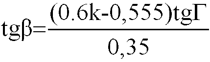
 k = effektive Vergrößerung des Systems,α = Öffnung des Systems in Grad,D = Diagonale des Quellenbildes in Metern.
 - Vorrichtung nach Anspruch 1, dadurch gekennzeichnet, daß der Abstand zwischen einem auf der ersten Krümmung (14, 15) gelegenen Punkt (M) und einem auf der zweiten Krümmung (16) in einem gleichen Abstand (u) von der Beobachtungsachse des Quellenbildes gelegenen entsprechenden Punkt (N) eine fallende Funktion von dem Abstand (u) der Punkte auf der Achse ist.
- Vorrichtung nach Anspruch 1 oder 2, dadurch gekennzeichnet, daß bei mindestens einer der optischen Oberflächen, die einen Teil (32; 40; 50; 60; 70; 80) umfassen, der in einer Stufen- oder sogenannten Fresneltechnik ausgeführt ist, die Funktionen, die die Neigungswinkel der nutzbaren Flanken (41, 42) in Abhängigkeit von dem Abstand der Flanken zur Achse (43) der Fresnellinse darstellen, folgende Eigenschaften aufweisen:- für den nach der Fresneltechnik hergestellten Teil auf der quellenbildseitigen Fläche ist die die nutzbaren Flanken darstellende Funktion zunächst fallend, dann steigend;- für den nach der Fresneltechnik hergestellten Teil auf der beobachtungspunktseitigen Fläche ist die die nutzbaren Flanken darstellende Funktion steigend.
- Vorrichtung nach Anspruch 3, dadurch gekennzeichnet, daß die die Neigungswinkel der nutzbaren Flanken (41, 42) in Abhängigkeit von dem Abstand der Flanken zur Achse (43) zu der Fresnellinse angebenden Funktionen derart beschaffen sind, daß die den Neigungswinkel der beobachtungspunktseitigen nutzbaren Flanke (42) angebende Funktion an jedem Punkt der Linse einen Wert aufweist, der größer als derjenige der Funktion ist, die den Neigungswinkel der quellenbildseitigen nutzbaren Flanke (41) angibt.
- Vorrichtung nach Anspruch 3, dadurch gekennzeichnet, daß die die Neigungswinkel der Verbindungsflanken (44, 45) in Abhängigkeit von dem Abstand der Flanken zur Achse (43) der Fresnellinse angebenden Funktionen folgende Eigenschaften aufweisen:- für die Verbindungsflanken (44) der quellenbildseitigen Fläche ist die Funktion bis zu einem Abstand in der Größenordnung des Umkehrabstands fallend, dann steigend, mit einer Unstetigkeit für x = Stufenabstand;- für die Verbindungsflanken (45) der beobachtungspunktseitigen Fläche ist die Funktion bis zu einem Abstand in der Größenordnung des Umkehrabstands steigend, dann bis zu einem Abstand in der Größenordnung des dreifachen Umkehrabstands fallend, dann steigend.
- Vorrichtung nach einem der Ansprüche 3 bis 5, dadurch gekennzeichnet, daß sie eine Maske (83) umfaßt, die zwischen einer quellenbildseitig gelegenen Fresnelfläche (81) und einer beobachtungspunktseitig gelegenen Fresnelfläche (82) angeordnet ist.
Applications Claiming Priority (3)
| Application Number | Priority Date | Filing Date | Title |
|---|---|---|---|
| FR8909371A FR2649799B1 (fr) | 1989-07-12 | 1989-07-12 | Systeme optique pour l'agrandissement d'images |
| FR8909371 | 1989-07-12 | ||
| US07/551,529 US5583702A (en) | 1989-07-12 | 1990-07-11 | Optical system for enlarging images |
Publications (2)
| Publication Number | Publication Date |
|---|---|
| EP0408445A1 EP0408445A1 (de) | 1991-01-16 |
| EP0408445B1 true EP0408445B1 (de) | 1996-02-28 |
Family
ID=26227468
Family Applications (1)
| Application Number | Title | Priority Date | Filing Date |
|---|---|---|---|
| EP90401990A Expired - Lifetime EP0408445B1 (de) | 1989-07-12 | 1990-07-10 | Optische Vorrichtung zur Bildvergrösserung |
Country Status (6)
| Country | Link |
|---|---|
| US (1) | US5583702A (de) |
| EP (1) | EP0408445B1 (de) |
| JP (1) | JPH03136016A (de) |
| CA (1) | CA2020819A1 (de) |
| DE (1) | DE69025502T2 (de) |
| FR (1) | FR2649799B1 (de) |
Families Citing this family (31)
| Publication number | Priority date | Publication date | Assignee | Title |
|---|---|---|---|---|
| DE4228962C2 (de) * | 1991-08-30 | 1996-08-14 | Kansei Kk | Optisches System zum Vergrößern eines Anzeigefeldes |
| GB9301769D0 (en) * | 1993-01-29 | 1993-03-17 | Ind Limited W | Opticla system |
| USD398316S (en) | 1997-08-18 | 1998-09-15 | Thomas Feldman | Magnifying device for the display of a videocassette recorder or stereo |
| US6002524A (en) * | 1997-09-29 | 1999-12-14 | Imation Corp. | Flexible lens |
| US6108025A (en) * | 1997-09-29 | 2000-08-22 | Eastman Kodak Company | Optical scanner system having a laser beam power attentuation mechanism |
| US6057537A (en) * | 1997-09-29 | 2000-05-02 | Eastman Kodak Company | Optical scanner feedback system having a reflected cylinder lens |
| US5932151A (en) * | 1997-09-29 | 1999-08-03 | Imation Corp. | Method of making a flexible lens |
| US6094287A (en) * | 1998-12-03 | 2000-07-25 | Eastman Kodak Company | Wobble correcting monogon scanner for a laser imaging system |
| DE19932592A1 (de) * | 1999-07-13 | 2001-01-18 | Lissotschenko Vitalij | Abbildungssystem |
| US20050095407A1 (en) * | 2003-11-04 | 2005-05-05 | Coburn Joseph W.Jr. | Spaced-apart fresnel lens decorative material and process of manufacturing the material |
| JP4365435B2 (ja) * | 2007-10-12 | 2009-11-18 | リアルヴュー イノべイションズ リミテッド | 奥行き強調スクリーン |
| TWI357481B (en) * | 2008-12-05 | 2012-02-01 | Ind Tech Res Inst | A light source module for producing polarized ligh |
| DE102009049167A1 (de) * | 2009-10-12 | 2011-05-05 | Imos Gubela Gmbh | Sicherheitslupe zur Vergrößerung und zur Vermeidung des Brennglaseffektes |
| US20110299168A1 (en) * | 2010-06-04 | 2011-12-08 | Combs Jeffrey S | Display Screen Covers Having Personalized Refractive Power Capabilities |
| US9778829B2 (en) | 2012-02-17 | 2017-10-03 | Lenovo (Singapore) Pte. Ltd. | Magnification based on eye input |
| US10163455B2 (en) | 2013-12-03 | 2018-12-25 | Lenovo (Singapore) Pte. Ltd. | Detecting pause in audible input to device |
| US9110635B2 (en) | 2013-12-03 | 2015-08-18 | Lenova (Singapore) Pte. Ltd. | Initiating personal assistant application based on eye tracking and gestures |
| US9213659B2 (en) | 2013-12-03 | 2015-12-15 | Lenovo (Singapore) Pte. Ltd. | Devices and methods to receive input at a first device and present output in response on a second device different from the first device |
| US9709708B2 (en) | 2013-12-09 | 2017-07-18 | Lenovo (Singapore) Pte. Ltd. | Adjustable display optics |
| US10180716B2 (en) | 2013-12-20 | 2019-01-15 | Lenovo (Singapore) Pte Ltd | Providing last known browsing location cue using movement-oriented biometric data |
| US9633252B2 (en) | 2013-12-20 | 2017-04-25 | Lenovo (Singapore) Pte. Ltd. | Real-time detection of user intention based on kinematics analysis of movement-oriented biometric data |
| US10073671B2 (en) | 2014-01-20 | 2018-09-11 | Lenovo (Singapore) Pte. Ltd. | Detecting noise or object interruption in audio video viewing and altering presentation based thereon |
| US9811095B2 (en) | 2014-08-06 | 2017-11-07 | Lenovo (Singapore) Pte. Ltd. | Glasses with fluid-fillable membrane for adjusting focal length of one or more lenses of the glasses |
| US9535497B2 (en) | 2014-11-20 | 2017-01-03 | Lenovo (Singapore) Pte. Ltd. | Presentation of data on an at least partially transparent display based on user focus |
| US10013540B2 (en) | 2015-03-10 | 2018-07-03 | Lenovo (Singapore) Pte. Ltd. | Authentication based on body movement |
| US10860094B2 (en) | 2015-03-10 | 2020-12-08 | Lenovo (Singapore) Pte. Ltd. | Execution of function based on location of display at which a user is looking and manipulation of an input device |
| US10499164B2 (en) | 2015-03-18 | 2019-12-03 | Lenovo (Singapore) Pte. Ltd. | Presentation of audio based on source |
| US10621431B2 (en) | 2015-03-27 | 2020-04-14 | Lenovo (Singapore) Pte. Ltd. | Camera that uses light from plural light sources disposed on a device |
| US20190094520A1 (en) * | 2017-03-24 | 2019-03-28 | Carrill D. Kelly | Vision correction device for a display |
| CN109901252B (zh) * | 2017-12-07 | 2020-04-14 | 京东方科技集团股份有限公司 | 一种光学透镜、眼镜及显示装置 |
| US10955988B1 (en) | 2020-02-14 | 2021-03-23 | Lenovo (Singapore) Pte. Ltd. | Execution of function based on user looking at one area of display while touching another area of display |
Citations (1)
| Publication number | Priority date | Publication date | Assignee | Title |
|---|---|---|---|---|
| US2683394A (en) * | 1951-09-08 | 1954-07-13 | American Optical Corp | Wide aperture optical projection lens system |
Family Cites Families (9)
| Publication number | Priority date | Publication date | Assignee | Title |
|---|---|---|---|---|
| GB902535A (en) * | 1959-04-06 | 1962-08-01 | James A Jobling And Company Lt | Improvements in or relating to lenses |
| FR1346696A (fr) * | 1963-02-06 | 1963-12-20 | écran auxiliaire pour appareil de télévision | |
| FR1379018A (fr) * | 1963-10-08 | 1964-11-20 | Support pour dispositif grossissant d'images télévisées | |
| US3447860A (en) * | 1967-07-03 | 1969-06-03 | James W Lucas | Large aperture achromat objective |
| US3523721A (en) * | 1968-12-09 | 1970-08-11 | Zeiss Jena Veb Carl | Spherically corrected fresnel lenses and mirrors with partial field correction |
| GB1362380A (en) * | 1971-11-25 | 1974-08-07 | Mullard Ltd | Manufacture of optical elements |
| JPS4979255A (de) * | 1972-12-04 | 1974-07-31 | ||
| FR2472197A1 (fr) * | 1979-12-18 | 1981-06-26 | Cintra Daniel | Lentille de fresnel et son application a la television |
| US4423438A (en) * | 1981-02-26 | 1983-12-27 | Nec Kansai, Ltd. | Projection type cathode ray tube with masking means |
-
1989
- 1989-07-12 FR FR8909371A patent/FR2649799B1/fr not_active Expired - Fee Related
-
1990
- 1990-07-10 EP EP90401990A patent/EP0408445B1/de not_active Expired - Lifetime
- 1990-07-10 CA CA002020819A patent/CA2020819A1/fr not_active Abandoned
- 1990-07-10 DE DE69025502T patent/DE69025502T2/de not_active Expired - Fee Related
- 1990-07-11 US US07/551,529 patent/US5583702A/en not_active Expired - Fee Related
- 1990-07-12 JP JP2182849A patent/JPH03136016A/ja active Pending
Patent Citations (1)
| Publication number | Priority date | Publication date | Assignee | Title |
|---|---|---|---|---|
| US2683394A (en) * | 1951-09-08 | 1954-07-13 | American Optical Corp | Wide aperture optical projection lens system |
Also Published As
| Publication number | Publication date |
|---|---|
| DE69025502T2 (de) | 1996-10-31 |
| DE69025502D1 (de) | 1996-04-04 |
| JPH03136016A (ja) | 1991-06-10 |
| EP0408445A1 (de) | 1991-01-16 |
| US5583702A (en) | 1996-12-10 |
| CA2020819A1 (fr) | 1991-01-13 |
| FR2649799B1 (fr) | 1993-05-28 |
| FR2649799A1 (fr) | 1991-01-18 |
Similar Documents
| Publication | Publication Date | Title |
|---|---|---|
| EP0408445B1 (de) | Optische Vorrichtung zur Bildvergrösserung | |
| DE69728754T2 (de) | Gerät zur rückseitigen beleuchtung einer flüssigkristallanzeigevorrichtung | |
| EP0150779B1 (de) | Kontaktlinse zur Beobachtung und Behandlung des Auges mit Lichtbestrahlung | |
| EP0487385B1 (de) | Kollimierte Anzeigvorrichtung mit einem aussen, axialen, sphärischen Spiegel für einen Simulator | |
| US20020196980A1 (en) | Combined wavefront coding and amplitude contrast imaging systems | |
| EP0880724A1 (de) | Anzeigevorrichtung und flacher fernsehbildschirm, der diese vorrichtung benutzt | |
| WO2009121810A1 (fr) | Lunettes informatives | |
| EP3574301A1 (de) | Optischer detektor von partikeln | |
| EP3132312A1 (de) | System zur anzeige eines bildes auf einer windschutzscheibe | |
| EP4052073B1 (de) | Diffraktives optisches element mit einer metaoberfläche für die tirf-mikroskopie | |
| FR2627292A1 (fr) | Systeme optique a diaphragme de zone partielle | |
| FR2555767A1 (fr) | Telescope a miroir a image redressee | |
| EP0121962A2 (de) | Vorrichtung zur optischen Kopplung zwischen Lichtwellenleitern | |
| EP0459850B1 (de) | Head-up-Anzeige und Helm mit wenigstens einer derartigen Anzeige | |
| FR3011125A1 (fr) | Dispositif catadioptrique ameliorant la visualisation d'une image placee devant un capteur solaire | |
| EP4284625B1 (de) | Nanostrukturierte oberflächenbeschichtung zur erzeugung neuartiger visueller erscheinungen | |
| EP3583402B1 (de) | Optischer partikeldetektor und verfahren zur herstellung eines optischen partikeldetektor | |
| EP0738077B1 (de) | Kompakter Rückprojektionsvideomonitor bzw. -fernseher | |
| EP4543617A1 (de) | Optische vorrichtung zum abtasten eines lichtstrahls über ein zu bearbeitendes werkstück | |
| FR2628221A1 (fr) | Dispositif de formation d'une image d'une surface en relief, notamment une empreinte digitale | |
| FR2472197A1 (fr) | Lentille de fresnel et son application a la television | |
| EP0553583A1 (de) | Infrarotkamera mit selbsttemperaturkompensiertem optischem System | |
| CN212569191U (zh) | 一种透射式体全息光栅 | |
| FR2492541A1 (fr) | Concentrateur de rayonnement solaire et son procede de fabrication | |
| FR2549242A1 (fr) | Procede et dispositif optique de concentration d'une energie rayonnante sur un element recepteur, et application a la captation d'energie telle que l'energie solaire |
Legal Events
| Date | Code | Title | Description |
|---|---|---|---|
| PUAI | Public reference made under article 153(3) epc to a published international application that has entered the european phase |
Free format text: ORIGINAL CODE: 0009012 |
|
| AK | Designated contracting states |
Kind code of ref document: A1 Designated state(s): BE CH DE ES FR GB IT LI NL SE |
|
| 17P | Request for examination filed |
Effective date: 19910710 |
|
| 17Q | First examination report despatched |
Effective date: 19930721 |
|
| GRAA | (expected) grant |
Free format text: ORIGINAL CODE: 0009210 |
|
| AK | Designated contracting states |
Kind code of ref document: B1 Designated state(s): BE CH DE ES FR GB IT LI NL SE |
|
| PG25 | Lapsed in a contracting state [announced via postgrant information from national office to epo] |
Ref country code: IT Free format text: LAPSE BECAUSE OF FAILURE TO SUBMIT A TRANSLATION OF THE DESCRIPTION OR TO PAY THE FEE WITHIN THE PRE;WARNING: LAPSES OF ITALIAN PATENTS WITH EFFECTIVE DATE BEFORE 2007 MAY HAVE OCCURRED AT ANY TIME BEFORE 2007. THE CORRECT EFFECTIVE DATE MAY BE DIFFERENT FROM THE ONE RECORDED.SCRIBED TIME-LIMIT Effective date: 19960228 Ref country code: NL Free format text: LAPSE BECAUSE OF FAILURE TO SUBMIT A TRANSLATION OF THE DESCRIPTION OR TO PAY THE FEE WITHIN THE PRESCRIBED TIME-LIMIT Effective date: 19960228 Ref country code: ES Free format text: THE PATENT HAS BEEN ANNULLED BY A DECISION OF A NATIONAL AUTHORITY Effective date: 19960228 |
|
| REF | Corresponds to: |
Ref document number: 69025502 Country of ref document: DE Date of ref document: 19960404 |
|
| PG25 | Lapsed in a contracting state [announced via postgrant information from national office to epo] |
Ref country code: SE Effective date: 19960531 |
|
| GBT | Gb: translation of ep patent filed (gb section 77(6)(a)/1977) |
Effective date: 19960530 |
|
| PG25 | Lapsed in a contracting state [announced via postgrant information from national office to epo] |
Ref country code: CH Effective date: 19960731 Ref country code: BE Effective date: 19960731 Ref country code: LI Effective date: 19960731 |
|
| NLV1 | Nl: lapsed or annulled due to failure to fulfill the requirements of art. 29p and 29m of the patents act | ||
| PLBE | No opposition filed within time limit |
Free format text: ORIGINAL CODE: 0009261 |
|
| STAA | Information on the status of an ep patent application or granted ep patent |
Free format text: STATUS: NO OPPOSITION FILED WITHIN TIME LIMIT |
|
| BERE | Be: lapsed |
Owner name: CINTRA DANIEL Effective date: 19960731 |
|
| 26N | No opposition filed | ||
| REG | Reference to a national code |
Ref country code: CH Ref legal event code: PL |
|
| PGFP | Annual fee paid to national office [announced via postgrant information from national office to epo] |
Ref country code: GB Payment date: 19971223 Year of fee payment: 8 |
|
| PGFP | Annual fee paid to national office [announced via postgrant information from national office to epo] |
Ref country code: FR Payment date: 19980120 Year of fee payment: 8 |
|
| PGFP | Annual fee paid to national office [announced via postgrant information from national office to epo] |
Ref country code: DE Payment date: 19980124 Year of fee payment: 8 |
|
| PG25 | Lapsed in a contracting state [announced via postgrant information from national office to epo] |
Ref country code: GB Free format text: LAPSE BECAUSE OF NON-PAYMENT OF DUE FEES Effective date: 19980710 |
|
| GBPC | Gb: european patent ceased through non-payment of renewal fee |
Effective date: 19980710 |
|
| PG25 | Lapsed in a contracting state [announced via postgrant information from national office to epo] |
Ref country code: FR Free format text: LAPSE BECAUSE OF NON-PAYMENT OF DUE FEES Effective date: 19990331 |
|
| PG25 | Lapsed in a contracting state [announced via postgrant information from national office to epo] |
Ref country code: DE Free format text: LAPSE BECAUSE OF NON-PAYMENT OF DUE FEES Effective date: 19990501 |
|
| REG | Reference to a national code |
Ref country code: FR Ref legal event code: ST |