EP0407916A1 - Barrel with bung - Google Patents
Barrel with bung Download PDFInfo
- Publication number
- EP0407916A1 EP0407916A1 EP90112983A EP90112983A EP0407916A1 EP 0407916 A1 EP0407916 A1 EP 0407916A1 EP 90112983 A EP90112983 A EP 90112983A EP 90112983 A EP90112983 A EP 90112983A EP 0407916 A1 EP0407916 A1 EP 0407916A1
- Authority
- EP
- European Patent Office
- Prior art keywords
- bung
- outer ring
- barrel
- lid
- bungholes
- Prior art date
- Legal status (The legal status is an assumption and is not a legal conclusion. Google has not performed a legal analysis and makes no representation as to the accuracy of the status listed.)
- Granted
Links
Images
Classifications
-
- B—PERFORMING OPERATIONS; TRANSPORTING
- B65—CONVEYING; PACKING; STORING; HANDLING THIN OR FILAMENTARY MATERIAL
- B65D—CONTAINERS FOR STORAGE OR TRANSPORT OF ARTICLES OR MATERIALS, e.g. BAGS, BARRELS, BOTTLES, BOXES, CANS, CARTONS, CRATES, DRUMS, JARS, TANKS, HOPPERS, FORWARDING CONTAINERS; ACCESSORIES, CLOSURES, OR FITTINGS THEREFOR; PACKAGING ELEMENTS; PACKAGES
- B65D1/00—Containers having bodies formed in one piece, e.g. by casting metallic material, by moulding plastics, by blowing vitreous material, by throwing ceramic material, by moulding pulped fibrous material, by deep-drawing operations performed on sheet material
- B65D1/12—Cans, casks, barrels, or drums
- B65D1/14—Cans, casks, barrels, or drums characterised by shape
- B65D1/16—Cans, casks, barrels, or drums characterised by shape of curved cross-section, e.g. cylindrical
Definitions
- the invention relates to plastic sheet drums with a jacket part, a bottom and a lid with integrally molded bung.
- a bung is known with a device for residual emptying, which is formed by collecting shells formed on the inside of the lid around the bung openings.
- the barrel is tilted out of the horizontal position so that the residual liquid accumulated in a collecting tray can run out of the barrel through the associated bung opening. It is disadvantageous that this emptying process has to be repeated several times, since the catch trays have only a limited capacity and, as a result, if the liquid level in a catch tray is too high, the liquid flows over the barrier of the catch tray into the cover or the barrel coat spills.
- the invention has for its object to develop a bung that can be completely emptied in one operation.
- the design of the lid according to the invention makes it possible to completely empty the drum by lifting it once into the head position or an approximate head position.
- the bung 1 made of plastic consists of a jacket part 2, a bottom 3 and a lid 4, whereby the jacket part 2 and bottom 3 are blown in one piece and the lid 4 made as a molded plastic part is welded to the jacket part 2 at 2a over the circumference.
- the cover 4 has two diametrically opposed, integrally formed bungs 5, 6, which are set up for a screw closure and form bung openings 7, 8, which can be closed with corresponding screw plugs.
- the lid 4 has a central, trough-like recess 9, which at head position 1 'or approximate head position of the barrel 1 according to FIG. 4 for residual emptying forms a flat drainage curvature 10 falling towards the bung openings 7, 8 for the residual liquid.
- a flat drainage channel 13 for rainwater leads radially through the outer ring 12 to the outside.
- drain openings 14 distributed over the circumference of the outer ring 12 are provided (FIGS. 2 and 3).
- the protective and support webs 15, 16 for the bung 5, 6 have interruptions 18 in the region of the outer ring 12 so that the grippers of a means of transport can attack the outer ring 12 unhindered over the entire circumference.
- the protective webs 15, 16 for the bumps 5, 6 are omitted.
Abstract
Description
Die Erfindung betrifft Spundfässer aus Kunststoff mit einem Mantelteil, einem Boden und einem Deckel mit einstückig angeformten Spunden.The invention relates to plastic sheet drums with a jacket part, a bottom and a lid with integrally molded bung.
Aus dem DE-GM G 86 31 318.5 ist ein Spundfaß mit einer Vorrichtung zur Restentleerung bekannt, die durch auf der Deckelinnenseite um die Spundöffnungen herum geformte Fangschalen gebildet wird. Zur Restentleerung wird das Faß aus der waagerechten Lage gekippt, so daß die in einer Fangschale angesammelte Restflüssigkeit durch die zugehörige Spundöffnung aus dem Faß auslaufen kann. Nachteilig ist, daß dieser Entleervorgang mehrfach wiederholt werden muß, da die Fangschalen nur ein begrenztes Fassungsvermögen besitzen und infolgedessen bei einem zu hohen Flüssigkeitsstand in einer Fangschale beim Kippen die Flüssigkeit über die vom inneren Deckelrand zur Spundöffnung hin abfallende Barriere der Fangschale in den Deckel bzw. den Faßmantel schwappt.From DE-GM G 86 31 318.5 a bung is known with a device for residual emptying, which is formed by collecting shells formed on the inside of the lid around the bung openings. For emptying the residue, the barrel is tilted out of the horizontal position so that the residual liquid accumulated in a collecting tray can run out of the barrel through the associated bung opening. It is disadvantageous that this emptying process has to be repeated several times, since the catch trays have only a limited capacity and, as a result, if the liquid level in a catch tray is too high, the liquid flows over the barrier of the catch tray into the cover or the barrel coat spills.
Der Erfindung liegt die Aufgabe zugrunde, ein Spundfaß zu entwickeln, das in einem Arbeitsgang restlos entleert werden kann.The invention has for its object to develop a bung that can be completely emptied in one operation.
Diese Aufgabe wird in Verbindung mit den Oberbegriffsmerkmalen durch die kennzeichnenden Merkmale des Patentanspruches 1 gelöst.This object is achieved in connection with the preamble features by the characterizing features of claim 1.
Zweckmäßige Weiterbildungen der Erfindung sind Gegenstand der Unteransprüche.Appropriate developments of the invention are the subject of the dependent claims.
Die erfindungsgemäße Ausbildung des Deckels ermöglicht es, das Faß durch einmaliges Anheben in die Kopflage bzw. eine angenäherte Kopflage restlos zu entleeren.The design of the lid according to the invention makes it possible to completely empty the drum by lifting it once into the head position or an approximate head position.
Die Erfindung ist nachstehend anhand von zwei in der Zeichnung dargestellten Ausführungsbeispielen naher erläutert. Es zeigt
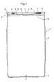
- Fig. 1 einen Längsschnitt des erfindungsgemäßen Spundfasses,
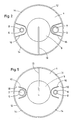
- Fig. 2 die Draufsicht des Spundfasses,
- Fig. 3 eine Einzelheit nach Ausschnitt A der Fig. 1 in vergrößerter Darstellung,
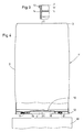
- Fig. 4 das Faß in der Kopflage zur Entleerung und
- Fig. 5 eine Draufsicht des Fasses mit einer abgeänderten Gestaltung des Deckels im Bereich der Spunde.
- 1 shows a longitudinal section of the bung barrel according to the invention,
- 2 the top view of the bung barrel,
- 3 is a detail according to section A of FIG. 1 in an enlarged view,
- Fig. 4 the barrel in the top position for emptying and
- Fig. 5 is a plan view of the barrel with a modified design of the lid in the area of the bung.
Das aus Kunststoff hergestellte Spundfaß 1 besteht aus einem Mantelteil 2, einem Boden 3 und einem Deckel 4, wobei Mantelteil 2 und Boden 3 einteiliggeb lasen sind und der als Kunststoff-Spritzteil gefertigte Deckel 4 mit dem Mantelteil 2 bei 2a über den Umfang verschweißt ist.The bung 1 made of plastic consists of a
Der Deckel 4 weist zwei diametral gegenüberliegende, einstückig angeformte Spunde 5, 6 auf, die für einen Schraubverschluß eingerichtet sind und Spundöffnungen 7, 8 bilden, die mit entsprechenden Schraubstopfen verschlossen werden können.The
Der Deckel 4 hat eine mittige, muldenartige Vertiefung 9, die bei Kopflage 1′ bzw. angenäherter Kopflage des Fasses 1 gemäß Fig. 4 zur Restentleerung eine zu den Spundöffnungen 7, 8 hin abfallende, flache Ablaufwölbung 10 für die Restflüssigkeit bildet.The
Ein am Umfang des Deckels 4 angeordneter, über die Spunde 5, 6 in Richtung der Faßlängsachse 11-11 vorstehender Außenring 12 mit einem L-Profil dient als die Spunde 5, 6 gegen Beschädigungen schützender Stützring zum Aufsetzen eines Fasses, als Tragering zum Anfassen für den Greifer eines Transportmittels und als Rollring.An on the circumference of the
Aus der mittigen Vertiefung 9 des Deckels 4 führt eine flache Ablaufrinne 13 für Regenwasser in radialer Richtung durch den Außenring 12 nach außen. Zusätzlich sind über den Umfang des Außenringes 12 verteilte Ablauföffnungen 14 vorgesehen (Fign. 2 und 3).From the
Vom Außenring 12 des Deckels 4 verlaufen mit Abstand um die Spunde 5, 6 Schutzstege 15, 16, die die gleiche Höhe 17 wie der Außenring 12 aufweisen und als Stützstege für ein gestapeltes Faß dienen.From the
Bei der in Fig. 5 dargestellten Deckelausführung weisen die Schutz- und Stützstege 15, 16 für die Spunde 5, 6 Unterbrechungen 18 im Bereich des Außenringes 12 auf, damit die Greifer eines Transportmittels über den ganzen Umfang an dem Außenring 12 ungehindert angreifen können.In the cover design shown in FIG. 5, the protective and
Bei einer weiteren Deckelausführung entfallen die Schutzstege 15, 16 für die Spunde 5, 6.In a further cover design, the
In der Kopflage 1′ bzw. angenäherten Kopflage des Fasses 1 läuft die Restflüssigkeit über die Ablaufwölbung 10 des Deckels 4 und die Spundöffnungen 7, 8 nach außen in einen Auffangbehälter 19 (Fig. 4).In the top position 1 'or approximate top position of the barrel 1, the residual liquid runs through the
Claims (8)
Priority Applications (1)
| Application Number | Priority Date | Filing Date | Title |
|---|---|---|---|
| AT90112983T ATE95132T1 (en) | 1989-07-13 | 1990-07-07 | PLUG BARREL. |
Applications Claiming Priority (2)
| Application Number | Priority Date | Filing Date | Title |
|---|---|---|---|
| DE8908528U | 1989-07-13 | ||
| DE8908528U DE8908528U1 (en) | 1989-07-13 | 1989-07-13 |
Publications (2)
| Publication Number | Publication Date |
|---|---|
| EP0407916A1 true EP0407916A1 (en) | 1991-01-16 |
| EP0407916B1 EP0407916B1 (en) | 1993-09-29 |
Family
ID=6841040
Family Applications (1)
| Application Number | Title | Priority Date | Filing Date |
|---|---|---|---|
| EP90112983A Expired - Lifetime EP0407916B1 (en) | 1989-07-13 | 1990-07-07 | Barrel with bung |
Country Status (12)
| Country | Link |
|---|---|
| US (1) | US5044510A (en) |
| EP (1) | EP0407916B1 (en) |
| JP (1) | JPH0678095B2 (en) |
| AT (1) | ATE95132T1 (en) |
| CA (1) | CA2021045C (en) |
| CS (1) | CS342890A2 (en) |
| DE (3) | DE8908528U1 (en) |
| DK (1) | DK0407916T3 (en) |
| ES (1) | ES2044329T3 (en) |
| PL (1) | PL162986B1 (en) |
| RU (1) | RU1774929C (en) |
| YU (1) | YU47978B (en) |
Families Citing this family (15)
| Publication number | Priority date | Publication date | Assignee | Title |
|---|---|---|---|---|
| DE4016600A1 (en) * | 1990-02-15 | 1991-08-22 | Mauser Werke Gmbh | TANK |
| DE4133842C2 (en) * | 1991-10-12 | 1998-10-15 | Willibrord Croonenbrock | Barrel assembly |
| DE4242370C1 (en) * | 1992-12-16 | 1994-05-11 | Schuetz Werke Gmbh Co Kg | Spigot plastics vessel - has cover held by welded ring strap which can be removed for vessel to used for another purpose or restored into new spigot vessel |
| US5273181A (en) * | 1993-01-26 | 1993-12-28 | Greif Bros. Corporation | Plastic drum with drain sump and method of making the same |
| US5449087A (en) * | 1993-09-08 | 1995-09-12 | Sonoco Products Company | Molded plastic drum |
| US6024245A (en) * | 1994-09-27 | 2000-02-15 | Greif Bros. Corp. Of Ohio, Inc. | One-piece blow-molded closed plastic drum with handling ring and method of molding same |
| DE19540542A1 (en) | 1995-10-31 | 1997-05-15 | Weber Hans Joachim | Liquid containers, such as cans, party kegs or containers |
| US7156254B2 (en) * | 1997-12-02 | 2007-01-02 | Entegis, Inc. | Blow molded drum |
| US6045000A (en) * | 1997-12-02 | 2000-04-04 | Rauworth; Barry Lee | Blow molded drum |
| DE19905898A1 (en) * | 1999-02-11 | 2000-08-24 | Kautex Maschinenbau Gmbh | Bung |
| USD422394S (en) * | 1999-04-08 | 2000-04-04 | Charles Winfield Scott | Lid for a drum |
| DE20009113U1 (en) * | 2000-05-22 | 2000-09-14 | Richter Guenter | Transport and storage device |
| US6343710B1 (en) * | 2000-10-11 | 2002-02-05 | David Rubin | Barrel-like container with cover designed for complete drainage |
| US20060108371A1 (en) * | 2004-04-18 | 2006-05-25 | Rauworth Barry L | Blow-molded drum |
| DE102004061677B4 (en) * | 2004-12-22 | 2007-05-10 | Schütz GmbH & Co. KGaA | bung barrel |
Citations (4)
| Publication number | Priority date | Publication date | Assignee | Title |
|---|---|---|---|---|
| DE2119614A1 (en) * | 1971-04-22 | 1972-11-02 | Chemische Werke Hüls AG, 4370 Mari | Plastic barrel |
| DE2219519A1 (en) * | 1972-04-21 | 1973-10-31 | Streuber Sulo Eisenwerk F | BARREL MADE OF PLASTIC |
| DD273612A1 (en) * | 1988-06-30 | 1989-11-22 | Mauser Werke Gmbh | TRANSPORTBEHAELTER |
| DD273613A1 (en) * | 1988-01-21 | 1989-11-22 | Mauser Werke Gmbh | head drum |
Family Cites Families (13)
| Publication number | Priority date | Publication date | Assignee | Title |
|---|---|---|---|---|
| US943686A (en) * | 1908-08-01 | 1909-12-21 | American Steel Package Company | Construction of receptacles. |
| US3827595A (en) * | 1970-07-27 | 1974-08-06 | Huck Finn Inc | Beer keg |
| DE2255299C2 (en) * | 1972-11-11 | 1984-03-08 | Elbatainer Kunststoff- Und Verpackungsgesellschaft Mbh, 7505 Ettlingen | Plastic barrel |
| DE2815326C2 (en) * | 1978-04-08 | 1982-09-23 | Mauser KG, 5040 Brühl | Blown bung drum |
| US4201306A (en) * | 1978-10-27 | 1980-05-06 | Greif Bros. Corporation | Variable capacity all-plastic drum |
| US4372458A (en) * | 1981-04-08 | 1983-02-08 | Carlson Franklin J | Protective skirt assembly for a container |
| US4736864A (en) * | 1986-05-02 | 1988-04-12 | S. Smith & Son Pty. Ltd. | Tank lid |
| DE8631318U1 (en) * | 1986-11-22 | 1987-01-15 | Schuetz-Werke Gmbh & Co Kg, 5418 Selters, De | |
| DE3708432A1 (en) * | 1987-03-16 | 1988-09-29 | Mauser Werke Gmbh | TANK |
| DE8709594U1 (en) * | 1987-07-11 | 1987-09-10 | Mauser-Werke Gmbh, 5040 Bruehl, De | |
| US4779754A (en) * | 1987-07-15 | 1988-10-25 | Ecolab Inc. | Draining lid |
| CH673823A5 (en) * | 1987-10-27 | 1990-04-12 | Mauser Werke Gmbh | |
| DE8713783U1 (en) * | 1987-10-14 | 1987-12-03 | Mauser-Werke Gmbh, 5040 Bruehl, De |
-
1989
- 1989-07-13 DE DE8908528U patent/DE8908528U1/de not_active Expired
- 1989-08-03 DE DE3925661A patent/DE3925661A1/en active Granted
-
1990
- 1990-07-04 PL PL28593090A patent/PL162986B1/en unknown
- 1990-07-05 YU YU129990A patent/YU47978B/en unknown
- 1990-07-06 US US07/548,846 patent/US5044510A/en not_active Expired - Fee Related
- 1990-07-07 DK DK90112983.3T patent/DK0407916T3/en active
- 1990-07-07 DE DE90112983T patent/DE59002889D1/en not_active Expired - Fee Related
- 1990-07-07 ES ES90112983T patent/ES2044329T3/en not_active Expired - Lifetime
- 1990-07-07 AT AT90112983T patent/ATE95132T1/en not_active IP Right Cessation
- 1990-07-07 EP EP90112983A patent/EP0407916B1/en not_active Expired - Lifetime
- 1990-07-11 CS CS903428A patent/CS342890A2/en unknown
- 1990-07-12 CA CA002021045A patent/CA2021045C/en not_active Expired - Fee Related
- 1990-07-12 RU SU904830455A patent/RU1774929C/en active
- 1990-07-12 JP JP18515290A patent/JPH0678095B2/en not_active Expired - Lifetime
Patent Citations (4)
| Publication number | Priority date | Publication date | Assignee | Title |
|---|---|---|---|---|
| DE2119614A1 (en) * | 1971-04-22 | 1972-11-02 | Chemische Werke Hüls AG, 4370 Mari | Plastic barrel |
| DE2219519A1 (en) * | 1972-04-21 | 1973-10-31 | Streuber Sulo Eisenwerk F | BARREL MADE OF PLASTIC |
| DD273613A1 (en) * | 1988-01-21 | 1989-11-22 | Mauser Werke Gmbh | head drum |
| DD273612A1 (en) * | 1988-06-30 | 1989-11-22 | Mauser Werke Gmbh | TRANSPORTBEHAELTER |
Also Published As
| Publication number | Publication date |
|---|---|
| RU1774929C (en) | 1992-11-07 |
| DE3925661A1 (en) | 1991-01-24 |
| ATE95132T1 (en) | 1993-10-15 |
| DE8908528U1 (en) | 1989-08-31 |
| JPH0678095B2 (en) | 1994-10-05 |
| US5044510A (en) | 1991-09-03 |
| DE59002889D1 (en) | 1993-11-04 |
| DK0407916T3 (en) | 1993-11-08 |
| ES2044329T3 (en) | 1994-01-01 |
| DE3925661C2 (en) | 1993-06-24 |
| EP0407916B1 (en) | 1993-09-29 |
| PL285930A1 (en) | 1991-02-11 |
| YU129990A (en) | 1994-06-24 |
| JPH0356232A (en) | 1991-03-11 |
| PL162986B1 (en) | 1994-01-31 |
| YU47978B (en) | 1996-08-13 |
| CA2021045A1 (en) | 1991-01-14 |
| CA2021045C (en) | 1995-08-22 |
| CS342890A2 (en) | 1991-11-12 |
Similar Documents
| Publication | Publication Date | Title |
|---|---|---|
| EP0407916A1 (en) | Barrel with bung | |
| EP0654415B1 (en) | Threaded ring on the aperture of sheet-metal containers | |
| DE3535369C2 (en) | Device for conveying a viscous fluid | |
| DE3905976C2 (en) | ||
| EP0639138B1 (en) | Plastic barrel | |
| EP0268725B1 (en) | Bung hole barrel | |
| DE2928000C2 (en) | ||
| CH654807A5 (en) | CONTAINER LID. | |
| EP0590442A1 (en) | Container for cosmetic products | |
| WO2001058801A1 (en) | Pre-table for container treatment machines | |
| CH672473A5 (en) | Closure for large plastic container - design of rim with ribbed double wall locking on to ribbed and thicker top of container with sealing ring withstands severe drop test | |
| EP0504718A1 (en) | Stackable barrel of plastic | |
| DE102004061677A1 (en) | bung barrel | |
| CH679770A5 (en) | Closure piece for thermoplastic storage or portable container for waste - has lid on which are ridges pressed onto ridges on container rim | |
| DE3423459C2 (en) | ||
| DD296895A5 (en) | MUELLBEHAELTER | |
| WO2001089942A1 (en) | Transport and storage device | |
| DE4108655A1 (en) | Stackable plastic barrel with recessed top filling and venting plugs - with gently sloping transition surrounding plug base to barrel top, ensuring complete emptying with small tilt | |
| DE102018205581A1 (en) | Cap for detergent bottle | |
| DE7608709U1 (en) | Containers especially for liquid hydrocarbons | |
| EP0661214B1 (en) | Blow-moulded barrel made of thermoplastic synthetic material | |
| DE8336794U1 (en) | Container with a removable lid | |
| EP1037816B1 (en) | Tin, especially for shoe polish and the like | |
| DE3819912A1 (en) | Bunged barrel | |
| AT394011B (en) | Transporting container |
Legal Events
| Date | Code | Title | Description |
|---|---|---|---|
| PUAI | Public reference made under article 153(3) epc to a published international application that has entered the european phase |
Free format text: ORIGINAL CODE: 0009012 |
|
| AK | Designated contracting states |
Kind code of ref document: A1 Designated state(s): AT BE CH DE DK ES FR GB GR IT LI LU NL SE |
|
| 17P | Request for examination filed |
Effective date: 19910419 |
|
| 17Q | First examination report despatched |
Effective date: 19920521 |
|
| GRAA | (expected) grant |
Free format text: ORIGINAL CODE: 0009210 |
|
| AK | Designated contracting states |
Kind code of ref document: B1 Designated state(s): AT BE CH DE DK ES FR GB GR IT LI LU NL SE |
|
| REF | Corresponds to: |
Ref document number: 95132 Country of ref document: AT Date of ref document: 19931015 Kind code of ref document: T |
|
| REF | Corresponds to: |
Ref document number: 59002889 Country of ref document: DE Date of ref document: 19931104 |
|
| REG | Reference to a national code |
Ref country code: DK Ref legal event code: T3 |
|
| GBT | Gb: translation of ep patent filed (gb section 77(6)(a)/1977) |
Effective date: 19931015 |
|
| ET | Fr: translation filed | ||
| ITF | It: translation for a ep patent filed |
Owner name: STUDIO JAUMANN |
|
| REG | Reference to a national code |
Ref country code: GR Ref legal event code: FG4A Free format text: 3009409 |
|
| REG | Reference to a national code |
Ref country code: ES Ref legal event code: FG2A Ref document number: 2044329 Country of ref document: ES Kind code of ref document: T3 |
|
| EPTA | Lu: last paid annual fee | ||
| PLBE | No opposition filed within time limit |
Free format text: ORIGINAL CODE: 0009261 |
|
| STAA | Information on the status of an ep patent application or granted ep patent |
Free format text: STATUS: NO OPPOSITION FILED WITHIN TIME LIMIT |
|
| 26N | No opposition filed | ||
| EAL | Se: european patent in force in sweden |
Ref document number: 90112983.3 |
|
| PGFP | Annual fee paid to national office [announced via postgrant information from national office to epo] |
Ref country code: FR Payment date: 19970514 Year of fee payment: 8 |
|
| PGFP | Annual fee paid to national office [announced via postgrant information from national office to epo] |
Ref country code: GB Payment date: 19970701 Year of fee payment: 8 |
|
| PGFP | Annual fee paid to national office [announced via postgrant information from national office to epo] |
Ref country code: AT Payment date: 19970702 Year of fee payment: 8 |
|
| PGFP | Annual fee paid to national office [announced via postgrant information from national office to epo] |
Ref country code: GR Payment date: 19970709 Year of fee payment: 8 |
|
| PGFP | Annual fee paid to national office [announced via postgrant information from national office to epo] |
Ref country code: LU Payment date: 19970710 Year of fee payment: 8 |
|
| PGFP | Annual fee paid to national office [announced via postgrant information from national office to epo] |
Ref country code: ES Payment date: 19970711 Year of fee payment: 8 |
|
| PGFP | Annual fee paid to national office [announced via postgrant information from national office to epo] |
Ref country code: DK Payment date: 19970714 Year of fee payment: 8 |
|
| PGFP | Annual fee paid to national office [announced via postgrant information from national office to epo] |
Ref country code: SE Payment date: 19970723 Year of fee payment: 8 |
|
| PGFP | Annual fee paid to national office [announced via postgrant information from national office to epo] |
Ref country code: NL Payment date: 19970731 Year of fee payment: 8 Ref country code: BE Payment date: 19970731 Year of fee payment: 8 |
|
| PGFP | Annual fee paid to national office [announced via postgrant information from national office to epo] |
Ref country code: DE Payment date: 19970923 Year of fee payment: 8 |
|
| PGFP | Annual fee paid to national office [announced via postgrant information from national office to epo] |
Ref country code: CH Payment date: 19971030 Year of fee payment: 8 |
|
| PG25 | Lapsed in a contracting state [announced via postgrant information from national office to epo] |
Ref country code: LU Free format text: LAPSE BECAUSE OF NON-PAYMENT OF DUE FEES Effective date: 19980707 Ref country code: GB Free format text: LAPSE BECAUSE OF NON-PAYMENT OF DUE FEES Effective date: 19980707 Ref country code: AT Free format text: LAPSE BECAUSE OF NON-PAYMENT OF DUE FEES Effective date: 19980707 |
|
| PG25 | Lapsed in a contracting state [announced via postgrant information from national office to epo] |
Ref country code: SE Free format text: LAPSE BECAUSE OF NON-PAYMENT OF DUE FEES Effective date: 19980708 Ref country code: ES Free format text: LAPSE BECAUSE OF THE APPLICANT RENOUNCES Effective date: 19980708 |
|
| PG25 | Lapsed in a contracting state [announced via postgrant information from national office to epo] |
Ref country code: LI Free format text: LAPSE BECAUSE OF NON-PAYMENT OF DUE FEES Effective date: 19980731 Ref country code: GR Free format text: LAPSE BECAUSE OF NON-PAYMENT OF DUE FEES Effective date: 19980731 Ref country code: DK Free format text: LAPSE BECAUSE OF NON-PAYMENT OF DUE FEES Effective date: 19980731 Ref country code: CH Free format text: LAPSE BECAUSE OF NON-PAYMENT OF DUE FEES Effective date: 19980731 Ref country code: BE Free format text: LAPSE BECAUSE OF NON-PAYMENT OF DUE FEES Effective date: 19980731 |
|
| BERE | Be: lapsed |
Owner name: SCHUTZ-WERKE G.M.B.H. & CO. K.G. Effective date: 19980731 |
|
| PG25 | Lapsed in a contracting state [announced via postgrant information from national office to epo] |
Ref country code: NL Free format text: LAPSE BECAUSE OF NON-PAYMENT OF DUE FEES Effective date: 19990201 |
|
| GBPC | Gb: european patent ceased through non-payment of renewal fee |
Effective date: 19980707 |
|
| REG | Reference to a national code |
Ref country code: CH Ref legal event code: PL |
|
| EUG | Se: european patent has lapsed |
Ref document number: 90112983.3 |
|
| PG25 | Lapsed in a contracting state [announced via postgrant information from national office to epo] |
Ref country code: FR Free format text: LAPSE BECAUSE OF NON-PAYMENT OF DUE FEES Effective date: 19990331 |
|
| NLV4 | Nl: lapsed or anulled due to non-payment of the annual fee |
Effective date: 19990201 |
|
| PG25 | Lapsed in a contracting state [announced via postgrant information from national office to epo] |
Ref country code: DE Free format text: LAPSE BECAUSE OF NON-PAYMENT OF DUE FEES Effective date: 19990501 |
|
| REG | Reference to a national code |
Ref country code: FR Ref legal event code: ST |
|
| REG | Reference to a national code |
Ref country code: DK Ref legal event code: EBP |
|
| REG | Reference to a national code |
Ref country code: ES Ref legal event code: FD2A Effective date: 20001102 |
|
| PG25 | Lapsed in a contracting state [announced via postgrant information from national office to epo] |
Ref country code: IT Free format text: LAPSE BECAUSE OF NON-PAYMENT OF DUE FEES Effective date: 20050707 |