EP0407856A2 - Senkkopfschraube - Google Patents
Senkkopfschraube Download PDFInfo
- Publication number
- EP0407856A2 EP0407856A2 EP90112648A EP90112648A EP0407856A2 EP 0407856 A2 EP0407856 A2 EP 0407856A2 EP 90112648 A EP90112648 A EP 90112648A EP 90112648 A EP90112648 A EP 90112648A EP 0407856 A2 EP0407856 A2 EP 0407856A2
- Authority
- EP
- European Patent Office
- Prior art keywords
- screw
- countersunk head
- countersunk
- section
- screw according
- Prior art date
- Legal status (The legal status is an assumption and is not a legal conclusion. Google has not performed a legal analysis and makes no representation as to the accuracy of the status listed.)
- Withdrawn
Links
Images
Classifications
-
- F—MECHANICAL ENGINEERING; LIGHTING; HEATING; WEAPONS; BLASTING
- F16—ENGINEERING ELEMENTS AND UNITS; GENERAL MEASURES FOR PRODUCING AND MAINTAINING EFFECTIVE FUNCTIONING OF MACHINES OR INSTALLATIONS; THERMAL INSULATION IN GENERAL
- F16B—DEVICES FOR FASTENING OR SECURING CONSTRUCTIONAL ELEMENTS OR MACHINE PARTS TOGETHER, e.g. NAILS, BOLTS, CIRCLIPS, CLAMPS, CLIPS OR WEDGES; JOINTS OR JOINTING
- F16B39/00—Locking of screws, bolts or nuts
- F16B39/22—Locking of screws, bolts or nuts in which the locking takes place during screwing down or tightening
- F16B39/28—Locking of screws, bolts or nuts in which the locking takes place during screwing down or tightening by special members on, or shape of, the nut or bolt
- F16B39/282—Locking by means of special shape of work-engaging surfaces, e.g. notched or toothed nuts
-
- F—MECHANICAL ENGINEERING; LIGHTING; HEATING; WEAPONS; BLASTING
- F16—ENGINEERING ELEMENTS AND UNITS; GENERAL MEASURES FOR PRODUCING AND MAINTAINING EFFECTIVE FUNCTIONING OF MACHINES OR INSTALLATIONS; THERMAL INSULATION IN GENERAL
- F16B—DEVICES FOR FASTENING OR SECURING CONSTRUCTIONAL ELEMENTS OR MACHINE PARTS TOGETHER, e.g. NAILS, BOLTS, CIRCLIPS, CLAMPS, CLIPS OR WEDGES; JOINTS OR JOINTING
- F16B23/00—Specially shaped nuts or heads of bolts or screws for rotations by a tool
- F16B23/0007—Specially shaped nuts or heads of bolts or screws for rotations by a tool characterised by the shape of the recess or the protrusion engaging the tool
- F16B23/003—Specially shaped nuts or heads of bolts or screws for rotations by a tool characterised by the shape of the recess or the protrusion engaging the tool star-shaped or multi-lobular, e.g. Torx-type, twelve-point star
-
- F—MECHANICAL ENGINEERING; LIGHTING; HEATING; WEAPONS; BLASTING
- F16—ENGINEERING ELEMENTS AND UNITS; GENERAL MEASURES FOR PRODUCING AND MAINTAINING EFFECTIVE FUNCTIONING OF MACHINES OR INSTALLATIONS; THERMAL INSULATION IN GENERAL
- F16B—DEVICES FOR FASTENING OR SECURING CONSTRUCTIONAL ELEMENTS OR MACHINE PARTS TOGETHER, e.g. NAILS, BOLTS, CIRCLIPS, CLAMPS, CLIPS OR WEDGES; JOINTS OR JOINTING
- F16B35/00—Screw-bolts; Stay-bolts; Screw-threaded studs; Screws; Set screws
- F16B35/04—Screw-bolts; Stay-bolts; Screw-threaded studs; Screws; Set screws with specially-shaped head or shaft in order to fix the bolt on or in an object
- F16B35/06—Specially-shaped heads
-
- F—MECHANICAL ENGINEERING; LIGHTING; HEATING; WEAPONS; BLASTING
- F16—ENGINEERING ELEMENTS AND UNITS; GENERAL MEASURES FOR PRODUCING AND MAINTAINING EFFECTIVE FUNCTIONING OF MACHINES OR INSTALLATIONS; THERMAL INSULATION IN GENERAL
- F16B—DEVICES FOR FASTENING OR SECURING CONSTRUCTIONAL ELEMENTS OR MACHINE PARTS TOGETHER, e.g. NAILS, BOLTS, CIRCLIPS, CLAMPS, CLIPS OR WEDGES; JOINTS OR JOINTING
- F16B25/00—Screws that cut thread in the body into which they are screwed, e.g. wood screws
Definitions
- the invention relates to a screw with a countersunk head and a screw shaft, which has a thread extending to the countersunk head.
- Screws of this type are used for example in window construction.
- the countersunk heads have approximately the shape of a truncated cone, the conical surfaces of which usually have a certain opening angle.
- the side flank of the countersunk head encloses an angle of 45 ° with the longitudinal axis.
- the countersunk openings of fitting parts or the like are also adapted to this course of the cone.
- a screw is already known (US Pat. No. 3,255,797) in which a countersunk head merges into the screw shaft via a flat underside.
- the countersunk head itself is, however, more pointed than conventional countersunk heads, so that its axial length is greater than the conventional countersunk heads.
- the screw has no drive in its head because it is tightened by tightening a nut and should not turn.
- the screw is intended for use with non-countersunk holes.
- a screw (GB-A-11 12 810) in which the approximately lenticular head has two sharp deformable peripheral edges in the area of the conical outside.
- the truncated cone area is rounded between the edges. The edges should be deformed when tightening the screw to create a seal.
- the thread of the screw extends over about 1/3 of the shaft.
- the invention has for its object to provide a countersunk screw which is particularly suitable for window construction and which is very suitable for fastening two relatively thin objects to one another.
- the invention proposes to construct the countersunk head with two countersunk screws, one area of which starts from the end of the countersunk head, that is to say from its flat end face, and has a shape corresponding to the shape of conventional countersunk heads, but is shorter. This is followed by a flatter area that extends to the threaded shaft.
- the flatter area can, for example, also be a truncated cone with a correspondingly truncated cone angle. However, it is also conceivable for this area to be curved or curved overall.
- the axial dimension of the countersunk head is shorter than that of a normal countersunk head.
- normal countersunk heads their axial extension is determined by the outside diameter of the threaded shaft, the opening angle of the countersunk head and its outside diameter. Since these sizes are all fixed, the axial dimension is also determined.
- the measure according to the invention makes it possible, however, to design the countersunk head as a whole to be shorter, so that, in the case of the conventional fittings or the usual profile dimensions, the thread again reaches the head.
- the drive of the screw is formed by a recess which is delimited in a section lying in the longitudinal axis of the screw by approximately parallel to the longitudinal axis of the screw side surfaces.
- drive recesses are a hexagon shape or a shape which is formed by alternately concave and convexly curved circular arcs which merge smoothly into one another.
- the Phillips drives often used in countersunk screws have a correspondingly divergent side surface, which would lead to the fact that the recess in a screw according to the invention could only be made relatively flat in the screw head, so that the material of the screw head in the area of the underside was not gets too thin.
- the recessed cross recesses also have a customary shape, their use is one screw proposed by the invention is not particularly cheap.
- the drive recesses proposed by the invention have the advantage that they can apply high torques and the screw head is nevertheless not hollowed out so deeply that the special proposed shape would no longer be possible.
- the countersunk screw contains a screw shaft 11 which merges into a countersunk head 12 in the region of the one end of the screw provided with a drive.
- the countersunk head 12 is delimited by a flat end surface 13.
- the end face 13 is followed by a very short cylindrical section 14.
- the screw shaft 11 is provided with circumferential thread 15.
- the thread is formed right up to the underside of the countersunk head 12. It is made by rolling.
- the countersunk head 12 contains a section 16 immediately following the flat cylindrical section 14, in which the outside or underside of the countersunk head 12 lies in a truncated cone surface.
- the edge of this section 16 lying in the cross section of the figure encloses an angle of approximately 45 ° or otherwise with the longitudinal axis of the screw expressed, the end edges of section 16 visible in section run at a right angle to one another.
- a second section 18 adjoins the first section 16 of the countersunk head, in which the underside or outer surface of the countersunk head 12 lies on a significantly flatter truncated cone.
- the edges of this second section 18 visible in section each run at an angle of approximately 76 ° with respect to the longitudinal axis of the screw.
- This second section 18 merges directly into the threaded shaft 11 via a further edge 19.
- the edges 17 and 19 are rounded.
- the thread 15 rolled on the shaft 11 can reach much closer to the underside of the countersunk head 12 or also closer to the end face 13 of the screw.
- the recesses 21 has one for the transmission of torques the screw head has a non-circular outer shape.
- the recess 21 can be a hexagon recess.
- the recess 21 has side faces 22 which run approximately parallel to one another and to the longitudinal axis of the screw.
- the side surfaces 22 can diverge slightly, for example in a range of 2 °.
- the bottom 23 of the recess 21 is made relatively flat, for example it has a tip angle 24 of approximately 135 ° -140 °.
- An outer shape of the recess 21 is particularly preferred, in which six concave and six convex arcs alternate in succession, the transitions of which are smooth. With such a recess high torques can be transmitted so that the relatively small depth of the recess 21 is sufficient for the screw.
- region 18 is formed by a truncated cone surface, it could also be somewhat rounded overall, that is to say correspond approximately to a spherical surface.
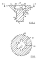
- Fig. 2 now shows a cross section through the screw of Fig. 1 somewhat along the line II-II.
- the mentioned shape of the recess 21 can be seen from this cross section.
- the recess 21 is formed by side surfaces 22, which are composed of six concave and six convex circular arc-shaped curvatures.
- six arches 26 facing inwards and six arches 27 facing outwards are formed.
- the outwardly facing arches 27 have approximately half the radius as the inwardly facing arches 26.
- Such a shape of the recess 21 is particularly favorable for the transmission of high torques, so that it is preferred.
- the screw has 16 ribs 25 on the underside of its screw head in the region of the first conical section, which are close to one another and are approximately semicircular in cross section.
- the longitudinal axes of the ribs 25 intersect the longitudinal axis of the screw shaft 11.
- the ribs 25 on the underside of the screw head form a securing means for the screw that is tightened, which prevents the screw from being unintentionally loosened, for example in the event of vibrations.
- the ribs 25 can be molded in the same operation in the manufacture of the screw, so that no additional effort is required. It has proven to be particularly useful if there are about 12 to 20 ribs 25.
- the screw has a flat upper side 13.
- this upper side or end face 13 may be slightly curved, as is the case with conventional oval head screws. Raised-head screws should also fall under the term countersunk screw used by the invention.
- the underside of the countersunk head 12 lies in the second section 18 on a flat truncated cone with an apex angle of approximately 150 °. This angle is somewhat larger than the apex angle 24 of the base 23 of the recess 21. In the extreme case, the flatter region 18 can also be designed so flat that it approaches a plane.
Landscapes
- Engineering & Computer Science (AREA)
- General Engineering & Computer Science (AREA)
- Mechanical Engineering (AREA)
- Connection Of Plates (AREA)
- Extrusion Moulding Of Plastics Or The Like (AREA)
Abstract
Eine insbesondere als Fensterbauschraube gedachte Senkkopfschraube weist auf ihrem Gewindeschaft (11) ein bis zum Senkkopf (12) reichendes Gewinde (15) auf. Der Senkkopf (12) ist aus einem ersten kegelförmigen Abschnitt (16) aufgebaut, an den sich ein zweiter deutlich flacherer Abschnitt (18) anschließt. Der erste kegelstumpfförmige Abschnitt (16) entspricht in seinem Öffnungswinkel dem Öffnungswinkel üblicher Senkkopfschrauben, hat jedoch in Längsrichtung der Schraube gesehen eine kürzere Länge. Dadurch verringert sich die Gesamtlänge des Senkkopfs (12) und das Gewinde (15) läßt sich bis näher an das Senkkopfende der Schraube hin vollständig aufwalzen.
Description
- Die Erfindung betrifft eine Schraube mit einem Senkkopf und einem Schraubenschaft, der ein bis zum Senkkopf reichendes Gewinde aufweist.
- Schrauben dieser Art werden beispielsweise im Fensterbau verwendet. Die Senkköpfe haben etwa die Form eines Kegelstumpfes, dessen Kegelflächen üblicherweise einen bestimmten Öffnungswinkel aufweisen. Bei allen derzeit bekannten Schrauben dieser Art schließt die Seitenflanke des Senkkopfs mit der Längsachse einen Winkel von 45° ein. Diesem Kegelverlauf sind auch die angesenkten Öffnungen von Beschlagteilen oder dergleichen angepaßt.
- Im Fensterbau tritt häufig das Problem auf, daß zwei Profile aufeinander festgeschraubt werden sollen, wobei die Profile gegebenfalls relativ dünn sind. Aus diesem Grunde muß das Gewinde des Schraubenschaftes bis an die Unterseite des Senkkopfes heranreichen. Es ist jedoch relativ schwierig, an der Unterseite eines derartigen kegelstumpfförmigen Senkkopfes ein Gewinde bis an diese Unterseite heranreichend voll auszuwalzen.
- Es ist bereits eine Schraube bekannt (US-A-32 55 797), bei der ein Senkkopf über eine flache Unterseite in den Schraubenschaft übergeht. Der Senkkopf selbst ist aber spitzer ausgebildet als übliche Senkköpfe, so daß seine axiale Länge größer ist als die üblicher Senkköpfe. Die Schraube enthält in ihrem Kopf keinen Antrieb, da sie durch Festziehen einer Mutter angezogen wird und sich nicht drehen soll. Die Schraube ist zur Verwendung mit nicht angesenkten Löchern bestimmt.
- Ebenfalls bekannt ist eine Schraube (GB-A-11 12 810), bei der der etwa linsenförmig ausgebildete Kopf dem Bereich der kegelförmigen Außenseite zwei scharfe deformierbare umlaufende Kanten aufweist. Zwischen den Kanten verläuft der Kegelstumpfbereich abgerundet. Die Kanten sollen beim Festziehen der Schraube zur Herstellung einer Dichtung verformt werden. Das Gewinde der Schraube erstreckt sich über etwa 1/3 des Schaftes.
- Der Erfindung liegt die Aufgabe zugrunde, eine insbesondere für den Fensterbau geeignete Senkkopfschraube zu schaffen, die zur Befestigung zweier relativ dünner Gegenstände aneinander sehr gut geeignet ist.
- Zur Lösung dieser Aufgabe schlägt die Erfindung vor, bei einer Senkkopfschraube den Senkkopf aus zwei Bereichen aufzubauen, von denen der eine Bereich vom Ende des Senkkopfs, also von dessen ebener Endfläche, ausgeht und einen der Form üblicher Senkköpfe entsprechende Form aufweist, jedoch kürzer ist. Daran schließt sich ein bis zum Gewindeschaft reichender flacherer Bereich an.
- Auf diese relativ einfache Weise wird an der Unterseite des Senkkopfs ausreichend Platz geschaffen, so daß das Gewinde voll ausgewalzt bis an den Senkkopf heranreichen kann.
- Der flachere Bereich kann beispielsweise ebenfalls ein Kegelstumpf mit einem entsprechend stumpferen Kegelwinkel sein. Es ist jedoch auch denkbar, diesen Bereich insgesamt gebogen oder gekrümmt verlaufen zu lassen.
- In Weiterbildung der Erfindung kann vorgesehen sein, daß die axiale Abmessung des Senkkopfs kürzer als diejenige eines normalen Senkkopfs ist. Bei den normalen Senkköpfen wird deren axiale Erstreckung durch den Außendurchmesser des Gewindeschafts, den Öffnungswinkel des Senkkopfs und seinen Außendurchmesser bestimmt. Da diese Größen alle festgelegt sind, ist damit auch die axiale Abmessung bestimmt. Die Maßnahme nach der Erfindung macht es jedoch möglich, den Senkkopf insgesamt kürzer auszubilden, so daß bei den herkömmlichen Beschlägen oder üblichen Profilabmessungen das Gewinde nochmals weiter zum Kopf heranreicht.
- Die Erfindung schlägt in Weiterbildung vor, daß der Antrieb der Schraube von einer Ausnehmung gebildet wird, die in einem in der Längsachse der Schraube liegenden Schnitt von etwa parallel zur Schraubenlängsachse verlaufenden Seitenflächen begrenzt wird. Beispiele für derartige Antriebsausnehmungen ist eine Sechskantform oder eine Form, die durch abwechselnd konkav- und konvex gekrümmte glatt ineinander übergehende Kreisbögen gebildet wird.
- Die bei Senkkopfschrauben häufig verwendeten Kreuzschlitzantriebe weisen in einem entsprechenden Schnitt stark divergierende Seitenflächen auf, die dazu führen würden, daß bei einer Schraube nach der Erfindung die Ausnehmung nur relativ flach in den Schraubenkopf eingebracht werden könnte, damit das Material des Schraubenkopfes im Bereich der Unterseite nicht zu dünn wird. Da aber auch die Kreuzschlitzausparungen eine übliche Form aufweisen, ist ihre Verwendung bei einer von der Erfindung vorgeschlagen Schraube nicht besonders günstig. Die von der Erfindung vorgeschlagenen Antriebsausnehmungen haben den Vorteil, daß sie große Drehmomente aufbringen können und der Schraubenkopf dennoch nicht so tief ausgehöhlt ist, daß die spezielle vorgeschlagene Form nicht mehr möglich wäre.
- Weite Merkmale, Einzelheiten und Vorzüge der Erfindung ergeben sich aus der folgenden Beschreibung einer bevorzugten Ausführungsform sowie anhand der Zeichnung. Hierbei zeigen:
- Fig. 1 einen Längsschnitt durch den oberen Endabschnitt einer Senkkopfschraube,
- Fig 2 einen Querschnitt etwa längs Linie II-II in Fig 1.
- Die Senkkopfschraube enthält einen Schraubenschaft 11, der im Bereich des einen mit einem Antrieb versehenen Endes der Schraube in einen Senkkopf 12 übergeht. Der Senkkopf 12 wird von einer ebenen Abschlußfläche 13 begrenzt. An die Abschlußfläche 13 schließt sich sehr kurzer zylindrischer Abschnitt 14 an.
- Der Schraubenschaft 11 ist mit umlaufenden Gewinde 15 versehen. Das Gewinde ist bis unmittelbar an die Unterseite des Senkkopfs 12 ausgebildet. Es ist durch Walzen hergestellt. Der Senkkopf 12 enthält unmittelbar im Anschluß an den flachen zylindrischen Abschnitt 14 einen Abschnitt 16, in dem die Außenseite bzw. Unterseite des Senkkopfs 12 in einer Kegelstumpffläche liegt. Die im Querschnitt der Figur liegende Kante dieses Abschnittes 16 schließt mit der Längsachse der Schraube einen Winkel von rund 45° ein oder anders ausgedrückt, verlaufen die im Schnitt sichtbaren Abschlußkanten des Abschnittes 16 unter einem rechten Winkel zueinander. Durch eine Kante 17 getrennt schließt sich an den ersten Abschnitt 16 des Senkkopfs ein zweiter Abschnitt 18 an, in dem die Unterseite bzw. Außenfläche des Senkkopfs 12 auf einem deutlich flacheren Kegelstumpf liegt. Beispielsweise verlaufen die im Schnitt sichtbaren Kanten dieses zweiten Abschnittes 18 jeweils unter einem Winkel von etwa 76° gegenüber der Längsachse der Schraube.
- Dieser zweite Abschnitt 18 geht unmittelbar über eine weitere Kante 19 in den Gewindeschaft 11 über. Bei einer tatsächlich hergestellten Ausführungsform verlaufen die Kanten 17 und 19 verrundet.
- Aufgrund der flacheren Anordnung des zweiten Senkkopfabschnitts 18 ist die gesamte in axialer Richtung gemessene
- Abmessung des Senkkopfs, also der in Axialrichtung gemessene Abstand der Abschlußfläche 13 von der Kante 19, deutlich kürzer als dies bei normalen Senkköpfen der Fall wäre. Dies ist durch die gestrichelte Linie 20 angedeutet, die die geradlinige Verlängerung des ersten Senkkopfabschnittes 16 darstellt.
- Aufgrund der kürzeren Ausbildung des Senkkopfs 12 bei unveränderter Geometrie im ersten Abschnitt 16 kann das auf dem Schaft 11 aufgewalzte Gewinde 15 wesentlich näher an die Unterseite des Senkkopfs 12 bzw. auch näher an die Abschlußfläche 13 der Schraube heranreichen.
- Zum Antrieb der Senkkopfschraube weist diese eine in ihrer Abschlußfläche 13 mündende Ausnehmung 21 auf. Die Ausnehmungen 21 weist zur Übertragung von Drehmomenten eine in Auf sicht auf den Schraubenkopf nicht kreisrunde Außenform auf. Beispielsweise kann es sich um eine Sechskantausnehmung handeln. In dem in der Figur dargestellten Längsschnitt durch die Schraube weist die Ausnehmung 21 Seitenflächen 22 auf, die etwa parallel zueinander und zu der Längsachse der Schraube verlaufen. Die Seitenflächen 22 können leicht divergieren, etwa in einem Bereich von 2°. Der Boden 23 der Ausnehmung 21 ist relativ flach ausgebildet, beispielsweise weist er einen Spitzenwinkel 24 von etwa 135° - 140° auf.
- Besonders bevorzugt ist eine Außenform der Ausnehmung 21, bei der sechs konkave und sechs konvexe Kreisbögen abwechselnd aufeinanderfolgen, deren Übergänge glatt sind. Mit einer derartigen Ausnehmung können hohe Drehmomente übertragen werden, so daß die relativ geringe Tiefe der Ausnehmung 21 völlig für die Schraube ausreicht.
- Während bei der dargestellten Ausführungsform der Bereich 18 von einer Kegelstumpffläche gebildet wird, könnte er auch insgesamt etwas abgerundet verlaufen, also etwa einer Kugelfläche entsprechen.
- Fig. 2 zeigt nun einen Querschnitt durch die Schraube der Fig. 1 etwas längs der Linie II-II. Aus diesem Querschnitt ist die erwähnte Form der Ausnehmung 21 entnehmbar. Die Ausnehmung 21 wird von Seitenflächen 22 gebildet, die sich aus sechs konkaven und sechs konvexen kreisbogenförmigen Krümmungen zusammensetzen. Dadurch werden sechs nach innen gewandte Bögen 26 und sechs nach außen gewandte Bögen 27 gebildet. Die nach außen gewandten Bögen 27 haben etwa den halben Radius wie die nach innen gewandten Bögen 26. Eine derartige Form der Ausnehmung 21 ist zur Übertragung hoher Drehmomente besonders günstig, so daß sie bevorzugt wird. Selbstverständlich ist jedoch auch eine sechskantige Ausneh mung 21 möglich.
- Wie sich ebenfalls aus Fig. 2 ergibt, besitzt die Schraube an der Unterseite ihres Schraubenkopfes im Bereich des ersten kegelförmigen Abschnittes 16 Rippen 25, die dicht an dicht liegen und im Querschnitt etwa halbkreisförmig sind. Die Längsachsen der Rippen 25 schneiden die Längsachse des Schraubenschaftes 11. Die Rippen 25 an der Unterseite des Schraubenkopfes bilden eine Sicherung für die festgedrehte Schraube, die ein unbeabsichtigtes Lösen der Schraube, beispielsweise bei Vibrationen, verhindert. Die Rippen 25 können bei der Herstellung der Schraube im gleichen Arbeitsgang mitangeformt werden, so daß kein zusätzlicher Aufwand erforderlich ist. Als besonders sinnvoll hat es sich gezeigt, wenn etwa 12 bis 20 Rippen 25 vorhanden sind.
- Bei der Ausführungsform, die in den Figuren dargestellt ist, weist die Schraube eine ebene Oberseite 13 auf. Selbstverständlich ist es auch möglich, daß diese Oberseite bzw. Abschlußfläche 13 leicht gekrümmt verläuft wie dies bei den herkömmlichen Linsenkopfschrauben der Fall. Linsenkopfschrauben sollen also auch unter den von der Erfindung verwendeten Begriff der Senkkopfschraube fallen.
- Bei der in den Figuren dargestellten Ausführungsform liegt die Unterseite des Senkkopfs 12 in dem zweiten Abschnitt 18 auf einem flachen Kegelstumpf mit einem Spitzenwinkel von etwa 150°. Dieser Winkel ist etwas größer als der Spitzenwinkel 24 des Bodens 23 der Ausnehmung 21. Der flachere Bereich 18 kann im Extremfall auch derart flach ausgebildet werden, daß er sich einer Ebene annähert.
Claims (10)
1. Schraube mit einem Senkkopf (12) und einem Schraubenschaft (11), der ein bis zum Senkkopf (12) reichendes Gewinde (15) aufweist, dadurch gekennzeichnet, daß der Senkkopf (12) einen von seinem Ende (13) ausgehenden ersten kegelförmigen Bereich (16) mit einer der Form üblicher Senkköpfe entsprechenden Form aber kürzerer axialer Länge und einen sich daran anschließenden bis zum Schaft (11) reichenden flacheren Bereich (18) aufweist.
2. Schraube nach Anspruch 1, dadurch gekennzeichnet, daß die axiale Abmessung des Senkkopfs (12) kürzer ist als diejenige eines üblichen Senkkopfs.
3. Schraube nach Anspruch 1 oder 2, dadurch gekennzeichnet, daß der Antrieb der Schraube von einer Ausnehmung (21) gebildet wird, die vorzugsweise im Schraubenlängsschnitt etwa parallel zu der Schraubenlängsachse verlaufende Seitenfläche (22) aufweist
4. Schraube nach einem der vorhergehenden Ansprüche, dadurch gekennzeichnet, daß der Übergang zwischen den beiden Bereichen (16, 18) des Senkkopfs (12) verrundet verläuft.
5. Schraube nach einem der vorhergehenden Ansprüche, dadurch gekennzeichnet, daß der zweite Abschnitt (18) kegelstumpfförmig ausgebildet ist.
6. Schraube nach einem der Ansprüche 3 - 5, dadurch gekennzeichnet, daß die Ausnehmung (21) Sechskantform aufweist.
7. Schraube nach einem der Ansprüche 1 - 5, dadurch gekennzeichnet, daß die Ausnehmung (21) die Form abwechselnd konkav und konvex gekrümmter glatt ineinander übergehender Kreisbögen aufweist.
8. Schraube nach einem der vorhergehenden Ansprüche, dadurch gekennzeichnet, daß sie an der Unterseite des Senkkopfs (12) im ersten kegelförmigen Bereich (16) eine Verrippung aufweist, die von in Längsrichtung der Schraube verlaufenden Rippen (25) gebildet ist, die vorzugsweise dicht benachbart zueinander angeordnet sind.
9. Schraube nach Anspruch 8, dadurch gekennzeichnet, daß der Querschnitt der Rippen (25) etwa Halbkreisform aufweist.
10. Verwendung einer Schraube nach einem der vorhergehenden Ansprüche als Schraube zum Verbinden zweier Bleche, von denen mindestens das eine dünn ist, ohne Mutter.
Applications Claiming Priority (2)
| Application Number | Priority Date | Filing Date | Title |
|---|---|---|---|
| DE19893923091 DE3923091A1 (de) | 1989-07-13 | 1989-07-13 | Senkkopfschraube |
| DE3923091 | 1989-07-13 |
Publications (2)
| Publication Number | Publication Date |
|---|---|
| EP0407856A2 true EP0407856A2 (de) | 1991-01-16 |
| EP0407856A3 EP0407856A3 (en) | 1991-08-07 |
Family
ID=6384908
Family Applications (1)
| Application Number | Title | Priority Date | Filing Date |
|---|---|---|---|
| EP19900112648 Withdrawn EP0407856A3 (en) | 1989-07-13 | 1990-07-03 | Countersunk head screw |
Country Status (2)
| Country | Link |
|---|---|
| EP (1) | EP0407856A3 (de) |
| DE (1) | DE3923091A1 (de) |
Cited By (3)
| Publication number | Priority date | Publication date | Assignee | Title |
|---|---|---|---|---|
| EP0558831A1 (de) * | 1992-03-05 | 1993-09-08 | Gebu Draadwarenfabriek Ing H.G. Geist B.V. | Schraube oder Schraubenbolzen |
| US5516173A (en) * | 1993-03-15 | 1996-05-14 | Btm Corporation | Gripper |
| US20210246928A1 (en) * | 2020-02-11 | 2021-08-12 | Carl Chasse | Fastener having improved wobble control, fastening system including the same, and method of forming the same |
Families Citing this family (1)
| Publication number | Priority date | Publication date | Assignee | Title |
|---|---|---|---|---|
| DE10061559A1 (de) † | 2000-12-07 | 2002-06-13 | C & E Fein Gmbh & Co Kg | Aufnahme zur Befestigung eines Werkzeuges an einer Antriebswelle und Adapter hierzu |
Family Cites Families (12)
| Publication number | Priority date | Publication date | Assignee | Title |
|---|---|---|---|---|
| US2982166A (en) * | 1958-07-24 | 1961-05-02 | Robert W Hobbs | Fastener head the underlying surface of which has means to smooth the workpiece surface |
| US3178984A (en) * | 1963-02-01 | 1965-04-20 | Charles F Barothy | Screw dowel |
| US3255797A (en) * | 1964-06-15 | 1966-06-14 | Warren R Attwood | Structural assemblies |
| NL128843C (de) * | 1965-07-28 | |||
| NL6710350A (de) * | 1966-09-19 | 1968-03-20 | ||
| DE7106600U (de) * | 1971-02-22 | 1975-07-10 | Hettich P & Co | Senkschraube zum Verbinden eines starren Beschlagteils mit einem Kunststoffteil |
| DE2108339C3 (de) * | 1971-02-22 | 1978-05-24 | Paul Hettich & Co, 4983 Kirchlengern | Verwendung einer Senkkopfschraube zum Verbinden eines Bauteils aus starrem Material mit einem Bauteil aus Kunststoff |
| DE2260443A1 (de) * | 1972-12-11 | 1974-06-12 | Schnegelsiepen & Wesser Fasson | Schraube oder huelsenschraube |
| US3849964A (en) * | 1973-08-15 | 1974-11-26 | F Briles | Corrosion blocking fastener |
| GB1524047A (en) * | 1975-09-16 | 1978-09-06 | Textron Inc | Self-clinching fasteners |
| US4111580A (en) * | 1976-12-30 | 1978-09-05 | The Boeing Company | Continuously curved fastener head and countersink have interference fit |
| DE3531376A1 (de) * | 1985-09-03 | 1987-05-21 | Wieland Werke Ag | Eck- oder stossverbindung zweier hohlprofile fuer fenster-, tuerrahmen od. dgl. |
-
1989
- 1989-07-13 DE DE19893923091 patent/DE3923091A1/de not_active Withdrawn
-
1990
- 1990-07-03 EP EP19900112648 patent/EP0407856A3/de not_active Withdrawn
Cited By (4)
| Publication number | Priority date | Publication date | Assignee | Title |
|---|---|---|---|---|
| EP0558831A1 (de) * | 1992-03-05 | 1993-09-08 | Gebu Draadwarenfabriek Ing H.G. Geist B.V. | Schraube oder Schraubenbolzen |
| US5516173A (en) * | 1993-03-15 | 1996-05-14 | Btm Corporation | Gripper |
| US5647625A (en) * | 1993-03-15 | 1997-07-15 | Btm Corporation | Gripper |
| US20210246928A1 (en) * | 2020-02-11 | 2021-08-12 | Carl Chasse | Fastener having improved wobble control, fastening system including the same, and method of forming the same |
Also Published As
| Publication number | Publication date |
|---|---|
| EP0407856A3 (en) | 1991-08-07 |
| DE3923091A1 (de) | 1991-01-24 |
Similar Documents
| Publication | Publication Date | Title |
|---|---|---|
| EP0869287B1 (de) | Selbtlochendes und gewindeformendes Verbindungselement | |
| EP2310697B1 (de) | Schraube | |
| EP2521864B1 (de) | Gewindeformende schraube und ihre verwendung | |
| EP2021639B1 (de) | Selbstbohrende schraube | |
| EP0464071B1 (de) | Loch- und gewindeformende schraube | |
| DE69304631T2 (de) | Selbstbohrende schraube | |
| WO2005080802A1 (de) | Gewindeformende schraube | |
| EP1031741A1 (de) | Senkkopfschraube | |
| DE1400229B1 (de) | Selbstgewindeherstellende Schraube | |
| EP3004666A1 (de) | Schraube | |
| EP0939235B1 (de) | Schraube | |
| EP2229538A1 (de) | Befestigungselement | |
| EP1031742A1 (de) | Senkkopfschraube | |
| EP2150709B1 (de) | Spanplattenschraube | |
| EP1165974A1 (de) | Senkkopfschraube | |
| EP1718876A1 (de) | Gewindeformende schraube | |
| DE3117624A1 (de) | Selbstformende universalschraube | |
| DE4444467A1 (de) | Gewindeschneidschraube | |
| EP3374649B1 (de) | Gewindeformende schraube | |
| DE4108771A1 (de) | Spanplattenschraube | |
| EP2646697A2 (de) | Selbstsichernde mutter | |
| EP0447902A1 (de) | Schraube zum Befestigen von Gipskartonplatten | |
| WO1999011436A1 (de) | Kraftübertragungsprofil, insbesondere an einem mehrkant-schraubwerkzeug | |
| EP0257664A1 (de) | Innenantrieb, Abdeckkappe und Schraubendreher für eine Universalschraube | |
| EP0407856A2 (de) | Senkkopfschraube |
Legal Events
| Date | Code | Title | Description |
|---|---|---|---|
| PUAI | Public reference made under article 153(3) epc to a published international application that has entered the european phase |
Free format text: ORIGINAL CODE: 0009012 |
|
| AK | Designated contracting states |
Kind code of ref document: A2 Designated state(s): AT BE CH DE DK ES FR GB GR IT LI LU NL SE |
|
| PUAL | Search report despatched |
Free format text: ORIGINAL CODE: 0009013 |
|
| AK | Designated contracting states |
Kind code of ref document: A3 Designated state(s): AT BE CH DE DK ES FR GB GR IT LI LU NL SE |
|
| STAA | Information on the status of an ep patent application or granted ep patent |
Free format text: STATUS: THE APPLICATION IS DEEMED TO BE WITHDRAWN |
|
| 18D | Application deemed to be withdrawn |
Effective date: 19920208 |