EP0407856A2 - Vis à tête conique - Google Patents
Vis à tête conique Download PDFInfo
- Publication number
- EP0407856A2 EP0407856A2 EP90112648A EP90112648A EP0407856A2 EP 0407856 A2 EP0407856 A2 EP 0407856A2 EP 90112648 A EP90112648 A EP 90112648A EP 90112648 A EP90112648 A EP 90112648A EP 0407856 A2 EP0407856 A2 EP 0407856A2
- Authority
- EP
- European Patent Office
- Prior art keywords
- screw
- countersunk head
- countersunk
- section
- screw according
- Prior art date
- Legal status (The legal status is an assumption and is not a legal conclusion. Google has not performed a legal analysis and makes no representation as to the accuracy of the status listed.)
- Withdrawn
Links
- 230000004323 axial length Effects 0.000 claims description 2
- 230000007704 transition Effects 0.000 claims description 2
- 238000009434 installation Methods 0.000 abstract 1
- 238000010276 construction Methods 0.000 description 3
- 230000005540 biological transmission Effects 0.000 description 2
- 230000018109 developmental process Effects 0.000 description 2
- 238000013459 approach Methods 0.000 description 1
- 230000002349 favourable effect Effects 0.000 description 1
- 238000004519 manufacturing process Methods 0.000 description 1
- 230000002093 peripheral effect Effects 0.000 description 1
- 238000005096 rolling process Methods 0.000 description 1
Images
Classifications
-
- F—MECHANICAL ENGINEERING; LIGHTING; HEATING; WEAPONS; BLASTING
- F16—ENGINEERING ELEMENTS AND UNITS; GENERAL MEASURES FOR PRODUCING AND MAINTAINING EFFECTIVE FUNCTIONING OF MACHINES OR INSTALLATIONS; THERMAL INSULATION IN GENERAL
- F16B—DEVICES FOR FASTENING OR SECURING CONSTRUCTIONAL ELEMENTS OR MACHINE PARTS TOGETHER, e.g. NAILS, BOLTS, CIRCLIPS, CLAMPS, CLIPS OR WEDGES; JOINTS OR JOINTING
- F16B39/00—Locking of screws, bolts or nuts
- F16B39/22—Locking of screws, bolts or nuts in which the locking takes place during screwing down or tightening
- F16B39/28—Locking of screws, bolts or nuts in which the locking takes place during screwing down or tightening by special members on, or shape of, the nut or bolt
- F16B39/282—Locking by means of special shape of work-engaging surfaces, e.g. notched or toothed nuts
-
- F—MECHANICAL ENGINEERING; LIGHTING; HEATING; WEAPONS; BLASTING
- F16—ENGINEERING ELEMENTS AND UNITS; GENERAL MEASURES FOR PRODUCING AND MAINTAINING EFFECTIVE FUNCTIONING OF MACHINES OR INSTALLATIONS; THERMAL INSULATION IN GENERAL
- F16B—DEVICES FOR FASTENING OR SECURING CONSTRUCTIONAL ELEMENTS OR MACHINE PARTS TOGETHER, e.g. NAILS, BOLTS, CIRCLIPS, CLAMPS, CLIPS OR WEDGES; JOINTS OR JOINTING
- F16B23/00—Specially shaped nuts or heads of bolts or screws for rotations by a tool
- F16B23/0007—Specially shaped nuts or heads of bolts or screws for rotations by a tool characterised by the shape of the recess or the protrusion engaging the tool
- F16B23/003—Specially shaped nuts or heads of bolts or screws for rotations by a tool characterised by the shape of the recess or the protrusion engaging the tool star-shaped or multi-lobular, e.g. Torx-type, twelve-point star
-
- F—MECHANICAL ENGINEERING; LIGHTING; HEATING; WEAPONS; BLASTING
- F16—ENGINEERING ELEMENTS AND UNITS; GENERAL MEASURES FOR PRODUCING AND MAINTAINING EFFECTIVE FUNCTIONING OF MACHINES OR INSTALLATIONS; THERMAL INSULATION IN GENERAL
- F16B—DEVICES FOR FASTENING OR SECURING CONSTRUCTIONAL ELEMENTS OR MACHINE PARTS TOGETHER, e.g. NAILS, BOLTS, CIRCLIPS, CLAMPS, CLIPS OR WEDGES; JOINTS OR JOINTING
- F16B35/00—Screw-bolts; Stay-bolts; Screw-threaded studs; Screws; Set screws
- F16B35/04—Screw-bolts; Stay-bolts; Screw-threaded studs; Screws; Set screws with specially-shaped head or shaft in order to fix the bolt on or in an object
- F16B35/06—Specially-shaped heads
-
- F—MECHANICAL ENGINEERING; LIGHTING; HEATING; WEAPONS; BLASTING
- F16—ENGINEERING ELEMENTS AND UNITS; GENERAL MEASURES FOR PRODUCING AND MAINTAINING EFFECTIVE FUNCTIONING OF MACHINES OR INSTALLATIONS; THERMAL INSULATION IN GENERAL
- F16B—DEVICES FOR FASTENING OR SECURING CONSTRUCTIONAL ELEMENTS OR MACHINE PARTS TOGETHER, e.g. NAILS, BOLTS, CIRCLIPS, CLAMPS, CLIPS OR WEDGES; JOINTS OR JOINTING
- F16B25/00—Screws that cut thread in the body into which they are screwed, e.g. wood screws
Definitions
- the invention relates to a screw with a countersunk head and a screw shaft, which has a thread extending to the countersunk head.
- Screws of this type are used for example in window construction.
- the countersunk heads have approximately the shape of a truncated cone, the conical surfaces of which usually have a certain opening angle.
- the side flank of the countersunk head encloses an angle of 45 ° with the longitudinal axis.
- the countersunk openings of fitting parts or the like are also adapted to this course of the cone.
- a screw is already known (US Pat. No. 3,255,797) in which a countersunk head merges into the screw shaft via a flat underside.
- the countersunk head itself is, however, more pointed than conventional countersunk heads, so that its axial length is greater than the conventional countersunk heads.
- the screw has no drive in its head because it is tightened by tightening a nut and should not turn.
- the screw is intended for use with non-countersunk holes.
- a screw (GB-A-11 12 810) in which the approximately lenticular head has two sharp deformable peripheral edges in the area of the conical outside.
- the truncated cone area is rounded between the edges. The edges should be deformed when tightening the screw to create a seal.
- the thread of the screw extends over about 1/3 of the shaft.
- the invention has for its object to provide a countersunk screw which is particularly suitable for window construction and which is very suitable for fastening two relatively thin objects to one another.
- the invention proposes to construct the countersunk head with two countersunk screws, one area of which starts from the end of the countersunk head, that is to say from its flat end face, and has a shape corresponding to the shape of conventional countersunk heads, but is shorter. This is followed by a flatter area that extends to the threaded shaft.
- the flatter area can, for example, also be a truncated cone with a correspondingly truncated cone angle. However, it is also conceivable for this area to be curved or curved overall.
- the axial dimension of the countersunk head is shorter than that of a normal countersunk head.
- normal countersunk heads their axial extension is determined by the outside diameter of the threaded shaft, the opening angle of the countersunk head and its outside diameter. Since these sizes are all fixed, the axial dimension is also determined.
- the measure according to the invention makes it possible, however, to design the countersunk head as a whole to be shorter, so that, in the case of the conventional fittings or the usual profile dimensions, the thread again reaches the head.
- the drive of the screw is formed by a recess which is delimited in a section lying in the longitudinal axis of the screw by approximately parallel to the longitudinal axis of the screw side surfaces.
- drive recesses are a hexagon shape or a shape which is formed by alternately concave and convexly curved circular arcs which merge smoothly into one another.
- the Phillips drives often used in countersunk screws have a correspondingly divergent side surface, which would lead to the fact that the recess in a screw according to the invention could only be made relatively flat in the screw head, so that the material of the screw head in the area of the underside was not gets too thin.
- the recessed cross recesses also have a customary shape, their use is one screw proposed by the invention is not particularly cheap.
- the drive recesses proposed by the invention have the advantage that they can apply high torques and the screw head is nevertheless not hollowed out so deeply that the special proposed shape would no longer be possible.
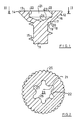
- the countersunk screw contains a screw shaft 11 which merges into a countersunk head 12 in the region of the one end of the screw provided with a drive.
- the countersunk head 12 is delimited by a flat end surface 13.
- the end face 13 is followed by a very short cylindrical section 14.
- the screw shaft 11 is provided with circumferential thread 15.
- the thread is formed right up to the underside of the countersunk head 12. It is made by rolling.
- the countersunk head 12 contains a section 16 immediately following the flat cylindrical section 14, in which the outside or underside of the countersunk head 12 lies in a truncated cone surface.
- the edge of this section 16 lying in the cross section of the figure encloses an angle of approximately 45 ° or otherwise with the longitudinal axis of the screw expressed, the end edges of section 16 visible in section run at a right angle to one another.
- a second section 18 adjoins the first section 16 of the countersunk head, in which the underside or outer surface of the countersunk head 12 lies on a significantly flatter truncated cone.
- the edges of this second section 18 visible in section each run at an angle of approximately 76 ° with respect to the longitudinal axis of the screw.
- This second section 18 merges directly into the threaded shaft 11 via a further edge 19.
- the edges 17 and 19 are rounded.
- the thread 15 rolled on the shaft 11 can reach much closer to the underside of the countersunk head 12 or also closer to the end face 13 of the screw.
- the recesses 21 has one for the transmission of torques the screw head has a non-circular outer shape.
- the recess 21 can be a hexagon recess.
- the recess 21 has side faces 22 which run approximately parallel to one another and to the longitudinal axis of the screw.
- the side surfaces 22 can diverge slightly, for example in a range of 2 °.
- the bottom 23 of the recess 21 is made relatively flat, for example it has a tip angle 24 of approximately 135 ° -140 °.
- An outer shape of the recess 21 is particularly preferred, in which six concave and six convex arcs alternate in succession, the transitions of which are smooth. With such a recess high torques can be transmitted so that the relatively small depth of the recess 21 is sufficient for the screw.
- region 18 is formed by a truncated cone surface, it could also be somewhat rounded overall, that is to say correspond approximately to a spherical surface.
- Fig. 2 now shows a cross section through the screw of Fig. 1 somewhat along the line II-II.
- the mentioned shape of the recess 21 can be seen from this cross section.
- the recess 21 is formed by side surfaces 22, which are composed of six concave and six convex circular arc-shaped curvatures.
- six arches 26 facing inwards and six arches 27 facing outwards are formed.
- the outwardly facing arches 27 have approximately half the radius as the inwardly facing arches 26.
- Such a shape of the recess 21 is particularly favorable for the transmission of high torques, so that it is preferred.
- the screw has 16 ribs 25 on the underside of its screw head in the region of the first conical section, which are close to one another and are approximately semicircular in cross section.
- the longitudinal axes of the ribs 25 intersect the longitudinal axis of the screw shaft 11.
- the ribs 25 on the underside of the screw head form a securing means for the screw that is tightened, which prevents the screw from being unintentionally loosened, for example in the event of vibrations.
- the ribs 25 can be molded in the same operation in the manufacture of the screw, so that no additional effort is required. It has proven to be particularly useful if there are about 12 to 20 ribs 25.
- the screw has a flat upper side 13.
- this upper side or end face 13 may be slightly curved, as is the case with conventional oval head screws. Raised-head screws should also fall under the term countersunk screw used by the invention.
- the underside of the countersunk head 12 lies in the second section 18 on a flat truncated cone with an apex angle of approximately 150 °. This angle is somewhat larger than the apex angle 24 of the base 23 of the recess 21. In the extreme case, the flatter region 18 can also be designed so flat that it approaches a plane.
Landscapes
- Engineering & Computer Science (AREA)
- General Engineering & Computer Science (AREA)
- Mechanical Engineering (AREA)
- Extrusion Moulding Of Plastics Or The Like (AREA)
- Connection Of Plates (AREA)
Applications Claiming Priority (2)
| Application Number | Priority Date | Filing Date | Title |
|---|---|---|---|
| DE3923091 | 1989-07-13 | ||
| DE19893923091 DE3923091A1 (de) | 1989-07-13 | 1989-07-13 | Senkkopfschraube |
Publications (2)
| Publication Number | Publication Date |
|---|---|
| EP0407856A2 true EP0407856A2 (fr) | 1991-01-16 |
| EP0407856A3 EP0407856A3 (en) | 1991-08-07 |
Family
ID=6384908
Family Applications (1)
| Application Number | Title | Priority Date | Filing Date |
|---|---|---|---|
| EP19900112648 Withdrawn EP0407856A3 (en) | 1989-07-13 | 1990-07-03 | Countersunk head screw |
Country Status (2)
| Country | Link |
|---|---|
| EP (1) | EP0407856A3 (fr) |
| DE (1) | DE3923091A1 (fr) |
Cited By (3)
| Publication number | Priority date | Publication date | Assignee | Title |
|---|---|---|---|---|
| EP0558831A1 (fr) * | 1992-03-05 | 1993-09-08 | Gebu Draadwarenfabriek Ing H.G. Geist B.V. | Vis ou boulon à vis |
| US5516173A (en) * | 1993-03-15 | 1996-05-14 | Btm Corporation | Gripper |
| US20210246928A1 (en) * | 2020-02-11 | 2021-08-12 | Carl Chasse | Fastener having improved wobble control, fastening system including the same, and method of forming the same |
Families Citing this family (1)
| Publication number | Priority date | Publication date | Assignee | Title |
|---|---|---|---|---|
| DE10061559A1 (de) † | 2000-12-07 | 2002-06-13 | C & E Fein Gmbh & Co Kg | Aufnahme zur Befestigung eines Werkzeuges an einer Antriebswelle und Adapter hierzu |
Citations (6)
| Publication number | Priority date | Publication date | Assignee | Title |
|---|---|---|---|---|
| US2982166A (en) * | 1958-07-24 | 1961-05-02 | Robert W Hobbs | Fastener head the underlying surface of which has means to smooth the workpiece surface |
| US3178984A (en) * | 1963-02-01 | 1965-04-20 | Charles F Barothy | Screw dowel |
| FR2127519A5 (fr) * | 1971-02-22 | 1972-10-13 | Hettich Paul & Co | |
| US3849964A (en) * | 1973-08-15 | 1974-11-26 | F Briles | Corrosion blocking fastener |
| DE2545581A1 (de) * | 1975-09-16 | 1977-04-14 | Textron Inc | Selbststauchender befestiger |
| US4111580A (en) * | 1976-12-30 | 1978-09-05 | The Boeing Company | Continuously curved fastener head and countersink have interference fit |
Family Cites Families (6)
| Publication number | Priority date | Publication date | Assignee | Title |
|---|---|---|---|---|
| US3255797A (en) * | 1964-06-15 | 1966-06-14 | Warren R Attwood | Structural assemblies |
| NL128843C (fr) * | 1965-07-28 | |||
| NL6710350A (fr) * | 1966-09-19 | 1968-03-20 | ||
| DE7106600U (de) * | 1971-02-22 | 1975-07-10 | Hettich P & Co | Senkschraube zum Verbinden eines starren Beschlagteils mit einem Kunststoffteil |
| DE2260443A1 (de) * | 1972-12-11 | 1974-06-12 | Schnegelsiepen & Wesser Fasson | Schraube oder huelsenschraube |
| DE3531376A1 (de) * | 1985-09-03 | 1987-05-21 | Wieland Werke Ag | Eck- oder stossverbindung zweier hohlprofile fuer fenster-, tuerrahmen od. dgl. |
-
1989
- 1989-07-13 DE DE19893923091 patent/DE3923091A1/de not_active Withdrawn
-
1990
- 1990-07-03 EP EP19900112648 patent/EP0407856A3/de not_active Withdrawn
Patent Citations (6)
| Publication number | Priority date | Publication date | Assignee | Title |
|---|---|---|---|---|
| US2982166A (en) * | 1958-07-24 | 1961-05-02 | Robert W Hobbs | Fastener head the underlying surface of which has means to smooth the workpiece surface |
| US3178984A (en) * | 1963-02-01 | 1965-04-20 | Charles F Barothy | Screw dowel |
| FR2127519A5 (fr) * | 1971-02-22 | 1972-10-13 | Hettich Paul & Co | |
| US3849964A (en) * | 1973-08-15 | 1974-11-26 | F Briles | Corrosion blocking fastener |
| DE2545581A1 (de) * | 1975-09-16 | 1977-04-14 | Textron Inc | Selbststauchender befestiger |
| US4111580A (en) * | 1976-12-30 | 1978-09-05 | The Boeing Company | Continuously curved fastener head and countersink have interference fit |
Cited By (4)
| Publication number | Priority date | Publication date | Assignee | Title |
|---|---|---|---|---|
| EP0558831A1 (fr) * | 1992-03-05 | 1993-09-08 | Gebu Draadwarenfabriek Ing H.G. Geist B.V. | Vis ou boulon à vis |
| US5516173A (en) * | 1993-03-15 | 1996-05-14 | Btm Corporation | Gripper |
| US5647625A (en) * | 1993-03-15 | 1997-07-15 | Btm Corporation | Gripper |
| US20210246928A1 (en) * | 2020-02-11 | 2021-08-12 | Carl Chasse | Fastener having improved wobble control, fastening system including the same, and method of forming the same |
Also Published As
| Publication number | Publication date |
|---|---|
| EP0407856A3 (en) | 1991-08-07 |
| DE3923091A1 (de) | 1991-01-24 |
Similar Documents
| Publication | Publication Date | Title |
|---|---|---|
| EP0869287B1 (fr) | Elément de fixation autopoinçonneur et autotaraudeur | |
| EP2310697B1 (fr) | Vis | |
| EP0464071B1 (fr) | Vis autotaraudeuse | |
| EP2521864B1 (fr) | Vis auto-taraudante et son utilisation | |
| EP2021639B1 (fr) | Vis autoperceuse | |
| EP0212068B1 (fr) | Clou avec une tête à un bout de la tige et une pointe à l'autre | |
| DE3909725C1 (en) | Hole- and thread-forming screw | |
| WO2005080802A1 (fr) | Vis autotaraudeuse | |
| EP1031741A1 (fr) | Vis à tête conique | |
| DE1400229B1 (de) | Selbstgewindeherstellende Schraube | |
| EP0524617A1 (fr) | Configuration d'entraînement de tête de vis | |
| EP1718876A1 (fr) | Vis autotaraudeuse | |
| WO2009109383A1 (fr) | Élément de fixation | |
| EP0939235B1 (fr) | Vis | |
| EP1031742A1 (fr) | Vis à tête conique | |
| WO2000061959A1 (fr) | Vis a tete fraisee | |
| DE4444467A1 (de) | Gewindeschneidschraube | |
| EP2150709B1 (fr) | Vis pour panneaux de particules | |
| EP0447902B1 (fr) | Vis pour fixer des plaques de pavement en plâte | |
| WO1999011436A1 (fr) | Profile de transmission de force, notamment outil polygonal de manoeuvre des vis et ecrous | |
| EP0257664A1 (fr) | Commande intérieure, chape et tournevis pour une vis universelle | |
| EP0407856A2 (fr) | Vis à tête conique | |
| DE4108771A1 (de) | Spanplattenschraube | |
| DE102006023025A1 (de) | Schnellbau - Kopfgeometrie | |
| EP0532990A2 (fr) | Vis autotarandeuse, procédé pour sa fabrication et matrices de laminage pour la mise en oeuvre du procédé |
Legal Events
| Date | Code | Title | Description |
|---|---|---|---|
| PUAI | Public reference made under article 153(3) epc to a published international application that has entered the european phase |
Free format text: ORIGINAL CODE: 0009012 |
|
| AK | Designated contracting states |
Kind code of ref document: A2 Designated state(s): AT BE CH DE DK ES FR GB GR IT LI LU NL SE |
|
| PUAL | Search report despatched |
Free format text: ORIGINAL CODE: 0009013 |
|
| AK | Designated contracting states |
Kind code of ref document: A3 Designated state(s): AT BE CH DE DK ES FR GB GR IT LI LU NL SE |
|
| STAA | Information on the status of an ep patent application or granted ep patent |
Free format text: STATUS: THE APPLICATION IS DEEMED TO BE WITHDRAWN |
|
| 18D | Application deemed to be withdrawn |
Effective date: 19920208 |