EP0406185A2 - Fluid bed furnace - Google Patents
Fluid bed furnace Download PDFInfo
- Publication number
- EP0406185A2 EP0406185A2 EP90850181A EP90850181A EP0406185A2 EP 0406185 A2 EP0406185 A2 EP 0406185A2 EP 90850181 A EP90850181 A EP 90850181A EP 90850181 A EP90850181 A EP 90850181A EP 0406185 A2 EP0406185 A2 EP 0406185A2
- Authority
- EP
- European Patent Office
- Prior art keywords
- combustion
- passage
- particle separator
- gases
- convection heating
- Prior art date
- Legal status (The legal status is an assumption and is not a legal conclusion. Google has not performed a legal analysis and makes no representation as to the accuracy of the status listed.)
- Granted
Links
Images

Classifications
-
- F—MECHANICAL ENGINEERING; LIGHTING; HEATING; WEAPONS; BLASTING
- F27—FURNACES; KILNS; OVENS; RETORTS
- F27B—FURNACES, KILNS, OVENS, OR RETORTS IN GENERAL; OPEN SINTERING OR LIKE APPARATUS
- F27B15/00—Fluidised-bed furnaces; Other furnaces using or treating finely-divided materials in dispersion
-
- F—MECHANICAL ENGINEERING; LIGHTING; HEATING; WEAPONS; BLASTING
- F23—COMBUSTION APPARATUS; COMBUSTION PROCESSES
- F23C—METHODS OR APPARATUS FOR COMBUSTION USING FLUID FUEL OR SOLID FUEL SUSPENDED IN A CARRIER GAS OR AIR
- F23C10/00—Fluidised bed combustion apparatus
- F23C10/02—Fluidised bed combustion apparatus with means specially adapted for achieving or promoting a circulating movement of particles within the bed or for a recirculation of particles entrained from the bed
- F23C10/04—Fluidised bed combustion apparatus with means specially adapted for achieving or promoting a circulating movement of particles within the bed or for a recirculation of particles entrained from the bed the particles being circulated to a section, e.g. a heat-exchange section or a return duct, at least partially shielded from the combustion zone, before being reintroduced into the combustion zone
- F23C10/08—Fluidised bed combustion apparatus with means specially adapted for achieving or promoting a circulating movement of particles within the bed or for a recirculation of particles entrained from the bed the particles being circulated to a section, e.g. a heat-exchange section or a return duct, at least partially shielded from the combustion zone, before being reintroduced into the combustion zone characterised by the arrangement of separation apparatus, e.g. cyclones, for separating particles from the flue gases
- F23C10/10—Fluidised bed combustion apparatus with means specially adapted for achieving or promoting a circulating movement of particles within the bed or for a recirculation of particles entrained from the bed the particles being circulated to a section, e.g. a heat-exchange section or a return duct, at least partially shielded from the combustion zone, before being reintroduced into the combustion zone characterised by the arrangement of separation apparatus, e.g. cyclones, for separating particles from the flue gases the separation apparatus being located outside the combustion chamber
-
- F—MECHANICAL ENGINEERING; LIGHTING; HEATING; WEAPONS; BLASTING
- F23—COMBUSTION APPARATUS; COMBUSTION PROCESSES
- F23J—REMOVAL OR TREATMENT OF COMBUSTION PRODUCTS OR COMBUSTION RESIDUES; FLUES
- F23J15/00—Arrangements of devices for treating smoke or fumes
- F23J15/08—Arrangements of devices for treating smoke or fumes of heaters
-
- F—MECHANICAL ENGINEERING; LIGHTING; HEATING; WEAPONS; BLASTING
- F27—FURNACES; KILNS; OVENS; RETORTS
- F27D—DETAILS OR ACCESSORIES OF FURNACES, KILNS, OVENS, OR RETORTS, IN SO FAR AS THEY ARE OF KINDS OCCURRING IN MORE THAN ONE KIND OF FURNACE
- F27D17/00—Arrangements for using waste heat; Arrangements for using, or disposing of, waste gases
- F27D17/004—Systems for reclaiming waste heat
-
- F—MECHANICAL ENGINEERING; LIGHTING; HEATING; WEAPONS; BLASTING
- F23—COMBUSTION APPARATUS; COMBUSTION PROCESSES
- F23C—METHODS OR APPARATUS FOR COMBUSTION USING FLUID FUEL OR SOLID FUEL SUSPENDED IN A CARRIER GAS OR AIR
- F23C2206/00—Fluidised bed combustion
- F23C2206/10—Circulating fluidised bed
- F23C2206/101—Entrained or fast fluidised bed
-
- F—MECHANICAL ENGINEERING; LIGHTING; HEATING; WEAPONS; BLASTING
- F23—COMBUSTION APPARATUS; COMBUSTION PROCESSES
- F23J—REMOVAL OR TREATMENT OF COMBUSTION PRODUCTS OR COMBUSTION RESIDUES; FLUES
- F23J2215/00—Preventing emissions
- F23J2215/10—Nitrogen; Compounds thereof
- F23J2215/101—Nitrous oxide (N2O)
Definitions
- the object of the present invention is to propose a device for the destruction of such gaseous emissions, which will occur during combustion at comparatively moderate temperatures in a fluid bed furnace.
- the invention thus refers to a fluid bed furnace comprising a furnace shaft and a particle separator as well as convection heating surfaces in a combustion gas conduit downstream of the particle separator and is characterized by that the combustion gas conduit between the gas outlet from the particle separator and the convection heating surfaces is designed as a reactor passage, that at least one combustion means is located at the upstream end thereof, and that the reactor passage is moderately cooled in such a manner that the increase of temperature in the combustion gases caused by the combustion means is maintained substantially constant unto the first convection heating surface.
- the combustion means may be located at the upstream end of the reactor passage.
- a gas mixing device is then preferably located in the reactor passage, adjacent to the combustion means.
- the combustion means is adapted for burning solid fuel, such as sawdust, pellets of bio-mass or the like
- the combustion means is preferably located adjacent to the entrance to the particle separator, whereby ashes and solid combustion residues will be caught.
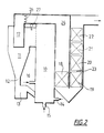
- the CFB-boiler shown in Fig. 1 comprises a combustion shaft 10, a particle separator 11, preferably of the cyclone type, and a conduit 12 for returning separated particles to the combustion shaft 10.
- the return conduit is provided with a particle lock 13, which makes it possible to control the return flow of particles.
- Fuel is supplied by way of a conduit 14, primary combustion air by way of a conduit 15 and secondary air by way of a conduit 16.
- Inert bed material, and possibly also a sulphur reduction material may be added to the fuel and be supplies by way of conduit 14, but may alternatively be supplied by a separate conduit (not shown). Combustion residues may be removed from the lower part of the combustion shaft 10, or from the particle lock 13.
- the combustion shaft is designed in the conventional manner, and is provided with satisfactory cooling, for instance by means of tube panels in the walls.
- the fuel and the inert bed material may be maintained in suspended state in the combustion shaft and is burnt at a moderate temperature of about 850°C.
- a certain amount of solid material is carried over to the particle separator 11. The particles separated out will be returned to the combustion shaft, and the combustion gases will pass out through an outlet 17.
- a number of convection heating surfaces 18-22 are, in a conventional manner, arranged in the combustion gas flue 23 downstream of the particle separator 11.
- a reaction passage 24 extends between the latter and the foremost convection heating surface 18, and a combustion means 25, for instance burning oil or gas, is located in the entrance part of the reaction passage.
- a gas mixing device 26 is preferably arranged adjacent to the combustion means.
- the reactor passage 24 is in the schematic drawing shown with double lines.
- N2O laughing gas
- Laughing gas may, in small doses, have certain pharmaceutical applications, but the amounts actual during combustion will be environmentally disturbing. This gas has i.a. a negative influence upon the ozon layer in space, and big outlets are not acceptable.
- N2O For the destruction of N2O a temperature of 900 - 1 100°C is needed.
- the N2O-content in the combustion gases may vary depending upon the kind of fuel used, and the destruction takes some time.
- the length of the reactor passage 24 is selected in such a manner that it will take up to 5 seconds for the gases to pass the passage at normal load upon the boiler.
- the laughing gas (N2O) will by the destruction mainly be transferred into nitrogene, N2,which is normally present in the ambient air.
- the reactor passage 24 is insulated and is only moderately cooled in order to prevent damages, so the increase in temperature caused by the additional combustion means 25 is maintained substantially constant up to the first convection heating surface 18.
- the combustion means may comprise one or more additional fuel burners, or include a device for deferred combustion (i.e. final combustion outside the combustion shaft).
Abstract
Description
- When burning solid fuel in a fluid bed furnace the temperature is usually maintained at a moderate level of about 850°C. In this manner a sinterning of the fuel residues is prevented, and the risk of generating certain obnoxious emissions, especially nitrogene oxide, NOx, is reduced,. An increase of other environmentally harmful emissions, for instance N₂O (laughing gas) may instead be brought about. This is especially noticeable when burning bio-mass fuels.
- The object of the present invention is to propose a device for the destruction of such gaseous emissions, which will occur during combustion at comparatively moderate temperatures in a fluid bed furnace.
- The invention thus refers to a fluid bed furnace comprising a furnace shaft and a particle separator as well as convection heating surfaces in a combustion gas conduit downstream of the particle separator and is characterized by that the combustion gas conduit between the gas outlet from the particle separator and the convection heating surfaces is designed as a reactor passage, that at least one combustion means is located at the upstream end thereof, and that the reactor passage is moderately cooled in such a manner that the increase of temperature in the combustion gases caused by the combustion means is maintained substantially constant unto the first convection heating surface.
- The combustion means may be located at the upstream end of the reactor passage. A gas mixing device is then preferably located in the reactor passage, adjacent to the combustion means.
- When the combustion means is adapted for burning solid fuel, such as sawdust, pellets of bio-mass or the like, the combustion means is preferably located adjacent to the entrance to the particle separator, whereby ashes and solid combustion residues will be caught.
- The invention will below be described with reference to the accompanying drawings which schematically shows boilers having furnaces operating according to the circulating fluid bed principle (CFB).
- The CFB-boiler shown in Fig. 1 comprises a
combustion shaft 10, aparticle separator 11, preferably of the cyclone type, and aconduit 12 for returning separated particles to thecombustion shaft 10. The return conduit is provided with aparticle lock 13, which makes it possible to control the return flow of particles. Fuel is supplied by way of aconduit 14, primary combustion air by way of aconduit 15 and secondary air by way of aconduit 16. Inert bed material, and possibly also a sulphur reduction material may be added to the fuel and be supplies by way ofconduit 14, but may alternatively be supplied by a separate conduit (not shown). Combustion residues may be removed from the lower part of thecombustion shaft 10, or from theparticle lock 13. - The combustion shaft is designed in the conventional manner, and is provided with satisfactory cooling, for instance by means of tube panels in the walls. By controlling the supply of primary and secondary air, the fuel and the inert bed material may be maintained in suspended state in the combustion shaft and is burnt at a moderate temperature of about 850°C. A certain amount of solid material is carried over to the
particle separator 11. The particles separated out will be returned to the combustion shaft, and the combustion gases will pass out through anoutlet 17. - A number of convection heating surfaces 18-22 are, in a conventional manner, arranged in the
combustion gas flue 23 downstream of theparticle separator 11. Areaction passage 24 extends between the latter and the foremostconvection heating surface 18, and a combustion means 25, for instance burning oil or gas, is located in the entrance part of the reaction passage. Agas mixing device 26 is preferably arranged adjacent to the combustion means. - The
reactor passage 24 is in the schematic drawing shown with double lines. By monitoring the combustion in theshaft 11 so a temperature of about 850°C is maintained the generation of nitrous oxides NOx is largely prevented, but instead a risk of obtaining a considerable amount of laughing gas (N₂O) is met. Laughing gas may, in small doses, have certain pharmaceutical applications, but the amounts actual during combustion will be environmentally disturbing. This gas has i.a. a negative influence upon the ozon layer in space, and big outlets are not acceptable. - For the destruction of N₂O a temperature of 900 - 1 100°C is needed. The N₂O-content in the combustion gases may vary depending upon the kind of fuel used, and the destruction takes some time. The length of the
reactor passage 24 is selected in such a manner that it will take up to 5 seconds for the gases to pass the passage at normal load upon the boiler. The laughing gas (N₂O) will by the destruction mainly be transferred into nitrogene, N₂,which is normally present in the ambient air. - The
reactor passage 24 is insulated and is only moderately cooled in order to prevent damages, so the increase in temperature caused by the additional combustion means 25 is maintained substantially constant up to the firstconvection heating surface 18. For practical reasons it may be advantageous to interconnect the convection heating surfaces, with the cooling surfaces in the combustion shaft by means of piping passing the walls of the reactor passage, and in such case an extra insulation of the passage is provided. - The embodiment described above and shown in the drawing are examples only of the invention, the details of which may be varied in many ways within the scope of the appended claims, and depending upon the required output, and the type of fuel used. Beside with the CFB-type furnaces shown, the invention, may be used with other kinds of fluid bed furnaces, or other furnaces where the laughing gas content in the combustion gases should be reduced.
- The combustion means may comprise one or more additional fuel burners, or include a device for deferred combustion (i.e. final combustion outside the combustion shaft).
Claims (5)
Applications Claiming Priority (2)
| Application Number | Priority Date | Filing Date | Title |
|---|---|---|---|
| SE8901980A SE466814B (en) | 1989-06-01 | 1989-06-01 | DEVICE FOR DEGRADATION OF GASES GENERATED FOR PRESENT BURNING AT UNGEFER 850 DEGREES C OF THE SOLID BROWN IN A LIQUID BED |
| SE8901980 | 1989-06-01 |
Publications (3)
| Publication Number | Publication Date |
|---|---|
| EP0406185A2 true EP0406185A2 (en) | 1991-01-02 |
| EP0406185A3 EP0406185A3 (en) | 1991-05-08 |
| EP0406185B1 EP0406185B1 (en) | 1994-01-26 |
Family
ID=20376142
Family Applications (1)
| Application Number | Title | Priority Date | Filing Date |
|---|---|---|---|
| EP90850181A Expired - Lifetime EP0406185B1 (en) | 1989-06-01 | 1990-05-17 | Fluid bed furnace |
Country Status (6)
| Country | Link |
|---|---|
| US (1) | US5103773A (en) |
| EP (1) | EP0406185B1 (en) |
| DK (1) | DK0406185T3 (en) |
| ES (1) | ES2051502T3 (en) |
| NO (1) | NO175669C (en) |
| SE (1) | SE466814B (en) |
Cited By (9)
| Publication number | Priority date | Publication date | Assignee | Title |
|---|---|---|---|---|
| US5043150A (en) * | 1990-04-17 | 1991-08-27 | A. Ahlstrom Corporation | Reducing emissions of N2 O when burning nitrogen containing fuels in fluidized bed reactors |
| BE1003586A3 (en) * | 1989-09-29 | 1992-04-28 | Hillebrand Rudolf Gmbh | Four fluidized bed. |
| FR2682459A1 (en) * | 1991-10-09 | 1993-04-16 | Stein Industrie | Method and devices for decreasing the nitrogen monoxide content of the gases from an oxidising combustion of a fluidised-bed reactor |
| WO1993017281A1 (en) * | 1992-02-19 | 1993-09-02 | Wiser Oy | A METHOD FOR REMOVING NOx GASES FROM FLUE GASES |
| EP0564550A1 (en) * | 1990-12-27 | 1993-10-13 | Nalco Fuel Tech | Process and apparatus for the thermal decomposition of nitrous oxide |
| WO1994027716A1 (en) * | 1993-06-01 | 1994-12-08 | A. Ahlstrom Corporation | Circulating fluidized bed reactor and method of treating gas flows in the circulating fluidized bed reactor |
| EP0851173A2 (en) | 1996-12-30 | 1998-07-01 | Combustion Engineering, Inc. | A method of controlling nitrous oxide in circulating fluidized bed steam generators |
| FR2871554A1 (en) * | 2004-06-11 | 2005-12-16 | Alstom Technology Ltd | METHOD FOR THE ENERGY CONVERSION OF SOLID FUELS MINIMIZING OXYGEN CONSUMPTION |
| WO2006134134A1 (en) * | 2005-06-15 | 2006-12-21 | Alstom Technology Ltd | A circulating fluidized bed device provided with an oxygen-fired furnace |
Families Citing this family (11)
| Publication number | Priority date | Publication date | Assignee | Title |
|---|---|---|---|---|
| US5133950A (en) * | 1990-04-17 | 1992-07-28 | A. Ahlstrom Corporation | Reducing N2 O emissions when burning nitrogen-containing fuels in fluidized bed reactors |
| SE501158C2 (en) * | 1992-04-16 | 1994-11-28 | Flaekt Ab | Ways to clean flue gases with a deficit of oxygen and formed soot |
| SE470222B (en) * | 1992-05-05 | 1993-12-06 | Abb Carbon Ab | Procedure for maintaining nominal working temperature of the flue gases in a PFBC power plant |
| US5634329A (en) * | 1992-04-30 | 1997-06-03 | Abb Carbon Ab | Method of maintaining a nominal working temperature of flue gases in a PFBC power plant |
| CA2105602A1 (en) * | 1993-09-07 | 1995-03-08 | Ola Herstad | Steam boiler |
| US5755187A (en) * | 1993-09-08 | 1998-05-26 | Gotaverken Energy Ab | Steam boiler with externally positioned superheating means |
| US5378253A (en) * | 1993-09-28 | 1995-01-03 | The Babcock & Wilcox Company | Water/steam-cooled U-beam impact type article separator |
| SE9402789L (en) * | 1994-08-19 | 1995-10-02 | Kvaerner Enviropower Ab | Method for two-stage combustion of solid fuels in a circulating fluidized bed |
| FR2775061B1 (en) * | 1998-02-16 | 2000-03-10 | Gec Alsthom Stein Ind | CIRCULATING FLUIDIZED BED BOILER WITH IMPROVED NITROGEN OXIDE REDUCTION |
| FI114737B (en) * | 2002-04-24 | 2004-12-15 | Tom Blomberg | Procedure for placing steam superheaters in steam boilers that burn biomass and steam boiler |
| US7244400B2 (en) | 2003-11-25 | 2007-07-17 | Foster Wheeler Energy Corporation | Fluidized bed reactor system having an exhaust gas plenum |
Citations (2)
| Publication number | Priority date | Publication date | Assignee | Title |
|---|---|---|---|---|
| US4111158A (en) * | 1976-05-31 | 1978-09-05 | Metallgesellschaft Aktiengesellschaft | Method of and apparatus for carrying out an exothermic process |
| US4128392A (en) * | 1975-08-11 | 1978-12-05 | Fuller Company | Calciner for fine limestone |
Family Cites Families (9)
| Publication number | Priority date | Publication date | Assignee | Title |
|---|---|---|---|---|
| US3656440A (en) * | 1970-10-26 | 1972-04-18 | Morse Boulger Inc | Incinerator having means for treating combustion gases |
| US4531462A (en) * | 1980-01-18 | 1985-07-30 | University Of Kentucky Research Foundation | Biomass gasifier combustor |
| GB2167543B (en) * | 1984-11-26 | 1988-09-21 | Sanden Corp | Refrigerated display cabinet |
| FI850372A0 (en) * | 1985-01-29 | 1985-01-29 | Ahlstroem Oy | PANNA MED CIRKULERANDE BAEDD. |
| DE3525676A1 (en) * | 1985-07-18 | 1987-01-22 | Kraftwerk Union Ag | STEAM GENERATOR |
| US4622904A (en) * | 1985-12-13 | 1986-11-18 | The Babcock & Wilcox Company | Combined fluidized bed calciner and pulverized coal boiler and method of operation |
| DE3625992A1 (en) * | 1986-07-31 | 1988-02-04 | Steinmueller Gmbh L & C | METHOD FOR BURNING CARBON-CONTAINING MATERIALS IN A CIRCULATING FLUID BED, AND A FLUET BURNING PLANT FOR CARRYING OUT THE METHOD |
| US4827723A (en) * | 1988-02-18 | 1989-05-09 | A. Ahlstrom Corporation | Integrated gas turbine power generation system and process |
| US4936770A (en) * | 1988-11-25 | 1990-06-26 | Foster Wheeler Energy Corporation | Sulfur sorbent feed system for a fluidized bed reactor |
-
1989
- 1989-06-01 SE SE8901980A patent/SE466814B/en not_active IP Right Cessation
-
1990
- 1990-05-17 DK DK90850181.0T patent/DK0406185T3/en active
- 1990-05-17 EP EP90850181A patent/EP0406185B1/en not_active Expired - Lifetime
- 1990-05-17 ES ES90850181T patent/ES2051502T3/en not_active Expired - Lifetime
- 1990-05-31 NO NO902413A patent/NO175669C/en not_active IP Right Cessation
-
1991
- 1991-04-26 US US07/690,321 patent/US5103773A/en not_active Expired - Lifetime
Patent Citations (2)
| Publication number | Priority date | Publication date | Assignee | Title |
|---|---|---|---|---|
| US4128392A (en) * | 1975-08-11 | 1978-12-05 | Fuller Company | Calciner for fine limestone |
| US4111158A (en) * | 1976-05-31 | 1978-09-05 | Metallgesellschaft Aktiengesellschaft | Method of and apparatus for carrying out an exothermic process |
Cited By (16)
| Publication number | Priority date | Publication date | Assignee | Title |
|---|---|---|---|---|
| BE1003586A3 (en) * | 1989-09-29 | 1992-04-28 | Hillebrand Rudolf Gmbh | Four fluidized bed. |
| US5043150A (en) * | 1990-04-17 | 1991-08-27 | A. Ahlstrom Corporation | Reducing emissions of N2 O when burning nitrogen containing fuels in fluidized bed reactors |
| EP0564550A1 (en) * | 1990-12-27 | 1993-10-13 | Nalco Fuel Tech | Process and apparatus for the thermal decomposition of nitrous oxide |
| EP0564550A4 (en) * | 1990-12-27 | 1993-12-29 | Nalco Fuel Tech | Process and apparatus for the thermal decomposition of nitrous oxide |
| FR2682459A1 (en) * | 1991-10-09 | 1993-04-16 | Stein Industrie | Method and devices for decreasing the nitrogen monoxide content of the gases from an oxidising combustion of a fluidised-bed reactor |
| WO1993017281A1 (en) * | 1992-02-19 | 1993-09-02 | Wiser Oy | A METHOD FOR REMOVING NOx GASES FROM FLUE GASES |
| WO1994027716A1 (en) * | 1993-06-01 | 1994-12-08 | A. Ahlstrom Corporation | Circulating fluidized bed reactor and method of treating gas flows in the circulating fluidized bed reactor |
| EP0851173A2 (en) | 1996-12-30 | 1998-07-01 | Combustion Engineering, Inc. | A method of controlling nitrous oxide in circulating fluidized bed steam generators |
| FR2871554A1 (en) * | 2004-06-11 | 2005-12-16 | Alstom Technology Ltd | METHOD FOR THE ENERGY CONVERSION OF SOLID FUELS MINIMIZING OXYGEN CONSUMPTION |
| WO2005124232A1 (en) * | 2004-06-11 | 2005-12-29 | Alstom Technology Ltd | Method for energy conversion minimizing oxygen consumption |
| US7820139B2 (en) | 2004-06-11 | 2010-10-26 | Alstom Technology Ltd | Method for energy conversion minimizing oxygen consumption |
| CN1969150B (en) * | 2004-06-11 | 2011-01-26 | 阿尔斯托姆科技有限公司 | Method for energy conversion minimizing oxygen consumption |
| WO2006134134A1 (en) * | 2005-06-15 | 2006-12-21 | Alstom Technology Ltd | A circulating fluidized bed device provided with an oxygen-fired furnace |
| FR2887322A1 (en) * | 2005-06-15 | 2006-12-22 | Alstom Technology Ltd | CIRCULATING FLUIDIZED BED DEVICE WITH OXYGEN COMBUSTION FIREPLACE |
| CN101198821B (en) * | 2005-06-15 | 2010-10-13 | 阿尔斯托姆科技有限公司 | A circulating fluidized bed device provided with an oxygen-fired furnace |
| US8230795B2 (en) | 2005-06-15 | 2012-07-31 | Jean-Xavier Morin | Circulating fluidized bed device provided with an oxygen-fired furnace |
Also Published As
| Publication number | Publication date |
|---|---|
| NO175669B (en) | 1994-08-08 |
| EP0406185A3 (en) | 1991-05-08 |
| DK0406185T3 (en) | 1994-05-24 |
| US5103773A (en) | 1992-04-14 |
| EP0406185B1 (en) | 1994-01-26 |
| NO175669C (en) | 1994-11-16 |
| SE466814B (en) | 1992-04-06 |
| ES2051502T3 (en) | 1994-06-16 |
| SE8901980D0 (en) | 1989-06-01 |
| SE8901980L (en) | 1990-12-02 |
| NO902413D0 (en) | 1990-05-31 |
| NO902413L (en) | 1990-12-03 |
Similar Documents
| Publication | Publication Date | Title |
|---|---|---|
| EP0406185B1 (en) | Fluid bed furnace | |
| US5105747A (en) | Process and apparatus for reducing pollutant emissions in flue gases | |
| JPH05507140A (en) | Collective concentric angular combustion system | |
| CA2121295C (en) | Method for burning fuels, particularly for incinerating garbage | |
| US5762008A (en) | Burning fuels, particularly for incinerating garbage | |
| JPS5837415A (en) | Nox decreasing incinerator | |
| JPS6323442B2 (en) | ||
| CN106352343A (en) | Gasifying incinerator applicable to household garbage with high heat value | |
| EP0432293B1 (en) | Method for recovering waste gases from coal combustor | |
| EP0206340A2 (en) | Multi-bed fluid bed boiler | |
| US5311829A (en) | Method for reduction of sulfur oxides and particulates in coal combustion exhaust gases | |
| CA1290988C (en) | Method of combustion for fluidized bed incinerators | |
| RU2165051C2 (en) | Method of burning fossil fuel and wastes | |
| JPH05180413A (en) | Fluidized bed combustion boilers | |
| JP2642568B2 (en) | Secondary combustion method of refuse incinerator | |
| SU1733844A1 (en) | Boiler | |
| JP3508036B2 (en) | Boiler for circulating fluidized bed power generation | |
| JP3014953B2 (en) | Incinerator | |
| EP1500875A1 (en) | Method of operating waste incinerator and waste incinerator | |
| JP2518892B2 (en) | Structure of fluidized bed boiler | |
| JPS61205708A (en) | Re-burning method for unburnt residual in fluidized bed burning boiler | |
| Beshai et al. | Natural gas cofiring in a refuse derived fuel incinerator: results of a field evaluation | |
| KR960002798B1 (en) | Process for supplying combustion air and the furnace therefor | |
| JP2005282970A (en) | Combustion control method for stoker type garbage incinerator, and garbage incinerator | |
| JPH1114029A (en) | Circulating fluidized bed combustion equipment and method of operation |
Legal Events
| Date | Code | Title | Description |
|---|---|---|---|
| PUAI | Public reference made under article 153(3) epc to a published international application that has entered the european phase |
Free format text: ORIGINAL CODE: 0009012 |
|
| AK | Designated contracting states |
Kind code of ref document: A2 Designated state(s): DK ES FR GB SE |
|
| PUAL | Search report despatched |
Free format text: ORIGINAL CODE: 0009013 |
|
| AK | Designated contracting states |
Kind code of ref document: A3 Designated state(s): DK ES FR GB SE |
|
| 17P | Request for examination filed |
Effective date: 19910604 |
|
| RAP1 | Party data changed (applicant data changed or rights of an application transferred) |
Owner name: KVAERNER GENERATOR AB |
|
| 17Q | First examination report despatched |
Effective date: 19930413 |
|
| GRAA | (expected) grant |
Free format text: ORIGINAL CODE: 0009210 |
|
| AK | Designated contracting states |
Kind code of ref document: B1 Designated state(s): DK ES FR GB SE |
|
| RAP2 | Party data changed (patent owner data changed or rights of a patent transferred) |
Owner name: KVAERNER ENVIROPOWER AB |
|
| ET | Fr: translation filed | ||
| REG | Reference to a national code |
Ref country code: DK Ref legal event code: T3 |
|
| REG | Reference to a national code |
Ref country code: ES Ref legal event code: FG2A Ref document number: 2051502 Country of ref document: ES Kind code of ref document: T3 |
|
| PLBE | No opposition filed within time limit |
Free format text: ORIGINAL CODE: 0009261 |
|
| STAA | Information on the status of an ep patent application or granted ep patent |
Free format text: STATUS: NO OPPOSITION FILED WITHIN TIME LIMIT |
|
| 26N | No opposition filed | ||
| EAL | Se: european patent in force in sweden |
Ref document number: 90850181.0 |
|
| REG | Reference to a national code |
Ref country code: GB Ref legal event code: IF02 |
|
| REG | Reference to a national code |
Ref country code: GB Ref legal event code: 732E |
|
| REG | Reference to a national code |
Ref country code: ES Ref legal event code: PC2A |
|
| REG | Reference to a national code |
Ref country code: FR Ref legal event code: TP |
|
| REG | Reference to a national code |
Ref country code: FR Ref legal event code: CD |
|
| PGFP | Annual fee paid to national office [announced via postgrant information from national office to epo] |
Ref country code: DK Payment date: 20090513 Year of fee payment: 20 Ref country code: ES Payment date: 20090521 Year of fee payment: 20 |
|
| PGFP | Annual fee paid to national office [announced via postgrant information from national office to epo] |
Ref country code: FR Payment date: 20090513 Year of fee payment: 20 Ref country code: SE Payment date: 20090514 Year of fee payment: 20 |
|
| PGFP | Annual fee paid to national office [announced via postgrant information from national office to epo] |
Ref country code: GB Payment date: 20090522 Year of fee payment: 20 |
|
| REG | Reference to a national code |
Ref country code: DK Ref legal event code: EUP |
|
| EUG | Se: european patent has lapsed | ||
| REG | Reference to a national code |
Ref country code: ES Ref legal event code: FD2A Effective date: 20100518 |
|
| PG25 | Lapsed in a contracting state [announced via postgrant information from national office to epo] |
Ref country code: ES Free format text: LAPSE BECAUSE OF EXPIRATION OF PROTECTION Effective date: 20100518 |
|
| PG25 | Lapsed in a contracting state [announced via postgrant information from national office to epo] |
Ref country code: GB Free format text: LAPSE BECAUSE OF EXPIRATION OF PROTECTION Effective date: 20100516 |