EP0851173A2 - A method of controlling nitrous oxide in circulating fluidized bed steam generators - Google Patents
A method of controlling nitrous oxide in circulating fluidized bed steam generators Download PDFInfo
- Publication number
- EP0851173A2 EP0851173A2 EP97122925A EP97122925A EP0851173A2 EP 0851173 A2 EP0851173 A2 EP 0851173A2 EP 97122925 A EP97122925 A EP 97122925A EP 97122925 A EP97122925 A EP 97122925A EP 0851173 A2 EP0851173 A2 EP 0851173A2
- Authority
- EP
- European Patent Office
- Prior art keywords
- fluidized bed
- circulating fluidized
- steam generator
- bed steam
- emissions
- Prior art date
- Legal status (The legal status is an assumption and is not a legal conclusion. Google has not performed a legal analysis and makes no representation as to the accuracy of the status listed.)
- Granted
Links
Images
Classifications
-
- F—MECHANICAL ENGINEERING; LIGHTING; HEATING; WEAPONS; BLASTING
- F23—COMBUSTION APPARATUS; COMBUSTION PROCESSES
- F23C—METHODS OR APPARATUS FOR COMBUSTION USING FLUID FUEL OR SOLID FUEL SUSPENDED IN A CARRIER GAS OR AIR
- F23C10/00—Fluidised bed combustion apparatus
- F23C10/02—Fluidised bed combustion apparatus with means specially adapted for achieving or promoting a circulating movement of particles within the bed or for a recirculation of particles entrained from the bed
- F23C10/04—Fluidised bed combustion apparatus with means specially adapted for achieving or promoting a circulating movement of particles within the bed or for a recirculation of particles entrained from the bed the particles being circulated to a section, e.g. a heat-exchange section or a return duct, at least partially shielded from the combustion zone, before being reintroduced into the combustion zone
- F23C10/08—Fluidised bed combustion apparatus with means specially adapted for achieving or promoting a circulating movement of particles within the bed or for a recirculation of particles entrained from the bed the particles being circulated to a section, e.g. a heat-exchange section or a return duct, at least partially shielded from the combustion zone, before being reintroduced into the combustion zone characterised by the arrangement of separation apparatus, e.g. cyclones, for separating particles from the flue gases
- F23C10/10—Fluidised bed combustion apparatus with means specially adapted for achieving or promoting a circulating movement of particles within the bed or for a recirculation of particles entrained from the bed the particles being circulated to a section, e.g. a heat-exchange section or a return duct, at least partially shielded from the combustion zone, before being reintroduced into the combustion zone characterised by the arrangement of separation apparatus, e.g. cyclones, for separating particles from the flue gases the separation apparatus being located outside the combustion chamber
-
- F—MECHANICAL ENGINEERING; LIGHTING; HEATING; WEAPONS; BLASTING
- F23—COMBUSTION APPARATUS; COMBUSTION PROCESSES
- F23C—METHODS OR APPARATUS FOR COMBUSTION USING FLUID FUEL OR SOLID FUEL SUSPENDED IN A CARRIER GAS OR AIR
- F23C6/00—Combustion apparatus characterised by the combination of two or more combustion chambers or combustion zones, e.g. for staged combustion
- F23C6/04—Combustion apparatus characterised by the combination of two or more combustion chambers or combustion zones, e.g. for staged combustion in series connection
-
- F—MECHANICAL ENGINEERING; LIGHTING; HEATING; WEAPONS; BLASTING
- F23—COMBUSTION APPARATUS; COMBUSTION PROCESSES
- F23J—REMOVAL OR TREATMENT OF COMBUSTION PRODUCTS OR COMBUSTION RESIDUES; FLUES
- F23J2215/00—Preventing emissions
- F23J2215/10—Nitrogen; Compounds thereof
- F23J2215/101—Nitrous oxide (N2O)
Definitions
- This invention relates to fossil fuel-fired circulating fluidized bed steam generators (CFB), and more specifically to a method of controlling nitrous oxides in such fossil fuel-fired circulating fluidized bed steam generators (CFB) while concomitantly maintaining acceptable NO x and SO x emission levels therefrom.
- fluidization refers to the manner in which solid materials are provided with a free-flowing, fluid-like behavior.
- a gas is made to pass upwardly in a fluidized bed steam generator through a bed of solid particles that is present therewithin, such a flow of gases produces forces that tend to separate the solid particles one from another.
- fluidized bed steam generators are generally such that for purposes of the combustion process that takes place therewithin, fuel is burned in a bed of hot incombustible particles, the latter particles being suspended by an upwardly flow of fluidizing gas.
- this fluidizing gas normally is comprised of both air, which is being supplied to the fluidized bed steam generator to support the combustion of fuel therewithin, and the gaseous byproducts, which result from such combustion of fuel and air.
- Fluidized bed steam generators including but not limited to circulating fluidized bed steam generators (CFB), are normally intended to be operative to produce steam. Moreover, such production of steam results from the combustion of fuel and air within the fluidized bed steam generators. Furthermore, the steam that is so produced within the fluidized bed steam generator (CFB) is designed to be operative to function in accordance with a preselected thermodynamic steam cycle.
- CFB fluidized bed steam generator
- a circulating fluidized bed steam generator includes a furnace volume, the walls of which are comprised of vertical waterwall tubes.
- fuel and sorbent are mixed with and burned in air, producing hot combustion gases in which hot solids become entrained.
- heat is transferred to the aforementioned waterwall tubes thereby causing saturated steam to be evaporatively produced in conventional fashion from the water rising within the waterwall tubes.
- This saturated steam is a mix of steam and water, which is thereafter separated in known fashion in a steam drum. From the steam drum, the water is returned to the waterwall tubes in the lower segment of the furnace volume thereby completing an evaporative loop, while the steam is delivered to a superheater.
- the hot combustion gases and hot solids entrained therewithin are directed to a cyclone where unburned fuel, flyash and sorbent above a predetermined size are mechanically separated from the hot combustion gases.
- This unburned fuel, flyash and sorbent are collected from the cyclone, then are made to fall under the influence of gravity through a stand pipe and a seal pot, and are thereafter reintroduced into the lower segment of the furnace volume whereupon this unburned fuel, flyash and sorbent are once again subjected to the combustion process.
- the foregoing describes the circulation path followed by the hot solids, which are above a predetermined size, that become entrained in the hot combustion gases.
- the hot combustion gases entering the cyclone which hereinafter will be referred to as flue gases, still contain useful energy, and after separation therefrom of the unburned fuel, flyash and sorbent above a predetermined size, are directed to a backpass, with which the circulating fluidized bed steam generator (CFB) is suitably provided, wherein additional heat exchange surfaces are located.
- CFB fluidized bed steam generator
- additional heat exchange surfaces commonly comprise superheat surface followed by possibly reheat surface and thereafter economizer surface.
- the superheat surface in known fashion is operative to heat, i.e., superheat, the steam, which as described hereinbefore has been separated from the water in the steam drum of the circulating fluidized bed steam generator (CFB), whereupon this steam, which has been subjected to superheating, is made to flow to a high pressure turbine (HPT). After expansion in the high pressure turbine (HPT), the aforementioned steam, which has been subjected to superheating, is made to flow to the reheat surface, if such reheat surface has been provided in the backpass of the circulating fluidized bed steam generator (CFB).
- HPT high pressure turbine
- the reheat surface is operative in known fashion to once again heat, i.e., reheat, the steam, which as described hereinbefore has been separated from the water in the steam drum of the circulating fluidized bed steam generator (CFB), whereupon this steam, which has been subjected to reheating, is made to flow to a low pressure turbine (LPT).
- CFRB circulating fluidized bed steam generator
- the aforereferenced steam which has been subjected to reheating, is condensed to water, whereupon the water that results from condensing of the reheated steam is made to flow to the economizer surface, which is located in the backpass of the circulating fluidized bed steam generator (CFB), where this water is heated before being returned to the steam drum of the circulating fluidized bed steam generator (CFB).
- CFRB circulating fluidized bed steam generator
- the water, which is employed in these water spray stations is extracted from the water, which is produced from the condensing of the reheat steam, that is made to flow to the economizer surface located in the backpass of the circulating fluidized bed steam generator (CFB), and as such the water, which is employed in these water spray stations, is, therefore, not available for use in generating steam.
- CFB circulating fluidized bed steam generator
- the flue gases during the passage thereof through the backpass of the circulating fluidized bed steam generator (CFB) are cooled as a consequence of the heat exchange that occurs between the flue gases and the superheat surface, the reheat surface (if present), and the economizer surface, which are located in the backpass of the circulating fluidized bed steam generator (CFB).
- the now cooler flue gases are then preferably utilized in known fashion to effect therewith a preheating of the air, which is supplied to the circulating fluidized bed steam generator (CFB) for the purpose of accomplishing therewith the combustion of the fuel within the circulating fluidized bed steam generator (CFB).
- the flue gases also in known fashion are generally made to flow to and through a particulate removal system for purposes of effecting the removal of particulates from the flue gases after which the flue gases are emitted to the atmosphere from a stack, which is cooperatively associated with the circulating fluidized bed steam generator (CFB).
- CFRB circulating fluidized bed steam generator
- a hydrocarbon fuel is combusted in the presence of air in the lower segment of the furnace volume of the circulating fluidized bed steam generator (CFB).
- a byproduct of such combustion of hydrocarbon fuel e.g., coal in air, is oxides of nitrogen, i.e., NO x .
- NO x oxides of nitrogen
- thermal NO x is produced from the nitrogen, which originates from the air that is employed in the aforereferenced combustion process. Because of the relatively low temperatures at which combustion takes place in circulating fluidized bed steam generators (CFB), thermal NO x is essentially zero in circulating fluidized bed steam generators (CFB).
- the second main form of NO x is that referred to as "fuel NO x ".
- Fuel NO x is produced from the nitrogen, which originates as organically bound nitrogen within the hydrocarbon fuel. Insofar as coal as a hydrocarbon fuel is concerned, the nitrogen content thereof is comparatively small. However, although only a fraction of the nitrogen content of a hydrocarbon fuel such as coal is converted to NO x , fuel NO x nevertheless comprises the primary source of the total amount of NO x emissions from a fossil fuel-fired steam generating power plant.
- organic sulfur is also oxidized during the combustion of hydrocarbon fuel and air within the furnace volume of the circulating fluidized bed steam generator (CFB), and is emitted from the furnace volume as gaseous oxides of sulfur, i.e., SO x .
- Sorbent to which reference has been had herein previously, is introduced into the furnace volume of the circulating fluidized bed steam generator (CFB) in order to effect therewith control over the extent to which SO x formation occurs within the furnace volume of the circulating fluidized bed steam generator (CFB) during the combustion process, which takes place therewithin.
- the air is staged in two or more vertical levels of the furnace volume of the circulating fluidized bed steam generator (CFB) and may also be equally divided amongst these various levels.
- this temperature is also essentially uniform throughout the circulation path, which the hot solids, to which reference has been had herein previously, follow during the course of their passage through the circulating fluidized bed steam generator (CFB) and through the components cooperatively associated therewith.
- a principal advantage of a circulating fluidized bed steam generator resides in the fact that NO x and SO x emissions therefrom are lower than, for example, a pulverized coal-fired steam generator. This is attributable to the lower temperatures at which combustion takes place within the circulating fluidized bed steam generator (CFB).
- combustion temperatures on the one hand produce lower NO x and SO x emissions
- combustion temperatures on the other hand permit the formation of nitrous oxide, i.e., N 2 O.
- N 2 O is a gas, which allegedly contributes to the greenhouse effect and to ozone depletion.
- the formation of N 2 O from the combustion of hydrocarbon fuel and air is perhaps best understood from those chemical reactions, which have been suggested by L. E. Amand and B.
- the levels of N 2 O produced in a circulating fluidized bed steam generator may possibly range up to about 200 ppm.
- N 2 O has been found to be very much dependent upon combustion temperature in that as the combustion temperature rises N 2 O levels decrease linearly. However, as mentioned herein previously this rise in combustion temperature leads to an increase in NO x and SO x formation. Thus, it is important that any reduction in the level of N 2 O formation be attainable while at the same time ensuring that the levels of NO x emissions and SO x emissions do not increase.
- N 2 O emissions be such N 2 O emissions from circulating fluidized bed steam generators (CFB) or from some other type of equipment, are known to have been provided heretofore in the prior art.
- CFB fluidized bed steam generators
- one such method and/or means for reducing N 2 O emissions is that to which U.S. Patent No. 5,171,553 entitled “Catalytic Decomposition Of N 2 O", which issued on December 15, 1992 and which is assigned to Air Products and Chemicals, Inc., is directed. More specifically, the teachings of U.S. Patent No. 5,171,553 are directed to a catalytic pollution control process for removing N 2 O from gaseous mixtures.
- an N 2 O-containing gaseous mixture is contacted with a catalyst comprising a crystalline zeolite which, at least in part, is composed of five membered rings having a structure type selected from the group consisting of BETA, MOR, MFI, MEL and FER and wherein the crystalline zeolite has been at least partially ion-exchanged with a metal selected from the group consisting of copper, cobalt, rhodium, iridium, ruthenium and palladium under conditions sufficient to convert the N 2 O into gaseous nitrogen and gaseous oxygen.
- a lower region of the furnace section of the fluidized bed reactor is operated under substoichiometric conditions so that combustion in the lower region is incomplete, thereby inhibiting formation of N 2 O and nitrogen oxides (NO x ).
- an upper region of the furnace section of the fluidized bed reactor is operated under oxidizing conditions to promote further combustion. Furthermore, an amount of particulate material is present in this upper region, and this amount of particulate material in the upper region is controlled to maintain a temperature in the upper region for destroying N 2 O formed during combustion.
- the amount of N 2 O in flue gases discharged from a fluidized bed combustion system is minimized by effecting vigorous and intimate mixing of the flue gases (with entrained particles) from a fluidized bed by increasing the velocity of the flue gases and then decreasing the velocity from the increased level, introducing a N 2 O decomposing catalyst such as CaO or limestone into the flue gases and particles immediately after increasing and decreasing of the velocity, and mixing the N 2 O catalyst with the flue gases and particles, to effect decomposition of the N 2 O.
- a N 2 O decomposing catalyst such as CaO or limestone
- yet still another such method and/or means for reducing N 2 O emissions is that to which U.S. Patent No. 5,378,443 entitled “Method For Reducing Emissions When Burning Nitrogen Containing Fuels", which issued on January 3, 1995 and which is assigned to A. Ahlstrom Corporation, is directed.
- U.S. Patent No. 5,378,443 entitled "Method For Reducing Emissions When Burning Nitrogen Containing Fuels", which issued on January 3, 1995 and which is assigned to A. Ahlstrom Corporation, is directed.
- a method for reducing the emissions of N 2 O in flue gases from the combustion of nitrogen containing fuel in a fluidized bed combustor is provided.
- the subject method for reducing the emissions of N 2 O in flue gases comprises the steps of (a) supplying nitrogen containing fuel and an oxygen containing gas for combustion of the fuel in the combustion stage of the combustor; (b) maintaining a temperature of about 700 degrees C. to 1000 degrees C.
- CFB fluidized bed steam generator
- CFB circulating fluidized bed steam generator
- Another object of the present invention is to provide such a new and improved method for reducing N 2 O emissions from a circulating fluidized bed steam generator (CFB), which is characterized in that such reduction of N 2 O emissions is achievable therewith while at the same time the overall operating efficiency of the circulating fluidized bed steam generator (CFB) is still maintained and while at the same time the stoichiometric ratio of the combustion process of the circulating fluidized bed steam generator (CFB) is also still maintained.
- a circulating fluidized bed steam generator CFB
- a still another object of the present invention is to provide such a new and improved method for reducing N 2 O emissions from a circulating fluidized bed steam generator (CFB), which is characterized in that such reduction of N 2 O emissions is achievable therewith while concomitantly it is possible to reduce the required surface area of the superheater and/or reheater and/or the economizer that are located in the backpass volume of the circulating fluidized bed steam generator (CFB).
- CFB circulating fluidized bed steam generator
- a further object of the present invention is to provide such a new and improved method for reducing N 2 O emissions from a circulating fluidized bed steam generator (CFB), which is characterized in that such reduction of N 2 O emissions is achievable therewith while concomitantly it is possible to reduce the volume required by the backpass volume of the circulating fluidized bed steam generator (CFB).
- CFB circulating fluidized bed steam generator
- Yet another object of the present invention is to provide such a new and improved method for reducing N 2 O emissions from a circulating fluidized bed steam generator (CFB), which is characterized in that such reduction of N 2 O emissions is achievable therewith in such a manner that the operational versatility of the circulating fluidized bed steam generator (CFB) is enhanced in that the cyclone cooperatively associated therewith is operative as a separator for effecting therewithin separation of entrained solids from flue gases and as a combustor within which combustion can take place.
- a circulating fluidized bed steam generator COB
- Yet still another object of the present invention is to provide such a new and improved method for reducing N 2 O emissions from a circulating fluidized bed steam generator (CFB), which is characterized in that the reduction of N 2 O emissions is achievable therewith without requiring either the added expense or the added complexity that is inherently associated with the use of catalytic agents for purposes of effecting the reduction of N 2 O emissions.
- CFB circulating fluidized bed steam generator
- a method for reducing N 2 O emissions and in particular N 2 O emissions from a circulating fluidized bed steam generator (CFB).
- the subject method for reducing N 2 O emissions from a circulating fluidized bed steam generator (CFB) is operative wherein through the appropriate distribution of air with which the combustion of hydrocarbon fuel is effected and/or through the selective sizing of the particles of hydrocarbon fuel, which is subjected to combustion, it is possible with the subject method to have afterburning occur under controlled conditions within the cyclone, which is cooperatively associated with the furnace volume of the circulating fluidized bed steam generator (CFB) whereby as a consequence of such afterburning a reduction is realized in the level of N 2 O emissions while concomitantly therewith NO x emissions and SO x emissions are maintained at acceptable levels.
- the combustion of the hydrocarbon fuel is delayed as the hydrocarbon fuel traverses the furnace volume of the circulating fluidized bed steam generator (CFB).
- the lower segment of the furnace volume of the circulating fluidized bed steam generator (CFB) is operated under substoichiometric or fuel rich conditions while the upper segment of the furnace volume of the circulating fluidized bed steam generator (CFB) is operated under oxidizing or fuel lean conditions.
- the N2O that is formed within the circulating fluidized bed steam generator (CFB) is reduced. Furthermore, this reduction in N 2 O emissions is accomplished while NO x emissions and SO x emissions are maintained at acceptable levels due to the lower temperature within the furnace volume of the circulating fluidized bed steam generator (CFB).
- combustion of the particle of hydrocarbon fuel is more likely to take place between the exit of the furnace volume of the circulating fluidized bed steam generator (CFB) and the exit of the cyclone cooperatively associated with the furnace volume of the circulating fluidized bed steam generator (CFB) thereby raising the temperature between the aforesaid exit of the furnace volume and the aforesaid exit of the cyclone with a concomitant reduction being had in the level of N 2 O emissions from the circulating fluidized bed steam generator (CFB).
- the subject method for reducing N 2 O emissions from a circulating fluidized bed steam generator is also advantageously characterized in that such reduction of N 2 O emissions is achievable therewith while at the same time the overall operating efficiency of the circulating fluidized bed steam generator (CFB) is still maintained and while at the same time the stoichiometric ratio of the combustion process of the circulating fluidized bed steam generator (CFB) is also still maintained.
- the subject method for reducing N 2 O emissions from a circulating fluidized bed steam generator (CFB) is additionally characterized in that due to the higher flue gas temperature at the exit of the cyclone cooperatively associated with the furnace volume of the circulating fluidized bed steam generator (CFB), it is possible with the subject method of the present invention both to effect reduction of N 2 O emissions therewith while concomitantly effecting a reduction in the required surface area of the superheater and/or the reheater and/or the economizer that are provided in the backpass volume of the circulating fluidized bed steam generator (CFB) as well as in the volume required for the backpass volume itself.
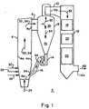
- the drawing is a schematic representation in the nature of a side elevational view of a circulating fluidized bed steam generator (CFB) including a furnace volume, a cyclone section cooperatively associated with the furnace volume, and a backpass volume cooperatively associated with the cyclone section, along with interconnecting ductwork and pipework, constructed in accordance with the present invention.
- CFB circulating fluidized bed steam generator
- the circulating fluidized bed steam generator 2 includes a furnace volume, denoted therein by the reference numeral 4, the latter being defined by waterwall tubes, denoted therein by the reference numeral 4a; a first section of ductwork, denoted therein by the reference numeral 6; a cyclone section, denoted therein by the reference numeral 8; a second section of ductwork, denoted therein by the reference numeral 10; a backpass volume, denoted therein by the reference numeral 12, from which ductwork, denoted therein by the reference numeral 12a, extends.
- a furnace volume denoted therein by the reference numeral 4
- the latter being defined by waterwall tubes, denoted therein by the reference numeral 4a
- a first section of ductwork denoted therein by the reference numeral 6
- a cyclone section denoted therein by the reference numeral 8
- a second section of ductwork denoted therein by the reference numeral 10
- the upper segment, denoted therein by the reference numeral 8b, of the cyclone 8 is connected in fluid flow relation with the upper segment of the furnace volume 4 by means of the first section of ductwork 6.
- the lower segment, denoted by the reference numeral 8c, of the cyclone 8 is connected in fluid flow relation with the lower segment of the furnace volume 4 by means of pipework, which in accordance with the illustration thereof in the drawing consists of a seal pot, denoted therein by the reference numeral 14 and a hot solids inlet, denoted therein by the reference numeral 16.
- the flow path which extends from the furnace volume 4 through the first section of ductwork 6 and through the cyclone 8 and the pipework 14,16, and returning to the lower segment of the furnace volume 4, will be referred to hereinafter as the hot solids circulation path 4, 6, 8, 14, 16, 4.
- the flow path which begins at the furnace exit, denoted in the drawing by the reference numeral 4c, and which continues through the first section of ductwork 6 and through the upper segment 8b of the cyclone 8, and which terminates at the cyclone exit, denoted in the drawing by the reference numeral 8a, will be referred to hereinafter as the afterburning volume 4c, 6, 8b, 8a.
- the furnace volume 4 is supplied with a mixture of fuel and sorbent, denoted in the drawing by the reference numeral 28, and a first source of air, denoted in the drawing by the reference numeral 24.
- the furnace volume 4 is also supplied with a second source of air, denoted in the drawing by the reference numeral 26, and a third source of air, denoted in the drawing by the reference numeral 30.
- the first source of air is fed through an air distributor, denoted in the drawing by the reference numeral 4c, to the lower segment of the furnace from therebeneath.
- the second source of air 26 and the third source of air 30, in accordance with the illustration thereof in the drawing, are suitably arranged relative to each other such that the third source of air 30 is located above the second source of air 26 and such that the mixture of fuel and sorbent 28 is interposed between the second source of air 26 and the third source of air 30.
- the hot combustion gases 32 with the hot solids 34 entrained therewith are made to flow through the first section of ductwork 6 to the cyclone 8.
- the hot solids 34 that are made to flow thereto which are above a predetermined size, are separated from the hot combustion gases 32 in which the hot solids 34 are entrained.
- the separated hot solids 34 which contain unburned fuel, flyash and sorbent flow through the cyclone. From the cyclone 8 the hot solids 34 are discharged under the influence of gravity into the seal pot 14.
- the hot solids 34 are reintroduced into the lower segment of the furnace volume 4 by means of the hot solids inlet 16 whereupon the hot solids 34 are once again subjected to the combustion process that takes place in the circulating fluidized bed steam generator 2.
- the hot combustion gases 32 leaving the cyclone 8, hereinafter referred to as flue gases are directed by means of the second section of ductwork 10 from the cyclone 8 to the backpass volume 12 of the circulating fluidized bed steam generator 2.
- flue gases 32 traverse the backpass volume 12 additional heat transfer duty is performed therewith in accordance with a predetermined thermodynamic steam cycle relative to the heat transfer surfaces, e.g., the superheater, the reheater and the economizer, denoted by the reference numerals 18, 20, 22, respectively, which are suitably located for this purpose in the backpass volume 12.
- the flue gases 32 exit through the ductwork 12a to a particulate removal system (not shown in the interest of maintaining clarity of illustration in the drawing) whereupon the flue gases 32 are discharged to the atmosphere through a stack (not shown in the interest of maintaining clarity of illustration in the drawing).
- the total amount of air supplied to the furnace volume 4 by the second source of air 26 and the third source of air 30 is ordinarily evenly distributed therebetween such that the furnace volume 4 is subjected to certain prescribed stoichiometric conditions.
- such prescribed stoichiometric conditions are designed to produce an essentially constant temperature of between approximately 1550 degrees F. and 1600 degrees F. throughout the furnace volume 4. It is also the desired intent that this temperature be essentially constant throughout the hot solids circulation path 4, 6, 8, 14, 16, 4, to which reference previously has been had herein.
- afterburning may occur to a very slight extent between the furnace exit 4c and the cyclone exit 8a.
- the term afterburning as employed herein is meant to refer to the combustion of unburned fuel, which occurs within the afterburning volume 4c, 6, 8b, 8a, to which reference previously has been had herein.
- the temperature of the flue gases 32 at the cyclone exit 8a will as a consequence of such afterburning slightly exceed the temperature of the hot combustion gases 32 at the furnace exit 4c.
- the distribution of the air 26, 30 is such that the amount of the third source of air 30, which is injected into the furnace volume 4, is greater than the amount of the second source of air 26, which is injected into the furnace volume 4, completion of the combustion of the fuel 28 will be delayed as the fuel 28 traverses the furnace volume 4.
- the lower segment of the furnace volume 4 will be operated under substoichiometric conditions and the upper segment of the furnace volume 4 will be operated under oxidizing conditions.
- this will result in a lowering of the overall furnace temperature as well as a lowering of the temperature gradient within the furnace volume 4 such that the temperature within the upper segment of the furnace volume 4 is greater than within the lower segment of the furnace volume 4.
- N 2 O emissions for a given fuel 28 and a given distribution of the air 26, 30 through controlled afterburning that is effected by manipulating the particle size of the fuel, which is intended to be subjected to combustion within the circulating fluidized bed steam generator 2.
- the effect thereof is that the lighter weight particles of fuel, i.e., the fuel particles of smaller size, will become more quickly entrained within the hot combustion gases 32, and thus will reach the upper segment of the furnace volume 4 before combustion thereof takes place. Consequently, completion of the combustion of the fuel 28 is delayed as the fuel 28 traverses the furnace volume 4. Therefore, combustion of the fuel 28 is not completed within the furnace volume 4.
- N 2 O emissions may in addition be reduced in accordance with the present invention by manipulating together in combination both the distribution of the air 26, 30 and the particle size of the fuel.
- the area of the superheat, reheat and economizer surfaces 18, 20, 22, respectively, that is necessary to effect therewith the required amount of heat transfer duty can be reduced. Consequently, in accordance with the present invention, in addition to the superheat, reheat and economizer surfaces 18, 20, 22, respectively, being reduced the backpass volume 12 may also be reduced with attendant cost savings being realizable from the reduction in the superheat, reheat and economizer surfaces 18, 20, 22, respectively, and/or from the reduction in the backpass volume 12.
- a new and improved method for reducing N 2 O emissions there has been provided a new and improved method for reducing N 2 O emissions. Besides, there has been provided in accord with the present invention such a new and improved method for reducing N 2 O emissions, which is particularly suited for effecting therewith the reduction of N 2 O emissions from a circulating fluidized bed steam generator (CFB). Moreover, in accordance with the present invention there has been provided such a new and improved method for reducing N 2 O emissions from a circulating fluidized bed steam generator (CFB), which is characterized in that such reduction of N 2 O emissions is achievable therewith without at the same time increasing either the level of NO x emissions or the level of SO x emissions from the circulating fluidized bed steam generator (CFB).
Abstract
Description
Claims (12)
- In a circulating fluidized bed steam generator including a furnace volume having an exit therefrom provided at at least one end thereof, a cyclone operative as both a separator and a combustor and having an exit therefrom provided at at least one end thereof, a backpass volume embodying therewithin heat transfer surfaces, first conduit means connecting the furnace volume in fluid flow relation with the cyclone, and second conduit means connecting the cyclone in fluid flow relation with the backpass volume, the improvement of a method for controlling N2O emissions from the circulating fluidized bed steam generator, said method for controlling N2O emissions from the circulating fluidized bed steam generator comprising the steps of :a. injecting fuel of a predetermined size into the furnace volume;b. injecting from beneath the furnace volume air from a first source thereof into the furnace volume;c. injecting air from a second source thereof into the furnace volume below the point of injection of the fuel into the furnace volume;d. injecting air from a third source thereof into the furnace volume above the point of injection of the fuel into the furnace volume;e. effecting partial combustion of the fuel within the furnace volume causing flue gases and hot solids to be generated as a consequence of such partial combustion of the fuel;f. delaying the remainder of the combustion of the fuel until the fuel has passed beyond the exit of the furnace volume; andg. effecting completion of the remainder of the combustion of the fuel between the exit of the furnace volume and the exit of the cyclone so as to produce a temperature therefrom operative to effect a reduction in N2O emissions.
- In a circulating fluidized bed steam generator, the method of controlling N2O emissions from a circulating fluidized bed steam generator as set forth in Claim 1 wherein the partial combustion of the fuel within the furnace volume is effected so as to produce a temperature therefrom low enough to maintain NOx emissions and SOx emissions from the circulating fluidized bed steam generator at acceptable levels.
- In a circulating fluidized bed steam generator, the method of controlling N2O emissions from a circulating fluidized bed steam generator as set forth in Claim 2 wherein the delay in effecting the combustion of the remainder of the fuel is occasioned by the manipulation of the distribution of air injected into the furnace volume from the second source of air and from the third source of air.
- In a circulating fluidized bed steam generator, the method of controlling N2O emissions from a circulating fluidized bed steam generator as set forth in Claim 3 wherein the amount of air injected into the furnace volume from the third source of air is greater than the amount of air injected into the furnace volume from the second source of air.
- In a circulating fluidized bed steam generator, the method of controlling N2O emissions from a circulating fluidized bed steam generator as set forth in Claim 2 wherein the delay in effecting the combustion of the remainder of the fuel is occasioned by the manipulation of the particle size of the fuel.
- In a circulating fluidized bed steam generator, the method of controlling N2O emissions from a circulating fluidized bed steam generator as set forth in Claim 2 wherein the delay in effecting the combustion of the remainder of the fuel is occasioned both by the manipulation of the distribution of air injected into the furnace volume from the second source of air and from the third source of air and by the manipulation of the particle size of the fuel.
- In a circulating fluidized bed steam generator, the method of controlling N2O emissions from a circulating fluidized bed steam generator as set forth in Claim 2 wherein the air injected into the furnace volume from a first source of air is injected into the furnace volume through an air distribution means.
- In a circulating fluidized bed steam generator, the method of controlling N2O emissions from a circulating fluidized bed steam generator as set forth in Claim 2 further comprising the step of maintaining the desired overall efficiency of the circulating fluidized bed steam generator.
- In a circulating fluidized bed steam generator, the method of controlling N2O emissions from a circulating fluidized bed steam generator as set forth in Claim 2 further comprising the step of maintaining the desired stoichiometric ratio of the combustion process occurring within the circulating fluidized bed steam generator.
- In a circulating fluidized bed steam generator, the method of controlling N2O emissions from a circulating fluidized bed steam generator as set forth in Claim 2 wherein the cyclone is operative to effect therewithin the separation from the flue gases of the hot solids entrained therewith.
- In a circulating fluidized bed steam generator, the method of controlling N2O emissions from a circulating fluidized bed steam generator as set forth in Claim 2 wherein the cyclone is operative to effect the combustion of the remainder of the fuel therewithin.
- In a circulating fluidized bed steam generator, the method of controlling N2O emissions from a circulating fluidized bed steam generator as set forth in Claim 2 wherein the cyclone is operative both to effect therewithin the separation from the flue gases of the hot solids entrained therewith and to effect the combustion of the remainder of the fuel therewithin.
Applications Claiming Priority (2)
| Application Number | Priority Date | Filing Date | Title |
|---|---|---|---|
| US77476396A | 1996-12-30 | 1996-12-30 | |
| US774763 | 1996-12-30 |
Publications (3)
| Publication Number | Publication Date |
|---|---|
| EP0851173A2 true EP0851173A2 (en) | 1998-07-01 |
| EP0851173A3 EP0851173A3 (en) | 1999-07-28 |
| EP0851173B1 EP0851173B1 (en) | 2002-11-20 |
Family
ID=25102207
Family Applications (1)
| Application Number | Title | Priority Date | Filing Date |
|---|---|---|---|
| EP97122925A Expired - Lifetime EP0851173B1 (en) | 1996-12-30 | 1997-12-29 | A method of controlling nitrous oxide in circulating fluidized bed steam generators |
Country Status (3)
| Country | Link |
|---|---|
| EP (1) | EP0851173B1 (en) |
| AT (1) | ATE228225T1 (en) |
| DE (1) | DE69717240D1 (en) |
Cited By (8)
| Publication number | Priority date | Publication date | Assignee | Title |
|---|---|---|---|---|
| EP1846694A1 (en) * | 2005-02-11 | 2007-10-24 | Metso Power Oy | A method for reducing nitrogen oxide emissions of a bubbling fluidized bed boiler and an air distribution system of a bubbling fluidized bed boiler |
| JP2010175157A (en) * | 2009-01-30 | 2010-08-12 | Metawater Co Ltd | Fluidized incinerator |
| CN102278743A (en) * | 2011-08-16 | 2011-12-14 | 江苏太湖锅炉股份有限公司 | Recirculating fluidized bed boiler |
| CN102721046A (en) * | 2012-07-06 | 2012-10-10 | 无锡华光锅炉股份有限公司 | Circulating fluidized bed boiler for combustion papermaking waste residue and sludge |
| JP2013050292A (en) * | 2011-08-04 | 2013-03-14 | Mitsubishi Heavy Ind Ltd | Fluidized-bed processing system and method of removing n2o in fluidized-bed combustion exhaust gas |
| CN104748108A (en) * | 2015-04-10 | 2015-07-01 | 东方电气集团东方锅炉股份有限公司 | Cooperative-control CFB (Circulating Fluidized Bed) boiler in-furnace desulphurization and denitration burning system and cooperative-control CFB boiler in-furnace desulphurization and denitration burning method |
| CN105465771A (en) * | 2015-11-06 | 2016-04-06 | 广东工业大学 | Cyclone type coarse pulverized coal gasified combustion device |
| CN112413573A (en) * | 2019-08-21 | 2021-02-26 | 中国科学院工程热物理研究所 | Oxygen-enriched combustion system and oxygen-enriched combustion method of circulating fluidized bed |
Citations (7)
| Publication number | Priority date | Publication date | Assignee | Title |
|---|---|---|---|---|
| EP0406185A2 (en) | 1989-06-01 | 1991-01-02 | Kvaerner Enviropower Ab | Fluid bed furnace |
| DE3933286A1 (en) | 1989-10-05 | 1991-04-18 | Steinmueller Gmbh L & C | METHOD FOR REDUCING THE NUMBER OF NITROGEN OXIDES IN THE SMOKE GASES OF A BURNER |
| US5048432A (en) | 1990-12-27 | 1991-09-17 | Nalco Fuel Tech | Process and apparatus for the thermal decomposition of nitrous oxide |
| US5171553A (en) | 1991-11-08 | 1992-12-15 | Air Products And Chemicals, Inc. | Catalytic decomposition of N2 O |
| US5325796A (en) | 1992-05-22 | 1994-07-05 | Foster Wheeler Energy Corporation | Process for decreasing N2 O emissions from a fluidized bed reactor |
| US5344629A (en) | 1992-01-03 | 1994-09-06 | A. Ahlstrom Corporation | Reducing Z20 emissions |
| US5378443A (en) | 1992-01-03 | 1995-01-03 | A. Ahlstrom Corporation | Method for reducing emissions when burning nitrogen containing fuels |
Family Cites Families (5)
| Publication number | Priority date | Publication date | Assignee | Title |
|---|---|---|---|---|
| FR2587090B1 (en) * | 1985-09-09 | 1987-12-04 | Framatome Sa | CIRCULATING FLUIDIZED BED BOILER |
| WO1993018341A1 (en) * | 1992-03-05 | 1993-09-16 | Technische Universiteit Delft | Method and apparatus for combusting a carbonaceous material |
| JP2889049B2 (en) * | 1992-06-09 | 1999-05-10 | 株式会社神戸製鋼所 | Method for reducing N2O and NOx in fluidized bed combustion |
| SE502292C2 (en) * | 1994-08-19 | 1995-10-02 | Kvaerner Enviropower Ab | Method for two-stage combustion of solid fuels in a circulating fluidized bed |
| US5660125A (en) * | 1995-05-05 | 1997-08-26 | Combustion Engineering, Inc. | Circulating fluid bed steam generator NOx control |
-
1997
- 1997-12-29 DE DE69717240T patent/DE69717240D1/en not_active Expired - Lifetime
- 1997-12-29 EP EP97122925A patent/EP0851173B1/en not_active Expired - Lifetime
- 1997-12-29 AT AT97122925T patent/ATE228225T1/en not_active IP Right Cessation
Patent Citations (8)
| Publication number | Priority date | Publication date | Assignee | Title |
|---|---|---|---|---|
| EP0406185A2 (en) | 1989-06-01 | 1991-01-02 | Kvaerner Enviropower Ab | Fluid bed furnace |
| DE3933286A1 (en) | 1989-10-05 | 1991-04-18 | Steinmueller Gmbh L & C | METHOD FOR REDUCING THE NUMBER OF NITROGEN OXIDES IN THE SMOKE GASES OF A BURNER |
| US5048432A (en) | 1990-12-27 | 1991-09-17 | Nalco Fuel Tech | Process and apparatus for the thermal decomposition of nitrous oxide |
| US5048432B1 (en) | 1990-12-27 | 1996-07-02 | Nalco Fuel Tech | Process and apparatus for the thermal decomposition of nitrous oxide |
| US5171553A (en) | 1991-11-08 | 1992-12-15 | Air Products And Chemicals, Inc. | Catalytic decomposition of N2 O |
| US5344629A (en) | 1992-01-03 | 1994-09-06 | A. Ahlstrom Corporation | Reducing Z20 emissions |
| US5378443A (en) | 1992-01-03 | 1995-01-03 | A. Ahlstrom Corporation | Method for reducing emissions when burning nitrogen containing fuels |
| US5325796A (en) | 1992-05-22 | 1994-07-05 | Foster Wheeler Energy Corporation | Process for decreasing N2 O emissions from a fluidized bed reactor |
Non-Patent Citations (1)
| Title |
|---|
| L.E. AMAND & B. LEAKNER: "formation of N2O in a circulating fluidized-bed combustor", ENERGY & FUELS, vol. 7, 1993 |
Cited By (13)
| Publication number | Priority date | Publication date | Assignee | Title |
|---|---|---|---|---|
| EP1846694A4 (en) * | 2005-02-11 | 2012-01-04 | Metso Power Oy | A method for reducing nitrogen oxide emissions of a bubbling fluidized bed boiler and an air distribution system of a bubbling fluidized bed boiler |
| EP1846694A1 (en) * | 2005-02-11 | 2007-10-24 | Metso Power Oy | A method for reducing nitrogen oxide emissions of a bubbling fluidized bed boiler and an air distribution system of a bubbling fluidized bed boiler |
| JP2010175157A (en) * | 2009-01-30 | 2010-08-12 | Metawater Co Ltd | Fluidized incinerator |
| JP2013050292A (en) * | 2011-08-04 | 2013-03-14 | Mitsubishi Heavy Ind Ltd | Fluidized-bed processing system and method of removing n2o in fluidized-bed combustion exhaust gas |
| CN102278743A (en) * | 2011-08-16 | 2011-12-14 | 江苏太湖锅炉股份有限公司 | Recirculating fluidized bed boiler |
| CN102721046B (en) * | 2012-07-06 | 2015-01-14 | 无锡华光锅炉股份有限公司 | Circulating fluidized bed boiler for combustion papermaking waste residue and sludge |
| CN102721046A (en) * | 2012-07-06 | 2012-10-10 | 无锡华光锅炉股份有限公司 | Circulating fluidized bed boiler for combustion papermaking waste residue and sludge |
| CN104748108A (en) * | 2015-04-10 | 2015-07-01 | 东方电气集团东方锅炉股份有限公司 | Cooperative-control CFB (Circulating Fluidized Bed) boiler in-furnace desulphurization and denitration burning system and cooperative-control CFB boiler in-furnace desulphurization and denitration burning method |
| CN104748108B (en) * | 2015-04-10 | 2017-05-31 | 东方电气集团东方锅炉股份有限公司 | The combustion system and method for Collaborative Control CFB boiler in-furnace desulfurization, denitration |
| CN105465771A (en) * | 2015-11-06 | 2016-04-06 | 广东工业大学 | Cyclone type coarse pulverized coal gasified combustion device |
| WO2017075969A1 (en) * | 2015-11-06 | 2017-05-11 | 广东工业大学 | Cyclone coarse coal powder gasification combustion device |
| CN112413573A (en) * | 2019-08-21 | 2021-02-26 | 中国科学院工程热物理研究所 | Oxygen-enriched combustion system and oxygen-enriched combustion method of circulating fluidized bed |
| CN112413573B (en) * | 2019-08-21 | 2022-12-27 | 中国科学院工程热物理研究所 | Oxygen-enriched combustion system and oxygen-enriched combustion method of circulating fluidized bed |
Also Published As
| Publication number | Publication date |
|---|---|
| DE69717240D1 (en) | 2003-01-02 |
| EP0851173A3 (en) | 1999-07-28 |
| EP0851173B1 (en) | 2002-11-20 |
| ATE228225T1 (en) | 2002-12-15 |
Similar Documents
| Publication | Publication Date | Title |
|---|---|---|
| CA2086575C (en) | Method for reducing emissions when burning nitrogen containing fuels | |
| CA2712870C (en) | Air-fired co2 capture ready circulating fluidized bed heat generation with a reactor subsystem | |
| de Diego et al. | Influence of operating parameters on NOx and N2O axial profiles in a circulating fluidized bed combustor | |
| US4843981A (en) | Fines recirculating fluid bed combustor method and apparatus | |
| CZ287910B6 (en) | Purification process of combustion products containing nitrogen oxides from a fuel reaction zone of a steam producer and a steam producer for making the same | |
| CN104437082A (en) | Ultra-clean discharge system and method for fluidized bed boiler | |
| KR100829346B1 (en) | Circulating fluidized bed reactor with selective catalytic reduction | |
| CA1166010A (en) | Integral vapor generator/gasifier system | |
| CN105838401A (en) | Method and system for processing pollutant resulting from coal fines pyrolysis and boiler combustion system | |
| JPH10504637A (en) | Combustion method | |
| EP0698763B1 (en) | Circulating fluidized bed repowering to reduce SOx and NOx emissions from industrial and utility boilers | |
| EP0851173B1 (en) | A method of controlling nitrous oxide in circulating fluidized bed steam generators | |
| US11850550B2 (en) | Arrangement for and a method of operating a steam boiler system | |
| AU702441B2 (en) | Circulating fluid bed steam generator nox control | |
| CN112082151B (en) | Multi-pollutant collaborative removing and burning device and method for circulating fluidized bed boiler | |
| US4782771A (en) | Method of reducing the content of nitrogen oxides in multiple bed composition boilers | |
| US5396849A (en) | Combustion method producing low levels of pollutants and apparatus for same | |
| JPH05149508A (en) | Fluidized-bed combustion method utilizing supply fine and coarse adsorbent | |
| CA2095486A1 (en) | Process for decreasing n2o emmissions from a fluidized bed reactor | |
| JP3067890B2 (en) | Method and apparatus for treating exhaust gas from catalytic cracking equipment | |
| JPH05180413A (en) | Fluidized bed combustion boilers | |
| Wang et al. | Influence of limestone addition on combustion and emission characteristics of coal slime in the 75 t/h CFB boiler with post-combustion chamber | |
| JP2000213707A (en) | Combustion apparatus | |
| CN104511234B (en) | A kind of clean exhaust system for fluidized-bed combustion boiler and method | |
| JPH0823401B2 (en) | Fluidized bed reactor with flue gas bypass device and method of operating the device |
Legal Events
| Date | Code | Title | Description |
|---|---|---|---|
| PUAI | Public reference made under article 153(3) epc to a published international application that has entered the european phase |
Free format text: ORIGINAL CODE: 0009012 |
|
| AK | Designated contracting states |
Kind code of ref document: A2 Designated state(s): AT BE DE DK ES FI FR GB IE IT NL PT SE |
|
| AX | Request for extension of the european patent |
Free format text: AL;LT;LV;MK;RO PAYMENT 971229;SI PAYMENT 971229 |
|
| PUAL | Search report despatched |
Free format text: ORIGINAL CODE: 0009013 |
|
| AK | Designated contracting states |
Kind code of ref document: A3 Designated state(s): AT BE CH DE DK ES FI FR GB GR IE IT LI LU MC NL PT SE |
|
| AX | Request for extension of the european patent |
Free format text: AL;LT;LV;MK;RO PAYMENT 19971229;SI PAYMENT 19971229 |
|
| 17P | Request for examination filed |
Effective date: 19990914 |
|
| AKX | Designation fees paid |
Free format text: AT BE DE DK ES FI FR GB IE IT NL PT SE |
|
| AXX | Extension fees paid |
Free format text: RO PAYMENT 19971229;SI PAYMENT 19971229 |
|
| RAP1 | Party data changed (applicant data changed or rights of an application transferred) |
Owner name: ABB ALSTOM POWER INC. |
|
| 17Q | First examination report despatched |
Effective date: 20010111 |
|
| RAP1 | Party data changed (applicant data changed or rights of an application transferred) |
Owner name: ALSTOM POWER INC. |
|
| GRAG | Despatch of communication of intention to grant |
Free format text: ORIGINAL CODE: EPIDOS AGRA |
|
| GRAG | Despatch of communication of intention to grant |
Free format text: ORIGINAL CODE: EPIDOS AGRA |
|
| GRAH | Despatch of communication of intention to grant a patent |
Free format text: ORIGINAL CODE: EPIDOS IGRA |
|
| GRAH | Despatch of communication of intention to grant a patent |
Free format text: ORIGINAL CODE: EPIDOS IGRA |
|
| GRAA | (expected) grant |
Free format text: ORIGINAL CODE: 0009210 |
|
| AK | Designated contracting states |
Kind code of ref document: B1 Designated state(s): AT BE DE DK ES FI FR GB IE IT NL PT SE |
|
| AX | Request for extension of the european patent |
Free format text: RO PAYMENT 19971229;SI PAYMENT 19971229 |
|
| PG25 | Lapsed in a contracting state [announced via postgrant information from national office to epo] |
Ref country code: NL Free format text: LAPSE BECAUSE OF FAILURE TO SUBMIT A TRANSLATION OF THE DESCRIPTION OR TO PAY THE FEE WITHIN THE PRESCRIBED TIME-LIMIT Effective date: 20021120 Ref country code: IT Free format text: LAPSE BECAUSE OF FAILURE TO SUBMIT A TRANSLATION OF THE DESCRIPTION OR TO PAY THE FEE WITHIN THE PRE;WARNING: LAPSES OF ITALIAN PATENTS WITH EFFECTIVE DATE BEFORE 2007 MAY HAVE OCCURRED AT ANY TIME BEFORE 2007. THE CORRECT EFFECTIVE DATE MAY BE DIFFERENT FROM THE ONE RECORDED.SCRIBED TIME-LIMIT Effective date: 20021120 Ref country code: FR Free format text: LAPSE BECAUSE OF FAILURE TO SUBMIT A TRANSLATION OF THE DESCRIPTION OR TO PAY THE FEE WITHIN THE PRESCRIBED TIME-LIMIT Effective date: 20021120 Ref country code: FI Free format text: LAPSE BECAUSE OF FAILURE TO SUBMIT A TRANSLATION OF THE DESCRIPTION OR TO PAY THE FEE WITHIN THE PRESCRIBED TIME-LIMIT Effective date: 20021120 Ref country code: BE Free format text: LAPSE BECAUSE OF FAILURE TO SUBMIT A TRANSLATION OF THE DESCRIPTION OR TO PAY THE FEE WITHIN THE PRESCRIBED TIME-LIMIT Effective date: 20021120 Ref country code: AT Free format text: LAPSE BECAUSE OF FAILURE TO SUBMIT A TRANSLATION OF THE DESCRIPTION OR TO PAY THE FEE WITHIN THE PRESCRIBED TIME-LIMIT Effective date: 20021120 |
|
| REF | Corresponds to: |
Ref document number: 228225 Country of ref document: AT Date of ref document: 20021215 Kind code of ref document: T |
|
| REG | Reference to a national code |
Ref country code: GB Ref legal event code: FG4D |
|
| RIC1 | Information provided on ipc code assigned before grant |
Free format text: 7F 23C 10/10 A, 7F 23C 6/04 B |
|
| PG25 | Lapsed in a contracting state [announced via postgrant information from national office to epo] |
Ref country code: IE Free format text: LAPSE BECAUSE OF NON-PAYMENT OF DUE FEES Effective date: 20021230 |
|
| REG | Reference to a national code |
Ref country code: IE Ref legal event code: FG4D |
|
| REF | Corresponds to: |
Ref document number: 69717240 Country of ref document: DE Date of ref document: 20030102 |
|
| PG25 | Lapsed in a contracting state [announced via postgrant information from national office to epo] |
Ref country code: SE Free format text: LAPSE BECAUSE OF FAILURE TO SUBMIT A TRANSLATION OF THE DESCRIPTION OR TO PAY THE FEE WITHIN THE PRESCRIBED TIME-LIMIT Effective date: 20030220 Ref country code: PT Free format text: LAPSE BECAUSE OF FAILURE TO SUBMIT A TRANSLATION OF THE DESCRIPTION OR TO PAY THE FEE WITHIN THE PRESCRIBED TIME-LIMIT Effective date: 20030220 Ref country code: GB Free format text: LAPSE BECAUSE OF NON-PAYMENT OF DUE FEES Effective date: 20030220 Ref country code: DK Free format text: LAPSE BECAUSE OF FAILURE TO SUBMIT A TRANSLATION OF THE DESCRIPTION OR TO PAY THE FEE WITHIN THE PRESCRIBED TIME-LIMIT Effective date: 20030220 |
|
| PG25 | Lapsed in a contracting state [announced via postgrant information from national office to epo] |
Ref country code: DE Free format text: LAPSE BECAUSE OF FAILURE TO SUBMIT A TRANSLATION OF THE DESCRIPTION OR TO PAY THE FEE WITHIN THE PRESCRIBED TIME-LIMIT Effective date: 20030221 |
|
| NLV1 | Nl: lapsed or annulled due to failure to fulfill the requirements of art. 29p and 29m of the patents act | ||
| PG25 | Lapsed in a contracting state [announced via postgrant information from national office to epo] |
Ref country code: ES Free format text: LAPSE BECAUSE OF FAILURE TO SUBMIT A TRANSLATION OF THE DESCRIPTION OR TO PAY THE FEE WITHIN THE PRESCRIBED TIME-LIMIT Effective date: 20030529 |
|
| EN | Fr: translation not filed | ||
| PLBE | No opposition filed within time limit |
Free format text: ORIGINAL CODE: 0009261 |
|
| STAA | Information on the status of an ep patent application or granted ep patent |
Free format text: STATUS: NO OPPOSITION FILED WITHIN TIME LIMIT |
|
| REG | Reference to a national code |
Ref country code: IE Ref legal event code: MM4A |
|
| GBPC | Gb: european patent ceased through non-payment of renewal fee | ||
| 26N | No opposition filed |
Effective date: 20030821 |