EP0432293B1 - Method for recovering waste gases from coal combustor - Google Patents
Method for recovering waste gases from coal combustor Download PDFInfo
- Publication number
- EP0432293B1 EP0432293B1 EP89122954A EP89122954A EP0432293B1 EP 0432293 B1 EP0432293 B1 EP 0432293B1 EP 89122954 A EP89122954 A EP 89122954A EP 89122954 A EP89122954 A EP 89122954A EP 0432293 B1 EP0432293 B1 EP 0432293B1
- Authority
- EP
- European Patent Office
- Prior art keywords
- gases
- heat
- exhaust gases
- fuel
- air
- Prior art date
- Legal status (The legal status is an assumption and is not a legal conclusion. Google has not performed a legal analysis and makes no representation as to the accuracy of the status listed.)
- Expired - Lifetime
Links
- 239000003245 coal Substances 0.000 title claims description 40
- 238000000034 method Methods 0.000 title claims description 20
- 239000002912 waste gas Substances 0.000 title description 11
- 239000007789 gas Substances 0.000 claims description 88
- 238000002485 combustion reaction Methods 0.000 claims description 52
- 239000000446 fuel Substances 0.000 claims description 42
- 238000011084 recovery Methods 0.000 claims description 30
- 239000000203 mixture Substances 0.000 claims description 24
- 238000006243 chemical reaction Methods 0.000 claims description 18
- 238000002347 injection Methods 0.000 claims description 17
- 239000007924 injection Substances 0.000 claims description 17
- 238000006477 desulfuration reaction Methods 0.000 claims description 11
- 230000023556 desulfurization Effects 0.000 claims description 11
- 239000002893 slag Substances 0.000 claims description 10
- 239000007800 oxidant agent Substances 0.000 claims description 8
- 239000000571 coke Substances 0.000 claims description 7
- QVGXLLKOCUKJST-UHFFFAOYSA-N atomic oxygen Chemical compound [O] QVGXLLKOCUKJST-UHFFFAOYSA-N 0.000 claims description 6
- 239000001301 oxygen Substances 0.000 claims description 6
- 229910052760 oxygen Inorganic materials 0.000 claims description 6
- 238000010791 quenching Methods 0.000 claims description 5
- 230000000171 quenching effect Effects 0.000 claims description 5
- 239000000126 substance Substances 0.000 claims description 3
- 238000002156 mixing Methods 0.000 claims 1
- 239000003570 air Substances 0.000 description 43
- 239000002956 ash Substances 0.000 description 13
- MYMOFIZGZYHOMD-UHFFFAOYSA-N Dioxygen Chemical compound O=O MYMOFIZGZYHOMD-UHFFFAOYSA-N 0.000 description 11
- 229910001882 dioxygen Inorganic materials 0.000 description 11
- 239000006227 byproduct Substances 0.000 description 7
- 239000000047 product Substances 0.000 description 6
- IJGRMHOSHXDMSA-UHFFFAOYSA-N Atomic nitrogen Chemical compound N#N IJGRMHOSHXDMSA-UHFFFAOYSA-N 0.000 description 4
- NINIDFKCEFEMDL-UHFFFAOYSA-N Sulfur Chemical compound [S] NINIDFKCEFEMDL-UHFFFAOYSA-N 0.000 description 4
- 238000001311 chemical methods and process Methods 0.000 description 4
- 229910001873 dinitrogen Inorganic materials 0.000 description 4
- 239000000428 dust Substances 0.000 description 4
- 239000010881 fly ash Substances 0.000 description 4
- 238000010438 heat treatment Methods 0.000 description 4
- 239000002245 particle Substances 0.000 description 4
- 239000003476 subbituminous coal Substances 0.000 description 4
- 229910052717 sulfur Inorganic materials 0.000 description 4
- 239000011593 sulfur Substances 0.000 description 4
- 150000003464 sulfur compounds Chemical class 0.000 description 4
- UGFAIRIUMAVXCW-UHFFFAOYSA-N Carbon monoxide Chemical compound [O+]#[C-] UGFAIRIUMAVXCW-UHFFFAOYSA-N 0.000 description 3
- 239000002802 bituminous coal Substances 0.000 description 3
- 229910002091 carbon monoxide Inorganic materials 0.000 description 3
- 238000001816 cooling Methods 0.000 description 3
- 239000012530 fluid Substances 0.000 description 3
- 238000002309 gasification Methods 0.000 description 3
- 239000001257 hydrogen Substances 0.000 description 3
- 229910052739 hydrogen Inorganic materials 0.000 description 3
- 125000004435 hydrogen atom Chemical class [H]* 0.000 description 3
- 239000003350 kerosene Substances 0.000 description 3
- 238000007796 conventional method Methods 0.000 description 2
- 230000004927 fusion Effects 0.000 description 2
- VNWKTOKETHGBQD-UHFFFAOYSA-N methane Chemical compound C VNWKTOKETHGBQD-UHFFFAOYSA-N 0.000 description 2
- 230000004048 modification Effects 0.000 description 2
- 238000012986 modification Methods 0.000 description 2
- XLYOFNOQVPJJNP-UHFFFAOYSA-N water Substances O XLYOFNOQVPJJNP-UHFFFAOYSA-N 0.000 description 2
- 239000003054 catalyst Substances 0.000 description 1
- 238000007084 catalytic combustion reaction Methods 0.000 description 1
- 239000000919 ceramic Substances 0.000 description 1
- 238000010586 diagram Methods 0.000 description 1
- 230000000694 effects Effects 0.000 description 1
- 230000008030 elimination Effects 0.000 description 1
- 238000003379 elimination reaction Methods 0.000 description 1
- 238000002474 experimental method Methods 0.000 description 1
- 239000002803 fossil fuel Substances 0.000 description 1
- 239000004615 ingredient Substances 0.000 description 1
- 239000007788 liquid Substances 0.000 description 1
- 238000004519 manufacturing process Methods 0.000 description 1
- 230000001590 oxidative effect Effects 0.000 description 1
- 238000010298 pulverizing process Methods 0.000 description 1
- 238000000746 purification Methods 0.000 description 1
- 230000003134 recirculating effect Effects 0.000 description 1
- 238000010079 rubber tapping Methods 0.000 description 1
- 238000011144 upstream manufacturing Methods 0.000 description 1
Images


Classifications
-
- F—MECHANICAL ENGINEERING; LIGHTING; HEATING; WEAPONS; BLASTING
- F23—COMBUSTION APPARATUS; COMBUSTION PROCESSES
- F23C—METHODS OR APPARATUS FOR COMBUSTION USING FLUID FUEL OR SOLID FUEL SUSPENDED IN A CARRIER GAS OR AIR
- F23C99/00—Subject-matter not provided for in other groups of this subclass
-
- C—CHEMISTRY; METALLURGY
- C10—PETROLEUM, GAS OR COKE INDUSTRIES; TECHNICAL GASES CONTAINING CARBON MONOXIDE; FUELS; LUBRICANTS; PEAT
- C10J—PRODUCTION OF PRODUCER GAS, WATER-GAS, SYNTHESIS GAS FROM SOLID CARBONACEOUS MATERIAL, OR MIXTURES CONTAINING THESE GASES; CARBURETTING AIR OR OTHER GASES
- C10J3/00—Production of combustible gases containing carbon monoxide from solid carbonaceous fuels
- C10J3/46—Gasification of granular or pulverulent flues in suspension
- C10J3/48—Apparatus; Plants
- C10J3/485—Entrained flow gasifiers
- C10J3/487—Swirling or cyclonic gasifiers
-
- C—CHEMISTRY; METALLURGY
- C10—PETROLEUM, GAS OR COKE INDUSTRIES; TECHNICAL GASES CONTAINING CARBON MONOXIDE; FUELS; LUBRICANTS; PEAT
- C10J—PRODUCTION OF PRODUCER GAS, WATER-GAS, SYNTHESIS GAS FROM SOLID CARBONACEOUS MATERIAL, OR MIXTURES CONTAINING THESE GASES; CARBURETTING AIR OR OTHER GASES
- C10J3/00—Production of combustible gases containing carbon monoxide from solid carbonaceous fuels
- C10J3/72—Other features
- C10J3/86—Other features combined with waste-heat boilers
-
- C—CHEMISTRY; METALLURGY
- C10—PETROLEUM, GAS OR COKE INDUSTRIES; TECHNICAL GASES CONTAINING CARBON MONOXIDE; FUELS; LUBRICANTS; PEAT
- C10K—PURIFYING OR MODIFYING THE CHEMICAL COMPOSITION OF COMBUSTIBLE GASES CONTAINING CARBON MONOXIDE
- C10K1/00—Purifying combustible gases containing carbon monoxide
- C10K1/002—Removal of contaminants
- C10K1/003—Removal of contaminants of acid contaminants, e.g. acid gas removal
- C10K1/004—Sulfur containing contaminants, e.g. hydrogen sulfide
-
- C—CHEMISTRY; METALLURGY
- C10—PETROLEUM, GAS OR COKE INDUSTRIES; TECHNICAL GASES CONTAINING CARBON MONOXIDE; FUELS; LUBRICANTS; PEAT
- C10K—PURIFYING OR MODIFYING THE CHEMICAL COMPOSITION OF COMBUSTIBLE GASES CONTAINING CARBON MONOXIDE
- C10K1/00—Purifying combustible gases containing carbon monoxide
- C10K1/02—Dust removal
- C10K1/024—Dust removal by filtration
-
- C—CHEMISTRY; METALLURGY
- C10—PETROLEUM, GAS OR COKE INDUSTRIES; TECHNICAL GASES CONTAINING CARBON MONOXIDE; FUELS; LUBRICANTS; PEAT
- C10K—PURIFYING OR MODIFYING THE CHEMICAL COMPOSITION OF COMBUSTIBLE GASES CONTAINING CARBON MONOXIDE
- C10K1/00—Purifying combustible gases containing carbon monoxide
- C10K1/02—Dust removal
- C10K1/026—Dust removal by centrifugal forces
-
- F—MECHANICAL ENGINEERING; LIGHTING; HEATING; WEAPONS; BLASTING
- F23—COMBUSTION APPARATUS; COMBUSTION PROCESSES
- F23C—METHODS OR APPARATUS FOR COMBUSTION USING FLUID FUEL OR SOLID FUEL SUSPENDED IN A CARRIER GAS OR AIR
- F23C3/00—Combustion apparatus characterised by the shape of the combustion chamber
- F23C3/006—Combustion apparatus characterised by the shape of the combustion chamber the chamber being arranged for cyclonic combustion
- F23C3/008—Combustion apparatus characterised by the shape of the combustion chamber the chamber being arranged for cyclonic combustion for pulverulent fuel
-
- C—CHEMISTRY; METALLURGY
- C10—PETROLEUM, GAS OR COKE INDUSTRIES; TECHNICAL GASES CONTAINING CARBON MONOXIDE; FUELS; LUBRICANTS; PEAT
- C10J—PRODUCTION OF PRODUCER GAS, WATER-GAS, SYNTHESIS GAS FROM SOLID CARBONACEOUS MATERIAL, OR MIXTURES CONTAINING THESE GASES; CARBURETTING AIR OR OTHER GASES
- C10J2300/00—Details of gasification processes
- C10J2300/09—Details of the feed, e.g. feeding of spent catalyst, inert gas or halogens
- C10J2300/0903—Feed preparation
- C10J2300/0906—Physical processes, e.g. shredding, comminuting, chopping, sorting
-
- C—CHEMISTRY; METALLURGY
- C10—PETROLEUM, GAS OR COKE INDUSTRIES; TECHNICAL GASES CONTAINING CARBON MONOXIDE; FUELS; LUBRICANTS; PEAT
- C10J—PRODUCTION OF PRODUCER GAS, WATER-GAS, SYNTHESIS GAS FROM SOLID CARBONACEOUS MATERIAL, OR MIXTURES CONTAINING THESE GASES; CARBURETTING AIR OR OTHER GASES
- C10J2300/00—Details of gasification processes
- C10J2300/09—Details of the feed, e.g. feeding of spent catalyst, inert gas or halogens
- C10J2300/0913—Carbonaceous raw material
- C10J2300/093—Coal
-
- C—CHEMISTRY; METALLURGY
- C10—PETROLEUM, GAS OR COKE INDUSTRIES; TECHNICAL GASES CONTAINING CARBON MONOXIDE; FUELS; LUBRICANTS; PEAT
- C10J—PRODUCTION OF PRODUCER GAS, WATER-GAS, SYNTHESIS GAS FROM SOLID CARBONACEOUS MATERIAL, OR MIXTURES CONTAINING THESE GASES; CARBURETTING AIR OR OTHER GASES
- C10J2300/00—Details of gasification processes
- C10J2300/09—Details of the feed, e.g. feeding of spent catalyst, inert gas or halogens
- C10J2300/0953—Gasifying agents
- C10J2300/0956—Air or oxygen enriched air
-
- C—CHEMISTRY; METALLURGY
- C10—PETROLEUM, GAS OR COKE INDUSTRIES; TECHNICAL GASES CONTAINING CARBON MONOXIDE; FUELS; LUBRICANTS; PEAT
- C10J—PRODUCTION OF PRODUCER GAS, WATER-GAS, SYNTHESIS GAS FROM SOLID CARBONACEOUS MATERIAL, OR MIXTURES CONTAINING THESE GASES; CARBURETTING AIR OR OTHER GASES
- C10J2300/00—Details of gasification processes
- C10J2300/09—Details of the feed, e.g. feeding of spent catalyst, inert gas or halogens
- C10J2300/0953—Gasifying agents
- C10J2300/0959—Oxygen
-
- C—CHEMISTRY; METALLURGY
- C10—PETROLEUM, GAS OR COKE INDUSTRIES; TECHNICAL GASES CONTAINING CARBON MONOXIDE; FUELS; LUBRICANTS; PEAT
- C10J—PRODUCTION OF PRODUCER GAS, WATER-GAS, SYNTHESIS GAS FROM SOLID CARBONACEOUS MATERIAL, OR MIXTURES CONTAINING THESE GASES; CARBURETTING AIR OR OTHER GASES
- C10J2300/00—Details of gasification processes
- C10J2300/12—Heating the gasifier
- C10J2300/1223—Heating the gasifier by burners
-
- C—CHEMISTRY; METALLURGY
- C10—PETROLEUM, GAS OR COKE INDUSTRIES; TECHNICAL GASES CONTAINING CARBON MONOXIDE; FUELS; LUBRICANTS; PEAT
- C10J—PRODUCTION OF PRODUCER GAS, WATER-GAS, SYNTHESIS GAS FROM SOLID CARBONACEOUS MATERIAL, OR MIXTURES CONTAINING THESE GASES; CARBURETTING AIR OR OTHER GASES
- C10J2300/00—Details of gasification processes
- C10J2300/16—Integration of gasification processes with another plant or parts within the plant
- C10J2300/1687—Integration of gasification processes with another plant or parts within the plant with steam generation
-
- Y—GENERAL TAGGING OF NEW TECHNOLOGICAL DEVELOPMENTS; GENERAL TAGGING OF CROSS-SECTIONAL TECHNOLOGIES SPANNING OVER SEVERAL SECTIONS OF THE IPC; TECHNICAL SUBJECTS COVERED BY FORMER USPC CROSS-REFERENCE ART COLLECTIONS [XRACs] AND DIGESTS
- Y02—TECHNOLOGIES OR APPLICATIONS FOR MITIGATION OR ADAPTATION AGAINST CLIMATE CHANGE
- Y02E—REDUCTION OF GREENHOUSE GAS [GHG] EMISSIONS, RELATED TO ENERGY GENERATION, TRANSMISSION OR DISTRIBUTION
- Y02E20/00—Combustion technologies with mitigation potential
- Y02E20/34—Indirect CO2mitigation, i.e. by acting on non CO2directly related matters of the process, e.g. pre-heating or heat recovery
-
- Y—GENERAL TAGGING OF NEW TECHNOLOGICAL DEVELOPMENTS; GENERAL TAGGING OF CROSS-SECTIONAL TECHNOLOGIES SPANNING OVER SEVERAL SECTIONS OF THE IPC; TECHNICAL SUBJECTS COVERED BY FORMER USPC CROSS-REFERENCE ART COLLECTIONS [XRACs] AND DIGESTS
- Y02—TECHNOLOGIES OR APPLICATIONS FOR MITIGATION OR ADAPTATION AGAINST CLIMATE CHANGE
- Y02P—CLIMATE CHANGE MITIGATION TECHNOLOGIES IN THE PRODUCTION OR PROCESSING OF GOODS
- Y02P20/00—Technologies relating to chemical industry
- Y02P20/10—Process efficiency
- Y02P20/129—Energy recovery, e.g. by cogeneration, H2recovery or pressure recovery turbines
-
- Y—GENERAL TAGGING OF NEW TECHNOLOGICAL DEVELOPMENTS; GENERAL TAGGING OF CROSS-SECTIONAL TECHNOLOGIES SPANNING OVER SEVERAL SECTIONS OF THE IPC; TECHNICAL SUBJECTS COVERED BY FORMER USPC CROSS-REFERENCE ART COLLECTIONS [XRACs] AND DIGESTS
- Y10—TECHNICAL SUBJECTS COVERED BY FORMER USPC
- Y10S—TECHNICAL SUBJECTS COVERED BY FORMER USPC CROSS-REFERENCE ART COLLECTIONS [XRACs] AND DIGESTS
- Y10S48/00—Gas: heating and illuminating
- Y10S48/02—Slagging producer
Definitions
- the present invention relates to a method of recovering high-temperature inflammable exhaus gases from the partial combustion of fuel and enriched air with oxygen.
- combustor apparatus capable of generating high-temperature inflammable exhaust gases containing less non-combustible products, such as ash, suitable to burn a boiler.
- gases are recovered from the partial combustion of a mixture of fuel and oxidizer air in a combustor apparatus, which may be designed as the first reaction zone of a boiler system to supply fuel to the second reaction zone.
- the fuel mixture is burned at or above the slag fusion temperature, generally at atmospheric pressure or near atmospheric pressure, to produce combustible exhaust gases which are recovered and burned in the second reaction zone to produce steam.
- Combustor apparatuses for partial fuel combustion comprise a cylindrical combustion chamber and a tangential injection duct through which fuel mixtures, which may be pulverized coal carried with air, are injected into the combustion chamber.
- the fuel introduced through the tangential passage of the injection duct upon entering the combustion chamber, develops into a rapidly swirling vortex.
- This rapid movement causes most of the ash and other non-combustible products present in the fuel mixture to move externally as molten slag, forming the outermost part of the swirling gaseous stream, and can be expelled from a slagging port mounted at the outside wall of the combustion apparatus.
- the central portion of the rapidly swirling vortex is recovered from the outlet port of the combustion chamber as high-temperature exhaust gases.
- the exhaust gases thus obtained contain substantial quantities of incompletely combusted by-products such as carbon monoxide and hydrogen, and are passed to the associated boiler or recycled for other applications.
- DE-A-3 531 815 discloses a NOx free boiler using fossil fuel in which "Spaltgas" generated by partial combustion of coal with high temperature air and steam undergoes reburning in a steam of air, to reduce a ceramic catalyst, before it is emitted into the atmosphere.
- the inflammable ingredients of the Spaltgas will all turn to waste gas by catalytic combustion reaction as air is introduced into a combustion chamber.
- the waste gas will then cool down as it is conducted out through a chimney into the atmosphere.
- the Spaltgas is no more than a waste gas and is not recoverable for thermal energy, metallurgical or other chemical process.
- the temperature of the gas has to be raised in operation to insure molten slag discharge.
- the air-fuel equivalent ratio needs to be heightened.
- the Spaltgas reduces heat value and has a small quantity of inflammable by-products, as it turns into a less useful exhaust gas.
- the object of the present invention is to provide a method of recovering exhaust gases in which generation of an inflammable high-temperature gas is insured, such that the gases recovered can be used to produce steam or, after cooling, re-burned in metallurgical or other chemical processes. This is achieved by the features of claim 1.
- the waste gas recovery method of this invention consists in causing a mixture of pulverized bituminous or sub-bituminous coal and air, enriched with oxygen gas, to undergo partial combustion at or near atmospheric pressure to generate high-temperature exhaust gases containing incompletely burned combustible by-products enough to insure high combustibility.
- the method insures optimized reaction due to the addition of oxygen has, should the air-fuel equivalence ratio happen to fall short of 0.6.
- the heat of the generated high-temperature gases would be high enough to produce steam in a boiler.
- the exhaust gases are passed through a filter to remove the ash and other by-products contained in them.
- the filtered gases are then supplied to a desulfurization unit which in turn removes the sulfur and sulfur compounds from the fed gases before they are recycled as a useful fuel of enough combustibility in terms of carbonaceous concentration for use in boilers, metallurgical or other chemical processes.
- Means are also provided to collect combustible by-products contained in the exhaust gases while they are in the combustion chamber or in a boiler, and recycle them back to the combustion apparatus for re-combustion, upgrading overall combustion efficiency.
- the recycle not only would reduce the amount of what would otherwise have to be disposed of as unusable slag.
- reaction in the combustion chamber is such that 90% or more of the non-combustible by-products present in the gases are removed as molten slag more easily than in conventional methods.
- the method of the present invention also increases efficiency because it can enable the exhaust gases from partial combustion to be used as both immediate thermal energy to produce steam, as in a boiler, and subsequent recycle for other applications.
- the method provides for easier control of combustion conditions, such as reaction temperature or the inflammability of exhaust gases to be generated in terms of their composition by varying the rate of oxygen gas added to the combustion chamber to be burned with the fuel mixture.
- Figure 1 is a flow diagram explaning a first version of the method for recovering high-temperature inflammable waste gases from the partial combustion of fuel and oxidizer gas, enriched with oxygen gas, in accordance with the present invention.
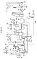
- Figure 2 is a diagramatic representation indicating a similar system to Figure 1, but with a major modification made in the pulverized fuel supply system, in accordance with the present invention.
- Figure 3 is a flow chart showing another version of the method for recovering high-temperature inflammable exhaust gases from the partial combustion of fuel and oxidizer gas, enriched with oxygen gas, in a combustion apparatus with a boiler directly linked thereto, in accordance with the present invention.
- Figure 4 is a perspective view of a typical combustion apparatus for partial combustion of coal, with part broken away to unveil its inside structure.
- a first version of the method of the present invention may be implemented by using part of related facilities for coke oven gas which is unnecessary equipment when the blast furnace have been in shutdown. Because of this, some of the facilities must be used for unintended purposes or left unused at all.
- a combustor apparatus 1 mounted in a horizontal position, comprises a cylindrical chamber having walls which define a reaction zone in the fuel-air mixture is ignited to undergo partial combustion.
- the combustion apparatus 1 carries therein an injection duct 2 through which the fuel-air mixture is injected into the reaction zone.
- the injection duct 2 is mounted to axially tangentially extend to the cylindrical wall of the combustor apparatus for the reason to be explained later.
- the fuel may preferably be pulverized bituminous or subbituminous coal while the oxidizer gas may preferably be air enriched with oxygen gas, blended at a specific percentage to the coal with which it is to be burned in the reaction zone to provide a desired inflammability rate of exhausts.
- An oxygen gas supply 13 is connected to the injection duct 2 through a supply pipe 501 to feed the combustion apparatus 1 with oxygen gas.
- a flow control valve unit 50 may preferably be installed in the supply pipe 501 to control the supply to the injection duct 2.
- the combustor apparatus 1 is also supplied with air through an air passage 12 that extends from a main supply line 102.
- a primary air supply 101 feeds the main supply line with air.
- An forced-draught fan 10 is mounted in the main supply line 102 to move the air therethrough to the injection duct 2.
- a heating device 11 is mounted on the main supply line 102 in such a manner as to heat the air from the primary air source 101.
- a coal hopper 15 feeds bitsuminous or subbituminous coal to a coal pulverizer 17 through a coal silo 16, which in turn grinds the received coal into fine coal particles.
- the pulverized coal is then fed from the exit port of the pulverizer 17 into a pulverized coal silo 21 through a coal line 20, which stores supplied pulverized coal.
- An air passage 19 establishes a fluid flow relation between the pulverizer 17 and the main supply line 102 to supply the pulverizer with part of the air from the primary air source 101.
- a forced-draught mill fan 18 mounted in the air passage 19 to fed the air there through to propel the flow of pulverized coal with it from the pulverizer 17 into the pulverized coal silo 21.
- a nitrogen gas supply 14 feeds nitrogen gas to the pulverized coal silo 21 through a supply line 141 to keep the stored pulverized coal in an inert environment.
- a fuel supply passage 23 interconnects the fuel injection duct 2 and the discharge port of the pulverized coal silo 21 to feed the combustor apparatus 1 with pulverized coal.
- a coal feeder 21a may preferably be mounted at the discharge port of the pulverized coal silo 21 to control the flow of pulverized coal to the injection duct 2 through the fuel supply passage 23.
- the main supply line 102 is connected in fluid flow relationship with the fuel supply passage 23, and supplies part of the air from the primary air supply 101 to mix with the pulverized coal being carried through the coal supply passage to form a air-fuel mixture.
- a forced-draught primary air fan 22 mounted upstream in the fuel supply passage 23 moves the air, heated by the heating device 11, from the primary air supply 101 to the combustor apparatus 1.
- the heat of the air contributes to optimizing the reaction environment of the combustion chamber since the warmed-up air would help heighten fuel burning.
- a burner unit 3 fires the combustor apparatus 1.
- a kerosene source supplies the burner unit 3 with kerosene.
- a pump 25 propels the flow of kerosene to the burner unit 3.
- the burner unit 3 Prior to operation, the burner unit 3 may be fired to heat the combustor apparatus 1 to optimum operating temperature.
- the combustor apparatus employed for partial coal burning according to the present invention may be the type illustrated in U.S. patent 4, 217,132.
- the injection duct 2 supplies the mixture of pulverized bituminous or subbituminous coal from the pulverizer 17, blended with air from the fuel supply passage 23 and oxygen gas from its supply 13.
- the flow of the mixture through the tangential passage of the injection duct 2 develops, upon entering the combustion chamber of the combustor apparatus 1, into a rapidly swirling vortex, as illustrated in Figure 4, and ignites in the heat from the burner unit 3.
- the vortex then undergoes partial combustion, at or near atmospheric pressure, burning at or above the ash fusion temperature, and generates high-temperature inflammable exhaust gases.
- the swirling movement would sustain sufficient residence time of fuel mixture in the combustion chamber enough to optimize burning.
- the molten ash and other non-combustible products present in the mixture while rapidly swirling, would be caused to move outwardly in the reaction zone, eventually forming the outermost portion of the vortex in the combustion chamber.
- the liquid slag thus formed would be allowed to flow down along the curved inside surface of the combustor apparatus 1, and deposit at its bottom where it will be easily taken out through a tapping port 4.
- the generated exhaust gases in the reaction zone will be very high in temperature and inflammable in terms of carbonaceous concentration, containing substantial quantities of incompletely burned by-products such as carbon monoxide and hydrogen, so that the gases can be recovered, after cooling and purification by a filter and a desulfurization unit, for use as useful fuel for boilers, metallurgical or other chemical processes.
- the high-temperature exhaust gases generated will be passed from the combustion apparatus 1 to a heat recovery boiler 27 mounted downstream of it via a coke dry quenching unit 26.
- the heat recovery boiler 27 will use the heat of the received exhaust gases to produce steam.
- the coke dry quenching unit 26 which normally used to gas cool coke, is used only as an intermediate passage interconnected between the combustor apparatus 1 and the heat recovery boiler 27.
- the heat recovery boiler 27 has a steam drum 30, and is connected via a pump 29 to a tank 28 which supplies pure water to the boiler.
- the combustor apparatus 1 will produce exhaust gases of desirably high temperature and desired inflammability from the following operating requirements, which, of course, are suggested by way of illustration alone, and should not be regarded as providing any limitation to the scope of the present invention.
- a set of sensor means may preferably be mounted either at the output areas of the combustor apparatus 1 or the entrance of the heat recovery boiler 27 to check various reaction conditions and the composition of the exhaust gases generated, to send information which may be used for feedback control of fuel, air or oxygen supply through the flow control valve 50 or the fuel feeder 21a.
- a flow control valve now shown, may preferably be installed to control the flow of nitrogen gas through its supply line 141 leading from the supply 14, in response to comparison with one or more of the data obtained from the sensor set. Metered nitrogen gas supply also help optimize stored pulverized coal in an inert conditions.
- the recovered exhaust gases are moved to the cyclone separator 31 that is mounted downstream of the boiler.
- the cyclone separator 31 removes non-combustible substances from the received gases, such as fly ash and dust by the centrifugal effect.
- the cyclone separator 31 is connected at its exit to a four-way valve unit 33 which has three dampers 33a, 33b and 33c in three separate outlets.
- a circulating fan 32 may preferably be mounted to move the cleaned gases from the cyclone separator 31 to the four-way valve unit 33.
- Part of the cleaned gases exiting the cyclone separator 31 is recycled through a recirculating passage 35 back to the coke dry quenching unit 26 where the cooled gases are allowed to blend with the high-temperature exhaust gases, just output from the combustor apparatus 1, moving in their way to the heat recovery boiler 27.
- This recycle is intended to provide control of the boiler operating temperature.
- the majority of the gases from the cyclone separator 31 will be passed via the four-way valve unit damper 33c to a bag filter 37 through a passage 33.
- the bag filter 37 is adapted to filter out the fine dust particles contained in the supplied gases, such as fly ash.
- the emergency damper 33b will be opened to permit the escape of gases into the atmosphere through a primary stack 36.
- a desulfurization unit 39 is connected through a passage 39a to the bag filter 37 to receive the dust-free gases therefrom.
- An induced-draught fan 38 is installed in the passage 39a to move the received gases to the desulfurization unit 39, which removes the sulfur or sulfur compounds contained in the received gases.
- the desulfurization unit 39 is connected at its output to a three-way valve unit 40 which has two dampers 40a and 40b in two separate outlets.
- the three-way valve unit 40 is connected through its damper 40b to a gas recovery passage 41 which in turn leads to a recovery gas tank, not shown, through a recovery valve unit 43 and a V-shaped water sealed valve unit 44.
- the damper 40b is opened, with the other damper 40a closed, to permit the gas flow from the desulfurization unit 39 to the tank, provided the gases generated by the combustor apparatus 1 satisfy desired inflammability requirements for heat recovery. If not, the damper 40b is shut, and the damper 40a is opened to cause the gases from the desulfurization unit 39 to escape into the atmosphere through a secondary stack 42.
- Part of the inflammable gases passed from the damper 40b are carried from the gas recovery passage 41 through a return line 45 to the preheater where the gases supplied are used as fuel.
- the ash and incompletely combusted products, such as carbon monoxides and hydrogen, that come to deposit in trays at the bottom of the coke dry quenching unit 26 and the heat recovery boiler 27, along with those collected from the cyclone separator 31 and the filter 37, such as fly ash and dust particles, are transferred through ash recovery passages to an ash bin 46.
- Figure 2 is a diagramatic view of a heat recovery system similar to Figure 1, but with some changes in the structure, constructed in line with a second version of the method of waste gas recovery according to the present invention.
- Major changes includes the elimination of both the pulverized coal silo 21 and the associated air passage 19 together with its fan 18 to move the pulverized coal from the pulverizer 17 to the silo 21.
- Other elements in the system of Figure 2 are substantially similar to their counterparts of the previous structure, and are referred to by like numbers. Description of these parts is omitted here to avoid unnecessary repetition since they are already explained in association with Figure 1.
- the coal pulverizer 17 is directly coupled to the injection duct 2 through a fuel passage 20, and receives primary air from its source through the air passage 23.
- the paired forced-draught fans 10 and 22 connected in tandem along the passage 23 move the pulverized coal from the pulverizer 17 to the injection duct 2.
- the fuel passage 20′ may also be coupled to the ash bin 46 to receive the ash and incompletely combusted products therefrom and supply them through the injection duct to the combustor apparatus for recombustion with the new streams of pulverized coal from the pulverizer 17.
- the injection duct 2 also receives oxygen gas from its source 13 and primary air, following heating by the preheater 11, from its source 101 through the air passage 12.
- the gases of high inflammability in terms of carbonaceous concentration generated from the partial combustion of pulverized coal and oxidizer gas, enriched with oxygen gas, in a rapidly swirling vortex over a short period of time, are sent to the associated heat recovery boiler 27′ in which the heat of the high-temperature gases may be recovered through a thermal convection surface 48 that forms downstream portion of the boiler. After losing portion of their heat to the thermal convection surface 48 of the heat recovery boiler 27′, the exhaust gases are supplied to the heater 11′ where the residual heat of the received gases is further used to heat the air from the primary air supply 101.
- the gases of high inflammability are then passed to the bag filter 37′ which in turn removes the dust particles from the supplied gases before they are sent to the desulfurization unit 39′.
- the gases after being purified of their sulfur and sulfur compounds by the desulfurization unit 39′, are then passed to a waste gas tank, not shown, moved by the induced-draught fan 38′.
- the damper 40a of the three-way valve unit 40′ is opened to permit them to escape into the atmosphere through the stack 42′, with the other damper 40b closed.
- the damper 40a is shut while the damper 40b is opened to cause the gases to flow through the gas recovery passage 41 into the recovery valve unit 43′ and the water-sealed V-shaped valve unit 44′.
- the received gas from bag filter 37′ are fed to the desulfurization unit 39′ which in turn removes the sulfur compounds or sulfur from the gases.
- the purified gases are then forced by an induced-draught fan 38′ to move toward the three-way valve unit 40′ and then into the gas recovery passage 41.
Landscapes
- Chemical & Material Sciences (AREA)
- Engineering & Computer Science (AREA)
- Combustion & Propulsion (AREA)
- Oil, Petroleum & Natural Gas (AREA)
- Organic Chemistry (AREA)
- Chemical Kinetics & Catalysis (AREA)
- General Chemical & Material Sciences (AREA)
- Mechanical Engineering (AREA)
- General Engineering & Computer Science (AREA)
Description
- The present invention relates to a method of recovering high-temperature inflammable exhaus gases from the partial combustion of fuel and enriched air with oxygen.
- Various combustor apparatus capable of generating high-temperature inflammable exhaust gases containing less non-combustible products, such as ash, suitable to burn a boiler, have been developed. Such gases are recovered from the partial combustion of a mixture of fuel and oxidizer air in a combustor apparatus, which may be designed as the first reaction zone of a boiler system to supply fuel to the second reaction zone. In the first reaction zone, the fuel mixture is burned at or above the slag fusion temperature, generally at atmospheric pressure or near atmospheric pressure, to produce combustible exhaust gases which are recovered and burned in the second reaction zone to produce steam.
- Combustor apparatuses for partial fuel combustion comprise a cylindrical combustion chamber and a tangential injection duct through which fuel mixtures, which may be pulverized coal carried with air, are injected into the combustion chamber. The fuel introduced through the tangential passage of the injection duct, upon entering the combustion chamber, develops into a rapidly swirling vortex. This rapid movement causes most of the ash and other non-combustible products present in the fuel mixture to move externally as molten slag, forming the outermost part of the swirling gaseous stream, and can be expelled from a slagging port mounted at the outside wall of the combustion apparatus. The central portion of the rapidly swirling vortex is recovered from the outlet port of the combustion chamber as high-temperature exhaust gases. The exhaust gases thus obtained contain substantial quantities of incompletely combusted by-products such as carbon monoxide and hydrogen, and are passed to the associated boiler or recycled for other applications.
- However, the boiler would have poor burning on an air-fuel equivalence ratio of lower than 0.6. In conventional methods of exhaust gas recovery from the partial combustion of coal and air, combustion apparatuses have been burned on mixtures of fuel and air as oxidizing gas with an air-fuel equivalence ratio in the range from 0.6 to 0.7. The resultant exhaust gases, recovered following partial combustion in the reaction chamber of the apparatus, have tended to turn out somewhat lacking in inflammability. These recovered gases, which may be used after cooling, have failed to provide efficient thermal energy when burned in a boiler. Experiments showed that the partial combustion at 0.7 air-fuel equivalence ratio produced waste gases of heating value ranging nor more than 200∼500 kcal/Nm³, depending on the kinds of coal making up the fuel mixtures.
- Furthermore, conventional waste gas recovery methods have been proved to pose problems with coal gasification. Generally, requirements for gasification differ from one application to another in which the gases recovered are intended for. For high thermal energy, the gases must have an increased methane content, which means combustion under a pressure of over 20 kg/cm²G. Facilities capable of operation at high reaction pressure levels add much to production costs.
- DE-A-3 531 815 discloses a NOx free boiler using fossil fuel in which "Spaltgas" generated by partial combustion of coal with high temperature air and steam undergoes reburning in a steam of air, to reduce a ceramic catalyst, before it is emitted into the atmosphere.
- The inflammable ingredients of the Spaltgas will all turn to waste gas by catalytic combustion reaction as air is introduced into a combustion chamber. The waste gas will then cool down as it is conducted out through a chimney into the atmosphere. After the combustion chamber, deprived of all the combustible substances, the Spaltgas is no more than a waste gas and is not recoverable for thermal energy, metallurgical or other chemical process.
- As Spaltgas is generated at low temperature using steam as oxidizer gas in a vertical cyclone slag tap gasification chamber, high-temperature air is introduced into the chamber form an air preheater which is mounted in the boiler to insure discharge of molten slag from the chamber.
- In said vertical chamber as the temperature difference between the exhaust gases at the outlet of chamber and the molten slag becomes great, the temperature of the gas has to be raised in operation to insure molten slag discharge. To do this, the air-fuel equivalent ratio needs to be heightened. However, after combustion, the Spaltgas reduces heat value and has a small quantity of inflammable by-products, as it turns into a less useful exhaust gas.
- The object of the present invention is to provide a method of recovering exhaust gases in which generation of an inflammable high-temperature gas is insured, such that the gases recovered can be used to produce steam or, after cooling, re-burned in metallurgical or other chemical processes. This is achieved by the features of claim 1.
- The waste gas recovery method of this invention consists in causing a mixture of pulverized bituminous or sub-bituminous coal and air, enriched with oxygen gas, to undergo partial combustion at or near atmospheric pressure to generate high-temperature exhaust gases containing incompletely burned combustible by-products enough to insure high combustibility. The method insures optimized reaction due to the addition of oxygen has, should the air-fuel equivalence ratio happen to fall short of 0.6.
- The heat of the generated high-temperature gases would be high enough to produce steam in a boiler. After loosing part of their heat to the boiler, the exhaust gases are passed through a filter to remove the ash and other by-products contained in them. The filtered gases are then supplied to a desulfurization unit which in turn removes the sulfur and sulfur compounds from the fed gases before they are recycled as a useful fuel of enough combustibility in terms of carbonaceous concentration for use in boilers, metallurgical or other chemical processes.
- Means are also provided to collect combustible by-products contained in the exhaust gases while they are in the combustion chamber or in a boiler, and recycle them back to the combustion apparatus for re-combustion, upgrading overall combustion efficiency. The recycle not only would reduce the amount of what would otherwise have to be disposed of as unusable slag. Also, reaction in the combustion chamber is such that 90% or more of the non-combustible by-products present in the gases are removed as molten slag more easily than in conventional methods.
- Furthermore, the method of the present invention also increases efficiency because it can enable the exhaust gases from partial combustion to be used as both immediate thermal energy to produce steam, as in a boiler, and subsequent recycle for other applications. In addition, the method provides for easier control of combustion conditions, such as reaction temperature or the inflammability of exhaust gases to be generated in terms of their composition by varying the rate of oxygen gas added to the combustion chamber to be burned with the fuel mixture.
- Figure 1 is a flow diagram explaning a first version of the method for recovering high-temperature inflammable waste gases from the partial combustion of fuel and oxidizer gas, enriched with oxygen gas, in accordance with the present invention.
- Figure 2 is a diagramatic representation indicating a similar system to Figure 1, but with a major modification made in the pulverized fuel supply system, in accordance with the present invention.
- Figure 3 is a flow chart showing another version of the method for recovering high-temperature inflammable exhaust gases from the partial combustion of fuel and oxidizer gas, enriched with oxygen gas, in a combustion apparatus with a boiler directly linked thereto, in accordance with the present invention; and
- Figure 4 is a perspective view of a typical combustion apparatus for partial combustion of coal, with part broken away to unveil its inside structure.
- The method for recovering high-temperature inflammable exhaust gases from the partial combustion of a mixture of pulverized coal and oxidizer gas, enriched with oxygen gas, will be described in detail in conjunction with the accompanying drawings.
- Referring first to Figure 1, a first version of the method of the present invention may be implemented by using part of related facilities for coke oven gas which is unnecessary equipment when the blast furnace have been in shutdown. Because of this, some of the facilities must be used for unintended purposes or left unused at all.
- In the drawing, a combustor apparatus 1, mounted in a horizontal position, comprises a cylindrical chamber having walls which define a reaction zone in the fuel-air mixture is ignited to undergo partial combustion. The combustion apparatus 1 carries therein an
injection duct 2 through which the fuel-air mixture is injected into the reaction zone. Theinjection duct 2 is mounted to axially tangentially extend to the cylindrical wall of the combustor apparatus for the reason to be explained later. - The fuel may preferably be pulverized bituminous or subbituminous coal while the oxidizer gas may preferably be air enriched with oxygen gas, blended at a specific percentage to the coal with which it is to be burned in the reaction zone to provide a desired inflammability rate of exhausts. An
oxygen gas supply 13 is connected to theinjection duct 2 through asupply pipe 501 to feed the combustion apparatus 1 with oxygen gas. A flowcontrol valve unit 50 may preferably be installed in thesupply pipe 501 to control the supply to theinjection duct 2. - The combustor apparatus 1 is also supplied with air through an
air passage 12 that extends from amain supply line 102. Aprimary air supply 101 feeds the main supply line with air. An forced-draught fan 10 is mounted in themain supply line 102 to move the air therethrough to theinjection duct 2. Aheating device 11 is mounted on themain supply line 102 in such a manner as to heat the air from theprimary air source 101. - A coal hopper 15 feeds bitsuminous or subbituminous coal to a
coal pulverizer 17 through acoal silo 16, which in turn grinds the received coal into fine coal particles. The pulverized coal is then fed from the exit port of thepulverizer 17 into a pulverizedcoal silo 21 through acoal line 20, which stores supplied pulverized coal. Anair passage 19 establishes a fluid flow relation between thepulverizer 17 and themain supply line 102 to supply the pulverizer with part of the air from theprimary air source 101. A forced-draught mill fan 18 mounted in theair passage 19 to fed the air there through to propel the flow of pulverized coal with it from thepulverizer 17 into the pulverizedcoal silo 21. - A nitrogen gas supply 14 feeds nitrogen gas to the pulverized
coal silo 21 through asupply line 141 to keep the stored pulverized coal in an inert environment. Afuel supply passage 23 interconnects thefuel injection duct 2 and the discharge port of the pulverizedcoal silo 21 to feed the combustor apparatus 1 with pulverized coal. Acoal feeder 21a may preferably be mounted at the discharge port of the pulverizedcoal silo 21 to control the flow of pulverized coal to theinjection duct 2 through thefuel supply passage 23. Themain supply line 102 is connected in fluid flow relationship with thefuel supply passage 23, and supplies part of the air from theprimary air supply 101 to mix with the pulverized coal being carried through the coal supply passage to form a air-fuel mixture. A forced-draughtprimary air fan 22 mounted upstream in thefuel supply passage 23 moves the air, heated by theheating device 11, from theprimary air supply 101 to the combustor apparatus 1. The heat of the air contributes to optimizing the reaction environment of the combustion chamber since the warmed-up air would help heighten fuel burning. - A
burner unit 3 fires the combustor apparatus 1. A kerosene source supplies theburner unit 3 with kerosene. Apump 25 propels the flow of kerosene to theburner unit 3. Prior to operation, theburner unit 3 may be fired to heat the combustor apparatus 1 to optimum operating temperature. The combustor apparatus employed for partial coal burning according to the present invention may be the type illustrated in U.S. patent 4, 217,132. - The partial combustion of fuel in such an apparatus will be touched upon briefly referring to Figure 4 as well. The
injection duct 2 supplies the mixture of pulverized bituminous or subbituminous coal from the pulverizer 17, blended with air from thefuel supply passage 23 and oxygen gas from itssupply 13. The flow of the mixture through the tangential passage of theinjection duct 2 develops, upon entering the combustion chamber of the combustor apparatus 1, into a rapidly swirling vortex, as illustrated in Figure 4, and ignites in the heat from theburner unit 3. The vortex then undergoes partial combustion, at or near atmospheric pressure, burning at or above the ash fusion temperature, and generates high-temperature inflammable exhaust gases. Furthermore, the swirling movement would sustain sufficient residence time of fuel mixture in the combustion chamber enough to optimize burning. The molten ash and other non-combustible products present in the mixture, while rapidly swirling, would be caused to move outwardly in the reaction zone, eventually forming the outermost portion of the vortex in the combustion chamber. The liquid slag thus formed would be allowed to flow down along the curved inside surface of the combustor apparatus 1, and deposit at its bottom where it will be easily taken out through a tapping port 4. - The generated exhaust gases in the reaction zone will be very high in temperature and inflammable in terms of carbonaceous concentration, containing substantial quantities of incompletely burned by-products such as carbon monoxide and hydrogen, so that the gases can be recovered, after cooling and purification by a filter and a desulfurization unit, for use as useful fuel for boilers, metallurgical or other chemical processes. The high-temperature exhaust gases generated will be passed from the combustion apparatus 1 to a
heat recovery boiler 27 mounted downstream of it via a cokedry quenching unit 26. Theheat recovery boiler 27 will use the heat of the received exhaust gases to produce steam. In the method of this invention, the cokedry quenching unit 26, which normally used to gas cool coke, is used only as an intermediate passage interconnected between the combustor apparatus 1 and theheat recovery boiler 27. - The
heat recovery boiler 27 has asteam drum 30, and is connected via apump 29 to atank 28 which supplies pure water to the boiler. - The combustor apparatus 1 will produce exhaust gases of desirably high temperature and desired inflammability from the following operating requirements, which, of course, are suggested by way of illustration alone, and should not be regarded as providing any limitation to the scope of the present invention.

- A set of sensor means, not shown, may preferably be mounted either at the output areas of the combustor apparatus 1 or the entrance of the
heat recovery boiler 27 to check various reaction conditions and the composition of the exhaust gases generated, to send information which may be used for feedback control of fuel, air or oxygen supply through theflow control valve 50 or thefuel feeder 21a. In addition, a flow control valve, now shown, may preferably be installed to control the flow of nitrogen gas through itssupply line 141 leading from thesupply 14, in response to comparison with one or more of the data obtained from the sensor set. Metered nitrogen gas supply also help optimize stored pulverized coal in an inert conditions. - After loosing portion of their heat to the
heat recovery boiler 27, the recovered exhaust gases are moved to thecyclone separator 31 that is mounted downstream of the boiler. Thecyclone separator 31 removes non-combustible substances from the received gases, such as fly ash and dust by the centrifugal effect. Thecyclone separator 31 is connected at its exit to a four-way valve unit 33 which has threedampers fan 32 may preferably be mounted to move the cleaned gases from thecyclone separator 31 to the four-way valve unit 33. - Part of the cleaned gases exiting the
cyclone separator 31 is recycled through arecirculating passage 35 back to the cokedry quenching unit 26 where the cooled gases are allowed to blend with the high-temperature exhaust gases, just output from the combustor apparatus 1, moving in their way to theheat recovery boiler 27. This recycle is intended to provide control of the boiler operating temperature. The majority of the gases from thecyclone separator 31 will be passed via the four-wayvalve unit damper 33c to abag filter 37 through apassage 33. Thebag filter 37 is adapted to filter out the fine dust particles contained in the supplied gases, such as fly ash. Also, in case of emergency, such as accidental system shutdown or power failure, theemergency damper 33b will be opened to permit the escape of gases into the atmosphere through aprimary stack 36. - A
desulfurization unit 39 is connected through apassage 39a to thebag filter 37 to receive the dust-free gases therefrom. An induced-draught fan 38 is installed in thepassage 39a to move the received gases to thedesulfurization unit 39, which removes the sulfur or sulfur compounds contained in the received gases. Thedesulfurization unit 39 is connected at its output to a three-way valve unit 40 which has twodampers way valve unit 40 is connected through itsdamper 40b to agas recovery passage 41 which in turn leads to a recovery gas tank, not shown, through arecovery valve unit 43 and a V-shaped water sealedvalve unit 44. Thedamper 40b is opened, with theother damper 40a closed, to permit the gas flow from thedesulfurization unit 39 to the tank, provided the gases generated by the combustor apparatus 1 satisfy desired inflammability requirements for heat recovery. If not, thedamper 40b is shut, and thedamper 40a is opened to cause the gases from thedesulfurization unit 39 to escape into the atmosphere through asecondary stack 42. - Part of the inflammable gases passed from the
damper 40b are carried from thegas recovery passage 41 through areturn line 45 to the preheater where the gases supplied are used as fuel. The ash and incompletely combusted products, such as carbon monoxides and hydrogen, that come to deposit in trays at the bottom of the cokedry quenching unit 26 and theheat recovery boiler 27, along with those collected from thecyclone separator 31 and thefilter 37, such as fly ash and dust particles, are transferred through ash recovery passages to anash bin 46. What is collected by theash bin 46 will be transferred through arecycle passage 46a and thefuel passage 23, to which therecycle passage 46a is connected in fluid flow relationship, back into the combustion chamber for re-burning together with the new streams of fuel mixtures supplied into the combustion chamber. A forced-draught fan 47 is mounted to move the flow through therecycle passage 46a into thefuel passage 23. - Figure 2 is a diagramatic view of a heat recovery system similar to Figure 1, but with some changes in the structure, constructed in line with a second version of the method of waste gas recovery according to the present invention. Major changes includes the elimination of both the pulverized
coal silo 21 and the associatedair passage 19 together with itsfan 18 to move the pulverized coal from the pulverizer 17 to thesilo 21. Other elements in the system of Figure 2 are substantially similar to their counterparts of the previous structure, and are referred to by like numbers. Description of these parts is omitted here to avoid unnecessary repetition since they are already explained in association with Figure 1. The coal pulverizer 17 is directly coupled to theinjection duct 2 through afuel passage 20, and receives primary air from its source through theair passage 23. The paired forced-draught fans passage 23 move the pulverized coal from the pulverizer 17 to theinjection duct 2. Thefuel passage 20′ may also be coupled to theash bin 46 to receive the ash and incompletely combusted products therefrom and supply them through the injection duct to the combustor apparatus for recombustion with the new streams of pulverized coal from the pulverizer 17. Theinjection duct 2 also receives oxygen gas from itssource 13 and primary air, following heating by thepreheater 11, from itssource 101 through theair passage 12. The processes after theheat recovery boiler 27, along with the pulverization and supply of coal, are substantially similar to the previously described system, will not be explained for brevity' sake. - Referring then to Figure 3, a further version of the method of waste gas recovery through partial coal combustion in a combustion furnace 1 which is directly coupled to a
heat recovery boiler 27′, will be described in accordance with the present invention. The illustrated system is a simplified modification of Figure 1, and similar components are referred to by like numbers, some of which with an apostrophe attached thereto. Except where parts in Figure 3 differ significantly from their counterparts in Figure 1, they will not be explained here. - The gases of high inflammability in terms of carbonaceous concentration generated from the partial combustion of pulverized coal and oxidizer gas, enriched with oxygen gas, in a rapidly swirling vortex over a short period of time, are sent to the associated
heat recovery boiler 27′ in which the heat of the high-temperature gases may be recovered through athermal convection surface 48 that forms downstream portion of the boiler. After losing portion of their heat to thethermal convection surface 48 of theheat recovery boiler 27′, the exhaust gases are supplied to theheater 11′ where the residual heat of the received gases is further used to heat the air from theprimary air supply 101. - The gases of high inflammability are then passed to the
bag filter 37′ which in turn removes the dust particles from the supplied gases before they are sent to thedesulfurization unit 39′. The gases, after being purified of their sulfur and sulfur compounds by thedesulfurization unit 39′, are then passed to a waste gas tank, not shown, moved by the induced-draught fan 38′. When the exhaust gases output from the combustor apparatus 1 are found to show a desired inflammability, thedamper 40a of the three-way valve unit 40′ is opened to permit them to escape into the atmosphere through thestack 42′, with theother damper 40b closed. When the gases reached the level, thedamper 40a is shut while thedamper 40b is opened to cause the gases to flow through thegas recovery passage 41 into therecovery valve unit 43′ and the water-sealed V-shapedvalve unit 44′. - The ash and incompletely burned combustible products generated by the
heat recovery boiler 27′, theheater 11′ and thebag filter 37′, along with those collected by theash bin 46′, such as fly ash, are recycled through theair passage 23, moved by the forced-draught fan 47′, into the combustor apparatus 1 to be burned, together with the new streams of fuel mixtures introduced into the combustion chamber. The received gas frombag filter 37′ are fed to thedesulfurization unit 39′ which in turn removes the sulfur compounds or sulfur from the gases. The purified gases are then forced by an induced-draught fan 38′ to move toward the three-way valve unit 40′ and then into thegas recovery passage 41.
Claims (3)
- A method of recovering high-temperature inflammable exhaust gases from the partial combustion of fuel and enriched air with oxygen in a combustor apparatus having a substantially horizontally cylindrical reaction chamber and a tangential injection duct (2), the method comprising the steps of;(i) blending a mixture of pulverized coal and enriched air with oxygen as oxidizer gas;(ii) injecting the mixture through the tangetial injection duct to develop a rapidly swirling vortex in the reaction chamber;(iii) igniting the mixture, while rapidly swirling, to undergo partial combustion in the chamber over a short period of time to generate exhaust gases;(iv) mainting the outlet of the chamber at a very high temperature to form an even layer of molten slag along the surface of the combustion chamber;(v) using the sensible heat of the generated exhaust gases by a heat exchange system or boiler (27);(vi) purifying the exhaust gases, after loosing a portion of their heat to the heat exchange, with a filter (37) and a desulfurization unit (39); and(vii) recovering the purified gases after being cooled by loosing their heat for thermal energy and chemical stocks.
- A method as set forth in claim 1 wherein the improvements comprise the step of:
guiding the exhaust gases through an empty vessel in a coke dry quenching unit (26) for heat recovery; and
recovering the gases after being cooled by losing their heat to the heat recovery. - A method as set forth in claim 1, compring the step of varying the rate of oxygen to be blended with said mixture to provide control of partial combustion conditions or of exhaust gas parameters.
Priority Applications (1)
| Application Number | Priority Date | Filing Date | Title |
|---|---|---|---|
| DE1989621485 DE68921485T2 (en) | 1989-12-12 | 1989-12-12 | Process for the recovery of exhaust gas from coal firing. |
Applications Claiming Priority (1)
| Application Number | Priority Date | Filing Date | Title |
|---|---|---|---|
| US07/454,288 US4986199A (en) | 1989-12-21 | 1989-12-21 | Method for recovering waste gases from coal partial combustor |
Publications (2)
| Publication Number | Publication Date |
|---|---|
| EP0432293A1 EP0432293A1 (en) | 1991-06-19 |
| EP0432293B1 true EP0432293B1 (en) | 1995-03-01 |
Family
ID=23804059
Family Applications (1)
| Application Number | Title | Priority Date | Filing Date |
|---|---|---|---|
| EP89122954A Expired - Lifetime EP0432293B1 (en) | 1989-12-12 | 1989-12-12 | Method for recovering waste gases from coal combustor |
Country Status (2)
| Country | Link |
|---|---|
| US (1) | US4986199A (en) |
| EP (1) | EP0432293B1 (en) |
Families Citing this family (15)
| Publication number | Priority date | Publication date | Assignee | Title |
|---|---|---|---|---|
| US5730071A (en) * | 1996-01-16 | 1998-03-24 | The Babcock & Wilcox Company | System to improve mixing and uniformity of furnace combustion gases in a cyclone fired boiler |
| US6968791B2 (en) * | 2003-08-21 | 2005-11-29 | Air Products And Chemicals, Inc. | Oxygen-enriched co-firing of secondary fuels in slagging cyclone combustors |
| US6910432B2 (en) * | 2003-08-21 | 2005-06-28 | Air Products And Chemicals, Inc. | Selective oxygen enrichment in slagging cyclone combustors |
| WO2005033582A1 (en) * | 2003-10-01 | 2005-04-14 | Toshihiro Abe | Combustion system |
| US7736471B2 (en) * | 2005-05-02 | 2010-06-15 | General Atomics | Material treatment systems for waste destruction, energy generation, or the production of useful chemicals |
| US20090084294A1 (en) * | 2006-12-11 | 2009-04-02 | Hamid Sarv | Combustion System and Process |
| US8020499B2 (en) * | 2007-11-09 | 2011-09-20 | Overseas Capital Assets Limited | Apparatus and method for pyrolysis of scrap tyres and the like |
| US7628606B1 (en) * | 2008-05-19 | 2009-12-08 | Browning James A | Method and apparatus for combusting fuel employing vortex stabilization |
| RU2415339C2 (en) * | 2008-05-29 | 2011-03-27 | Мартин ГмбХ Фюр Умвельт-Унд Энергитехник | Combustion plant and control method of combustion plant |
| DE102009031436A1 (en) * | 2009-07-01 | 2011-01-05 | Uhde Gmbh | Method and device for keeping warm coke oven chambers during standstill of a waste heat boiler |
| WO2012122622A1 (en) * | 2011-03-17 | 2012-09-20 | Nexterra Systems Corp. | Control of syngas temperature using a booster burner |
| CN107469579A (en) * | 2017-09-27 | 2017-12-15 | 佛山市深研信息技术有限公司 | A kind of novel environment friendly FGD by spraying mist equipment |
| CN109207205B (en) * | 2018-09-20 | 2024-03-05 | 卢高平 | Fast ignition gas-producing structure of gasification furnace |
| CN112316602A (en) * | 2020-09-05 | 2021-02-05 | 江苏吉能达环境能源科技有限公司 | Desulfurization dust remover that dust collection efficiency is high |
| EP4414647A1 (en) * | 2023-02-08 | 2024-08-14 | Linde GmbH | A method for heating or refining a liquid material in a furnace |
Family Cites Families (9)
| Publication number | Priority date | Publication date | Assignee | Title |
|---|---|---|---|---|
| US3818869A (en) * | 1973-01-02 | 1974-06-25 | Combustion Eng | Method of operating a combined gasification-steam generating plant |
| US4217132A (en) * | 1977-09-27 | 1980-08-12 | Trw Inc. | Method for in-flight combustion of carbonaceous fuels |
| US4272256A (en) * | 1979-10-15 | 1981-06-09 | Koppers Company Inc. | Method for heating oxygen containing gas in conjunction with a gasification system |
| GB8400639D0 (en) * | 1984-01-11 | 1984-02-15 | Shell Int Research | Synthesis gas |
| DE3447147A1 (en) * | 1984-12-22 | 1986-06-26 | Christian Dr.-Ing. 8570 Pegnitz Koch | METHOD AND DEVICE FOR NITROGEN-FREE STEAM GENERATION WITH FOSSILE FUELS |
| US4569680A (en) * | 1984-12-26 | 1986-02-11 | Combustion Engineering | Gasifier with economizer gas exit temperature control |
| JPS62236891A (en) * | 1986-04-09 | 1987-10-16 | Hitachi Ltd | Method and apparatus for gasification in coal gasification oven |
| US4823742A (en) * | 1987-12-11 | 1989-04-25 | Shell Oil Company | Coal gasification process with inhibition of quench zone plugging |
| US4859213A (en) * | 1988-06-20 | 1989-08-22 | Shell Oil Company | Interchangeable quench gas injection ring |
-
1989
- 1989-12-12 EP EP89122954A patent/EP0432293B1/en not_active Expired - Lifetime
- 1989-12-21 US US07/454,288 patent/US4986199A/en not_active Expired - Fee Related
Also Published As
| Publication number | Publication date |
|---|---|
| US4986199A (en) | 1991-01-22 |
| EP0432293A1 (en) | 1991-06-19 |
Similar Documents
| Publication | Publication Date | Title |
|---|---|---|
| JP3203255B2 (en) | Method and apparatus for utilizing biofuel or waste material for energy production | |
| EP0432293B1 (en) | Method for recovering waste gases from coal combustor | |
| US4861262A (en) | Method and apparatus for waste disposal | |
| US3508506A (en) | Process and apparatus for reduction of unburned combustible in fly ash | |
| WO2004092648A1 (en) | Method of controlling combustion of waste incinerator and waste incinerator | |
| US6067916A (en) | Process and device for producing and utilizing gas from waste materials | |
| USRE34298E (en) | Method for waste disposal | |
| JP6653862B2 (en) | Method and ignition device for combustion management in an ignition device | |
| EP0525001A1 (en) | Method and apparatus for reducing emissions of n 2?o when burning nitrogen-containing fuels in fluidized bed reactors. | |
| RU2336465C2 (en) | Method of plasma-coal kindling of boiler | |
| EP0436056B1 (en) | Method and apparatus for partial combustion of coal | |
| JP3770653B2 (en) | Gasification combustion method using fluidized bed furnace | |
| CN101479530B (en) | Oxygen-enhanced combustion of unburned carbon in ash | |
| JPH11270816A (en) | Method and apparatus for reducing dioxin in melting furnace | |
| JP2870675B2 (en) | How to operate the pyrolytic combustion zone | |
| RU2350838C1 (en) | High-temperature cyclone reactor | |
| CA1333973C (en) | Method and apparatus for waste disposal | |
| EP1500875A1 (en) | Method of operating waste incinerator and waste incinerator | |
| JP2004169955A (en) | Waste incinerator and method of operating the same | |
| JP3838699B2 (en) | Cylindrical fluidized bed gasification combustion furnace | |
| JPH10220720A (en) | Low nox combustion method in incineration furnace | |
| RU2128806C1 (en) | Method of burning oil coke | |
| JPS61208420A (en) | Method of combustion in dry retorting distillation gasification furnace | |
| JP2004271039A (en) | Thermal decomposition gasifying melting system | |
| JP5981696B2 (en) | Gasification melting equipment melting furnace |
Legal Events
| Date | Code | Title | Description |
|---|---|---|---|
| PUAI | Public reference made under article 153(3) epc to a published international application that has entered the european phase |
Free format text: ORIGINAL CODE: 0009012 |
|
| 17P | Request for examination filed |
Effective date: 19901107 |
|
| AK | Designated contracting states |
Kind code of ref document: A1 Designated state(s): DE GB IT |
|
| 17Q | First examination report despatched |
Effective date: 19920923 |
|
| GRAA | (expected) grant |
Free format text: ORIGINAL CODE: 0009210 |
|
| AK | Designated contracting states |
Kind code of ref document: B1 Designated state(s): DE GB IT |
|
| REF | Corresponds to: |
Ref document number: 68921485 Country of ref document: DE Date of ref document: 19950406 |
|
| ITF | It: translation for a ep patent filed | ||
| PLBE | No opposition filed within time limit |
Free format text: ORIGINAL CODE: 0009261 |
|
| STAA | Information on the status of an ep patent application or granted ep patent |
Free format text: STATUS: NO OPPOSITION FILED WITHIN TIME LIMIT |
|
| 26N | No opposition filed | ||
| PGFP | Annual fee paid to national office [announced via postgrant information from national office to epo] |
Ref country code: GB Payment date: 19991021 Year of fee payment: 11 |
|
| PGFP | Annual fee paid to national office [announced via postgrant information from national office to epo] |
Ref country code: DE Payment date: 19991223 Year of fee payment: 11 |
|
| PG25 | Lapsed in a contracting state [announced via postgrant information from national office to epo] |
Ref country code: GB Free format text: LAPSE BECAUSE OF NON-PAYMENT OF DUE FEES Effective date: 20001212 |
|
| GBPC | Gb: european patent ceased through non-payment of renewal fee |
Effective date: 20001212 |
|
| PG25 | Lapsed in a contracting state [announced via postgrant information from national office to epo] |
Ref country code: DE Free format text: LAPSE BECAUSE OF NON-PAYMENT OF DUE FEES Effective date: 20011002 |
|
| PG25 | Lapsed in a contracting state [announced via postgrant information from national office to epo] |
Ref country code: IT Free format text: LAPSE BECAUSE OF NON-PAYMENT OF DUE FEES;WARNING: LAPSES OF ITALIAN PATENTS WITH EFFECTIVE DATE BEFORE 2007 MAY HAVE OCCURRED AT ANY TIME BEFORE 2007. THE CORRECT EFFECTIVE DATE MAY BE DIFFERENT FROM THE ONE RECORDED. Effective date: 20051212 |