EP0405984A1 - Antriebsschlupfregelung für Kraftfahrzeuge - Google Patents
Antriebsschlupfregelung für Kraftfahrzeuge Download PDFInfo
- Publication number
- EP0405984A1 EP0405984A1 EP90307101A EP90307101A EP0405984A1 EP 0405984 A1 EP0405984 A1 EP 0405984A1 EP 90307101 A EP90307101 A EP 90307101A EP 90307101 A EP90307101 A EP 90307101A EP 0405984 A1 EP0405984 A1 EP 0405984A1
- Authority
- EP
- European Patent Office
- Prior art keywords
- drive
- wheel
- control mode
- velocity
- circuit
- Prior art date
- Legal status (The legal status is an assumption and is not a legal conclusion. Google has not performed a legal analysis and makes no representation as to the accuracy of the status listed.)
- Granted
Links
Images
Classifications
-
- B—PERFORMING OPERATIONS; TRANSPORTING
- B60—VEHICLES IN GENERAL
- B60T—VEHICLE BRAKE CONTROL SYSTEMS OR PARTS THEREOF; BRAKE CONTROL SYSTEMS OR PARTS THEREOF, IN GENERAL; ARRANGEMENT OF BRAKING ELEMENTS ON VEHICLES IN GENERAL; PORTABLE DEVICES FOR PREVENTING UNWANTED MOVEMENT OF VEHICLES; VEHICLE MODIFICATIONS TO FACILITATE COOLING OF BRAKES
- B60T8/00—Arrangements for adjusting wheel-braking force to meet varying vehicular or ground-surface conditions, e.g. limiting or varying distribution of braking force
- B60T8/32—Arrangements for adjusting wheel-braking force to meet varying vehicular or ground-surface conditions, e.g. limiting or varying distribution of braking force responsive to a speed condition, e.g. acceleration or deceleration
- B60T8/34—Arrangements for adjusting wheel-braking force to meet varying vehicular or ground-surface conditions, e.g. limiting or varying distribution of braking force responsive to a speed condition, e.g. acceleration or deceleration having a fluid pressure regulator responsive to a speed condition
- B60T8/48—Arrangements for adjusting wheel-braking force to meet varying vehicular or ground-surface conditions, e.g. limiting or varying distribution of braking force responsive to a speed condition, e.g. acceleration or deceleration having a fluid pressure regulator responsive to a speed condition connecting the brake actuator to an alternative or additional source of fluid pressure, e.g. traction control systems
-
- B—PERFORMING OPERATIONS; TRANSPORTING
- B60—VEHICLES IN GENERAL
- B60T—VEHICLE BRAKE CONTROL SYSTEMS OR PARTS THEREOF; BRAKE CONTROL SYSTEMS OR PARTS THEREOF, IN GENERAL; ARRANGEMENT OF BRAKING ELEMENTS ON VEHICLES IN GENERAL; PORTABLE DEVICES FOR PREVENTING UNWANTED MOVEMENT OF VEHICLES; VEHICLE MODIFICATIONS TO FACILITATE COOLING OF BRAKES
- B60T8/00—Arrangements for adjusting wheel-braking force to meet varying vehicular or ground-surface conditions, e.g. limiting or varying distribution of braking force
- B60T8/17—Using electrical or electronic regulation means to control braking
- B60T8/175—Brake regulation specially adapted to prevent excessive wheel spin during vehicle acceleration, e.g. for traction control
Definitions
- the field of the present invention is traction control methods for vehicles, comprising producing a braking force in drive-wheel brake devices, when an excessively slipping tendency has occurred in a drive wheel which is in driving operation.
- the prior art methods disclosed include two types: one which independently controls the hydraulic braking pressures for left and right drive-wheel brake devices, and the other which collectively controls the hydraulic braking pressure for the left and right drive-wheel brake devices, both being effected when an excessively slipping tendency has occurred in a drive wheel which is in driving operation.
- the hydraulic braking pressure for the drive-wheel brake devices should be independently controlled in order to rapidly recover the driving force, whereas when an excessively slipping tendency has occurred in the drive wheels in the course of travelling of the vehicle at a relatively high speed, the hydraulic braking pressure for the drive-wheel brake devices should be collectively controlled to maintain the stability of the vehicle.
- the hydraulic braking pressure is controlled in a fixed control mode as in the prior art, no satisfactory result can be achieved in respect of one of the driving force and the stability.
- the present invention has been accomplished with the above circumstances in view, and it is an object of the present invention to provide a traction control method for a vehicle, wherein control modes for the drive-wheel brake devices can be changed between the time when the driving force should be taken more account of and the time when the vehicle stability should be taken more account of, thereby improving the driving force and the stability while maintaining the harmony therebetween.
- an independent control mode for independently controlling the braking forces of a plurality of drive-wheel brake devices and a collective control mode for collectively controlling the braking forces of the drive-wheel brake devices are changeable from one to the other.
- an interference may occur between the drive wheels which are under the traction control and an engine mounted on the vehicle. If target values of drive-wheel velocities are previously set at given levels, a restraint which may reduce the number of revolutions of engine may be applied to the engine side from the drive wheel side.
- the traction control in the independent control mode is effected when the excessively slipping tendency of one of the left and right drive wheels has been increased, there is an increased difference between the actual number of revolutions of the engine and the ideal number of revolutions of the engine which may be evaluated from approximately 1/2 of the sum of the velocities of the left and right drive wheels, resulting in an increased restraint applied to the engine side from the drive wheel side, with a fear that the number of revolutions of the engine may be reduced more than necessary, and/or a control hunting may occur.
- the target values of the drive-wheel velocities in the independent control mode are set larger than those in the collective control mode.
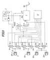
- left and right drive-wheel brake devices B FL and B FR are mounted on left and right front wheels of the vehicle, respectively, and left and right driven-wheel brake devices B RL and B RR are mounted on left and right rear wheels, respectively.
- a hydraulic braking pressure producing means 3 is connected to a brake pedal 1 for controlling the hydraulic pressure from a hydraulic pressure supply source 2 to output in accordance with the amount of brake pedal 1 depressed, so that during a normal braking, the output hydraulic pressure from the hydraulic braking pressure producing means 3 is provided to each of the wheel brake devices B FL , B FR , B RL and B RR .
- the hydraulic braking pressure for the brake devices B FL , B FR , B RL and B RR can be maintained or reduced to effect an anti- lock control by means of flow-in solenoid valves 4 FL and 4 FR and flow-out solenoid valves 5 FL and 5 FR mounted individually in correspondence to the drive-wheel brake devices B FL and B FR as well as flow-in and flow-out solenoid valves 4 R and 5 R mounted commonly for the driven-wheel brake devices B RL and B RR .
- hydraulic braking pressure can be controlled to effect a traction control by means of normally-opened and normally-closed type traction-control solenoid valves 6 and 7 as well as the flow-in solenoid valves 4 FL , 4 FR and flow-out solenoid valves 5 FL , 5 FR .
- the hydraulic pressure supply source 2 comprises a hydraulic pump P for pumping a working oil from a reservoir R, an accumulator A connected to the hydraulic pump P, and a pressure switch S for controlling the operation of the hydraulic pump P.
- the hydraulic braking pressure producing means 3 includes an input port 3a leading to the hydraulic pressure supply source 2, an output port 3b, and a release port 3c leading to the reservoir R and is designed to produce a hydraulic pressure in accordance with the amount of brake pedal 1 depressed from the output port 3b by providing a change-over of the communication between the output port 3b and the input port 3a and the communication between the output port 3b and the release port 3c in response to the depression of the brake pedal 1.
- Each of the brake devices B FL , B FR , B RL and B RR comprises a cylinder body 8 and a braking piston 9 slidably received in the cylinder body 8, so that a braking force is exhibited by the movement of the braking piston 9 in accordance with the hydraulic pressure applied to a braking hydraulic pressure chamber 10 defined between the cylinder body 8 and the braking piston 9.
- the flow-in solenoid valves 4 FL and 4 FR are arranged parallel to the flow-out solenoid valves 5 FL and 5 FR , respectively, and connected to the respective hydraulic braking pressure chambers 10 in the drive-wheel brake devices B FL and B FR , and the flow-in solenoid valve 4 R and the flow-out solenoid valve 5 R are arranged in parallel and connected to the hydraulic braking pressure chambers 10 in the driven-wheel brake devices B RL and B RR .
- the flow-in solenoid valves 4 FL , 4 FR and 4 R are solenoid valves which are adapted to be closed during excitation of solenoids 4 FLS , 4 FRS and 4 RS
- the flow-out solenoid valves 5 FL , 5 FR and 5 R are solenoid valves which are adapted to be opened during excitation of solenoids 5 FLS , 5 FRS and 5 RS .
- the flow-in solenoid valves 4 FL and 4 FR are interposed between the hydraulic braking pressure chambers 10 in the drive-wheel brake devices B FL and B FR and an oil passage 11, while the flow-out solenoid valves 5 FL and 5 FR are interposed between the hydraulic braking pressure chambers 10 in the drive-wheel brake devices B FL and B FR and the reservoir R.
- the flow-in solenoid valve 4 R is interposed between the hydraulic braking pressure chambers 10 in the driven-wheel brake devices B RL and B RR and the output port 3b in the hydraulic braking pressure producing means 3, while the flow-out solenoid valve 4 R is interposed between the hydraulic braking pressure chambers 10 in the driven-wheel brake devices B RL and B RR and the reservoir R.
- the normally-opened type traction control solenoid valve 6 is interposed between the oil passage 11 and the output port 3b in the hydraulic braking pressure producing means 3, while the normally-closed type traction control solenoid valve 7 is interposed between the oil passage 11 and the hydraulic pressure supply source 2.
- the excitation and deexcitation of the respective solenoids 4 FLS , 4 FRS , 4 RS , 5 FLS , 5 FRS , 5 RS , 6 S and 7 S in the solenoid valves 4 FL , 4 FR , 4 R , 5 FL , 5 FR , 5 R , 6 and 7 are controlled by a control means 12, and in a normal condition, the solenoids 4 FLS , 4 FRS , 4 RS , 5 FLS , 5 FRS , 5 RS , 6 S and 7 S are in their deexcited states.
- the flow-in solenoid valves 4 FL , 4 FR and 4 R associated with the wheels which are about to become locked are closed, whereby increasing of the braking force can be suppressed to avoid that the wheels are brought into the locked states. If the wheels are still likely to be locked, the corresponding flow-out solenoid valves 5 FL , 5 FR and 5 R are opened to reduce the braking force, whereby the locking tendency of the wheels is eliminated.
- the hydraulic pressure from the hydraulic pressure supply source 2 is applied to the oil passage 11 by excitation of the solenoids 6 S and 7 S of the normally-opened and normally-closed type traction-control solenoid valves 6 and 7.
- the hydraulic pressure in the oil passage 11 with the solenoids 4 FLS , 4 FRS , 5 FLS and 5 FRS remaining deexcited, is applied to the hydraulic braking pressure chambers 10 in the drive-wheel brake devices B FL and B FR .
- the solenoids 4F LS and 4 FRS are excited with the solenoids 5 FLS and 5 FRS remaining deexcited, thereby maintaining the hydraulic braking pressure in the hydraulic braking pressure chambers 10.
- the solenoids 4 FLS , 4 FRS , 5 FLS and 5 FRS are excited to release the hydraulic pressure in the hydraulic braking pressure chambers 10.
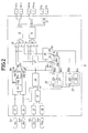
- the control means 12 is operated with a change-over between an independent control mode and a collective control mode. The construction of essential portions of the control means 12 therefor will be described below.
- the control means 12 comprises a left drive-wheel solenoid control circuit 15 connected to the solenoids 4 FLS and 5 FLS of the flow-in and flow-out solenoid valves 4 FL and 5 FL associated with the left drive-wheel brake device B FL , a right drive-wheel solenoid control circuit 16 connected to the solenoids 4 FRS and 5 FRS of the flow-in and flow-out solenoid valves 4 FR and 5 FR associated with the right drive-wheel brake device B FR , an OR circuit 17 having input terminals to which the solenoid control circuits 15 and 16 are connected and an output terminal connected to the solenoids 6 S and 7 S of the normally-opened and normally-closed type solenoid valves 6 and 7, an averaging circuit 18 for averaging left and right drive-wheel velocities V FL and V FR , a first change-over switch 19 for alternatively changing over an averaged drive-wheel velocity V FA averaged in the averaging circuit 18 and the left drive-wheel velocity V FL
- the control means 12 further includes a high select circuit 21 for selecting a higher one of left and right driven-wheel velocities V RL and V RR as a vehicle velocity V R , a collectively-controlling target-velocity determining circuit 22 for determining a drive-wheel target-velocity for the collective control mode on the basis of the vehicle velocity V R provided in the high select circuit 21, an independently-controlling target-velocity determining circuit 23 for determining a drive-wheel target-velocity for the independent control mode on the basis of the vehicle velocity V R , a third 24 and a fourth change-over switch 25 for alternatively changing over one of the target velocities determined in the target-velocity determining circuits 22 and 23 to the other to deliver it, a control mode judging circuit 26 for judging whether either the independent control mode or the collective control mode is to be selected, progressively incresing or decreasing circuits 27 and 28 for progressively increasing or decreasing the target velocities outputted from the third and fourth change-over switches 24 and
- Drive-wheel velocity detecting sensors S FL and S FR are mounted on the left and right front wheels as drive wheels, so that the drive-wheel velocities V FL and V FR are inputted to filters 33 and 34 in the control means 12, respectively.
- Driven-wheel velocity detecting sensors S RL and S RR are also mounted on the left and right rear wheels as driven wheels, so that the driven-wheel velocities V RL and V RR are inputted to filters 35 and 36 in the control means 12, respectively.
- the first change-over switch 19 is adapted to change over the conducting connections of a separate contact 19a connected to the averaging circuit 18 and a separate contact 19b connected to the filter 33 with a common contact 19c in accordance with the output from the control mode judging circuit 26, so that if the output from the control mode judging circuit 26 is at a lower level, the separate contact 19a and the common contact 19c are interconnected into conduction, and if the output from the control mode judging circuit 26 goes into a higher level, the separate contact 19b and the common contact 19c are interconnected into conduction.
- the second change-over switch 20 is adapted to change over the conducting connections of a separate contact 20a connected to the averaging circuit 18 and a separate contact 20b connected to the filter 34 with a common contact 20c in accordance with the output from the control mode judging circuit 26, so that if the output from the control mode judging circuit 26 is at a lower level, the separate contact 20a and the common contact 20c are interconnected into conduction, and if the output from the control mode judging circuit 26 goes into a higher level, the separate contact 20b and the common contact 20c are interconnected into conduction.
- the driven-wheel velocities V RL and V RR with noise removed in the filters 35 and 36 are inputted into the high select circuit 21.
- the high select circuit 21 is adapted to select the higher one of the driven-wheel velocities V RL and V RR to deliver it.
- the collectively-controlling target-velocity determining circuit 22 is adapted to determine the target velocity for the drive wheels uhen the collective control mode has been selected, on the basis of the vehicle velocity V R inputted thereinto from the high select circuit 21, and comprises a higher target-velocity calculating circuit 22 H for calculating a higher target velocity V RHC on the basis of the vehicle velocity V R , and a lower target-velocity calculating circuit 22 L for calculating a lower target velocity V RLC on the basis of the higher target velocity V RHC .
- the independently-controlling target-velocity determining circuit 23 is adapted to determine the target velocity for the drive wheels when the independent control mode has been selected, on the basis of the vehicle velocity V R inputted thereinto from the high select circuit 21, and comprises a higher target-velocity calculating circuit 23 H for calculating a higher target velocity V RHI on the basis of the vehicle velocity V R , and a lower target-velocity calculating circuit 23 L for calculating a lower target velocity V RLI on the basis of the higher target velocity V RHI .
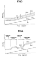
- the target velocities determined in such collectively-controlling target-velocity determining circuit 22 and independently-controlling target-velocity determining circuit 23 are shown as in Fig.3. More specifically, the higher target velocity V RHI for use in the independent control mode is set larger by d H than the higher target velocity V RHC for use in the collective control mode, while the lower target velocity V RLI for use in the independent control mode is set larger by d L than the lower target velocity V RLC for use in the collective control mode. According to the above-described expressions (1) to (4), d H is 5 km/hr, and d L is 4 km/hr.
- the third change-over suitch 24 is adapted to change over, in accordance uith the output from the control mode judging circuit 26, the conducting connections of a separate contact 24a connected to the higher target-velocity calculating circuit 22 H of the collectively-controlling target velocity determining circuit 22 as well as a separate contact 24b connected to the higher target-velocity calculating circuit 23 H of the independently-controlling target-velocity determining circuit 23 with a common contact 24c connected to the progressively increasing or decreasing circuit 27.
- the separate contact 24a and the common contact 24c are interconnected into conduction, and if the output from the control mode judging circuit 26 goes into a higher level, then the separate contact 24b and the common contact 24c are interconnected into conduction.
- the fourth change-over switch 25 is adapted to change over, in accordance with the output from the control mode judging circuit 26, the conducting connections of a separate contact 25a connected to the lower target-velocity calculating circuit 22 L of the collectively-controlling target-velocity determining circuit 22 as well as a separate contact 25b connected to the lower target-velocity calculating circuit 23 L of the independently-controlling target-velocity determining circuit 23 with a common contact 25c connected to the progressively increasing or decreasing circuit 28.
- the separate contact 25a and the common contact 25c are interconnected into conduction, and if the output from the control mode judging circuit 26 goes into a higher level, then the separate contact 25b and the common contact 25c are interconnected into conduction.
- the drive wheel velocities V FL and V FR after noise has been removed and the vehicle velocity V R from the high select circuit 21 are inputted into the control mode judging circuit 26. Then, the control mode judging circuit 26, for example, on the basis of a deviation between the drive-wheel velocities V FL and V FR and the vehicle velocity V R , judges whether driving force should be taken more account of, or vehicle stability should be taken more account of, so that if it is decided that the independent control mode should be selected, then a higher level signal is produced, and if it is decided that the collective control mode should be selected, then a lower level signal is produced.
- the averaged drive-wheel velocity V FA is outputted from the common contact 19c of the first change-over switch 19; the averaged drive-wheel velocity V FA is outputted from the common contact 20c of the second change-over switch 20; the higher target velocity V RHC for the collective control mode is outputted from the common contact 24c of the third change-over switch 24; and the lower target velocity V RLC for the collective control mode is outputted from the common contact 25c of the fourth change-over switch 25.
- the left wheel-drive velocity V FL is outputted from the common contact 19c of the first change-over switch 19; the right drive-wheel velocity V FR is outputted from the common contact 20c of the second change-over switch 20; the higher target velocity V RHI for the independent control mode is outputted from the common contact 24c of the third change-over switch 24; and the lower target velocity V RLI for the independent control mode is outputted from the common contact 25c of the fourth change-over switch 25.
- the progressively increasing or decreasing circuits 27 and 28 are adapted to progressively increase or decrease the target velocity received from the third and fourth change-over switches 24 and 25 upon change-over between the collective and independent control modes. Specifically, upon change-over from the collective control mode to the independent control mode, as shown in Fig.4, i.e., when the signal received into the progressively increasing or decreasing circuits 27 and 28 from the control mode judging circuit 26 has been brought from the lower level into the higher level, the progressively increasing or decreasing circuit 27 stepwise increases the higher target velocity from the value V RHC to the value V RHI , and the progressively increasing or decreasing circuit 28 stepwise increases the lower target velocity from the value V RLC to the value V RLI .
- the progressively increasing or decreasing circuit 27 stepwise decreases the higher target velocity from V RHI to V RHC
- the progressively increasing or decreasing circuit 28 stepwise decreases the lower target velocity from V RLI to V RLC .
- the common contact 19c of the first change-over switch 19 is connected to a non-inverted input terminal of the comparator circuit 29, and the progressively increasing or decreasing circuit 27 is connected to an inverted input terminal of the comparator circuit 29 whose output terminal is connected to the left drive-wheel solenoid control circuit 15.
- the comparator circuit 29 supplies a higher level signal to the left drive-wheel solenoid control circuit 15, when the drive-wheel velocity received from the common contact 19c has exceeded the higher target velocity received from the progressively increasing or decreasing circuit 27.
- the common contact 19c is connected to an inverted input terminal of the comparator circuit 30, and the progressively increasing or decreasing circuit 28 is connected to a non-inverted input terminal of the comparator circuit 30 whose output terminal is connected to the left drive-wheel solenoid control circuit 15.
- the comparator circuit 30 supplies a higher level signal to the left drive-wheel solenoid control circuit 15, when the drive-wheel velocity received from the common contact 19c is equal to or less than the lower target velocity received from the progressively increasing or decreasing circuit 28.
- the comparator circuits 31 and 32 correspond to the comparator circuits 29 and 30, respectively.
- the comparator circuit 31 delivers a higher level signal to the right drive-wheel solenoid control circuit 16, when the drive-wheel velocity received from the common contact 20c has exceeded the higher target velocity received from the progressively increasing or decreasing circuit 27, and the comparator circuit 32 delivers a higher level signal to the right drive-wheel solenoid control circuit 16, when the drive-wheel velocity received from the common contact 20c is equal to or less than the lower target velocity received from the progressively increasing or decreasing circuit 28.
- Each of the left and right drive-wheel solenoid control circuits 15 and 16 is adapted to deliver a signal indicative of a command to control the excitation and deexcitation of the individual solenoids 4 FLS , 4 FRS , 5 FLS , 5 FRS , 6 S , 7 S on the basis of input signals from the corresponding comparator circuits 29, 30; 31, 32, respectively, so that the left and right drive-wheel velocities fall in a range between the higher target velocities V RHC and V RHI and the lower target velocities V RLC and V RLI .
- the control of the excitation and deexcitation of the individual solenoids 4 FLS , 4 FRS , 5 FLS , 5 FRS , 6 S and 7 S can be carried out in the independent control mode in which the hydraulic braking pressures for the left and right drive-wheel brake devices B FL and B FR are independently controlled, when the driving force should be more account of, and in the collective control mode in which the hydraulic braking pressures for the left and right drive-wheel brake devices B FL and B FR are collectively controlled, when the stability should be taken more account of.
- the results of comparison of the left drive-wheel velocity V FL with the higher and lower target velocities V RHI and V RLI for the independent control mode are delivered from the comparator circuits 29 and 30 to the left drive-wheel solenoid control circuit 15, while the results of comparison of the right drive-wheel velocity V FR with the higher and lower target velocities V RHI and V RLI for the independent control mode are delivered from the comparator circuits 31 and 32 to the left drive-wheel solenoid control circuit 16.
- the left drive-wheel solenoid control circuit 15 judges a slipping tendency of the left drive wheel on the basis of the left drive-wheel velocity V FL and produces a control signal for the solenoids 4 FLS , 5 FLS , 6 S and 7 S
- the right drive-wheel solenoid control circuit 16 judges a slipping tendency of the right drive wheel on the basis of the right drive-wheel velocity V FR and produces a control signal for the solenoids 4 FRS , 5 FRS , 6 S and 7 S .
- the results of comparison of the averaged drive-wheel velocity V FA provided in the averaging circuit 18 with the higher and lower target velocities V RHC and V RLC for the collective control mode are inputted into the left and right drive-wheel solenoid control circuits 15 and 16 which then judge the slipping tendency of the drive wheels on the basis of the same drive-wheel velocity V FA and produce control signals for the solenoids 4 FLS , 4 FRS , 5 FLS , 5 FRS , 6 S and 7 S .
- the drive force should be taken more account of than the stability of the vehicle.
- the slipping tendency of the left and right drive wheels are judged independently, and the braking pressure for the drive wheel with an increased slipping tendency is independently increased. This ensures that if the slipping tendency of one of the drive wheels is increased, then the hydraulic braking pressure for one of the left and right drive-wheel brake devices B FL and B FR can be increased, while increasing of the braking force for the other drive wheel can be avoided, thereby ensuring a driving force by a differential limiting effect between the left and right drive wheels.
- the hydraulic braking pressures for the left and right drive-wheel brake devices B FL and B FR are collectively controlled. More specifically, the excessively slipping tendency of the drive wheels is judged on the basis of the averaged value V FA of the left and right drive-wheel velocities, and the hydraulic braking pressures for the drive-wheel brake devices B FL and B FR are controlled in accordance with the result of judgement.
- the change-over is conducted in this manner to select the independent control mode when the driving force should be taken more account of and to select the collective control mode when the stability should be taken more account of, the generation of excessive slipping of the drive wheels can be inhibited with a good sensitivity to ensure the driving force when in the independent control mode, and the hydraulic braking force control leading to the generation of a vibration of the vehicle can be avoided when in the collective control mode.
- each of the velocities of the drive wheels which are being controlled during a tracton control in the independent control mode is controlled to a relatively large value.
- V RHC , V RLC ; V RHI , V RLI of the drive wheels are progressively increased or decreased upon change-over of the collective control mode and the independent control mode, the operation during the change-over can be conducted smoothly.
- the present invention is also applicable to a traction control using both of a control of decreasing the engine output power and the above-described control of the braking forces.
- the traction control by the control of decreasing the engine output power is a collective control whereby the target values of the velocities of the drive wheels are set smaller than the target velocities V RHC and V RLC of the drive wheels provided in the collective control mode by the control of the braking forces.
- the traction deficiency due to the decreasing of the engine output power can be compensated for by the braking force control in the collective control mode.
- the target values in the independent control mode for the braking force control are set larger than ⁇ V R + (target value for the engine output power decreasing control - V R ) x 2 ⁇ , the deficiency due to the engine output power decreasing control can be compensated for by the braking force control during the traction control in the independent control mode.
- the independent control mode may be selected, when the steering angle is equal to or less than a predetermined value, and the collective control mode may be selected, when the steering angle has exceeded the predetermined value.
- the independent control mode may be selected, and when the lateral acceleration has exceeded the predetermined value, the collective control mode may be selected.
- the yaw rate of the vehicle is equal to or less than a predetermined value
- the independent control mode may be selected, and when the yaw rate has exceeded the predetermined value, the collective control mode may be selected.
Landscapes
- Engineering & Computer Science (AREA)
- Physics & Mathematics (AREA)
- Fluid Mechanics (AREA)
- Transportation (AREA)
- Mechanical Engineering (AREA)
- Chemical & Material Sciences (AREA)
- Combustion & Propulsion (AREA)
- Regulating Braking Force (AREA)
Applications Claiming Priority (4)
| Application Number | Priority Date | Filing Date | Title |
|---|---|---|---|
| JP16641489A JP2756503B2 (ja) | 1989-06-28 | 1989-06-28 | 車両の制動油圧制御方法 |
| JP166414/89 | 1989-06-28 | ||
| JP27696/90 | 1990-02-07 | ||
| JP2027696A JP2588785B2 (ja) | 1990-02-07 | 1990-02-07 | 車両のトラクション制御方法 |
Publications (2)
| Publication Number | Publication Date |
|---|---|
| EP0405984A1 true EP0405984A1 (de) | 1991-01-02 |
| EP0405984B1 EP0405984B1 (de) | 1995-08-23 |
Family
ID=26365654
Family Applications (1)
| Application Number | Title | Priority Date | Filing Date |
|---|---|---|---|
| EP19900307101 Expired - Lifetime EP0405984B1 (de) | 1989-06-28 | 1990-06-28 | Antriebsschlupfregelung für Kraftfahrzeuge |
Country Status (2)
| Country | Link |
|---|---|
| EP (1) | EP0405984B1 (de) |
| DE (1) | DE69021793T2 (de) |
Cited By (2)
| Publication number | Priority date | Publication date | Assignee | Title |
|---|---|---|---|---|
| EP0508640A1 (de) * | 1991-04-06 | 1992-10-14 | Lucas Industries Public Limited Company | Antriebsschlupfermittlung und -regelung |
| EP0449333A3 (en) * | 1990-03-30 | 1993-01-27 | Mazda Motor Corporation | Slip control system for automotive vehicle |
Citations (3)
| Publication number | Priority date | Publication date | Assignee | Title |
|---|---|---|---|---|
| FR2509242A1 (fr) * | 1981-07-10 | 1983-01-14 | Daimler Benz Ag | Dispositif de regulation de propulsion de vehicules automobiles |
| EP0265969A2 (de) * | 1986-10-30 | 1988-05-04 | Sumitomo Electric Industries Limited | Vorrichtung zur Begrenzung des Radschlupfes für ein Kraftfahrzeug |
| EP0166178B1 (de) * | 1984-05-26 | 1990-08-08 | Robert Bosch Gmbh | Antriebsschlupfregelsystem |
-
1990
- 1990-06-28 DE DE1990621793 patent/DE69021793T2/de not_active Expired - Fee Related
- 1990-06-28 EP EP19900307101 patent/EP0405984B1/de not_active Expired - Lifetime
Patent Citations (3)
| Publication number | Priority date | Publication date | Assignee | Title |
|---|---|---|---|---|
| FR2509242A1 (fr) * | 1981-07-10 | 1983-01-14 | Daimler Benz Ag | Dispositif de regulation de propulsion de vehicules automobiles |
| EP0166178B1 (de) * | 1984-05-26 | 1990-08-08 | Robert Bosch Gmbh | Antriebsschlupfregelsystem |
| EP0265969A2 (de) * | 1986-10-30 | 1988-05-04 | Sumitomo Electric Industries Limited | Vorrichtung zur Begrenzung des Radschlupfes für ein Kraftfahrzeug |
Cited By (2)
| Publication number | Priority date | Publication date | Assignee | Title |
|---|---|---|---|---|
| EP0449333A3 (en) * | 1990-03-30 | 1993-01-27 | Mazda Motor Corporation | Slip control system for automotive vehicle |
| EP0508640A1 (de) * | 1991-04-06 | 1992-10-14 | Lucas Industries Public Limited Company | Antriebsschlupfermittlung und -regelung |
Also Published As
| Publication number | Publication date |
|---|---|
| EP0405984B1 (de) | 1995-08-23 |
| DE69021793D1 (de) | 1995-09-28 |
| DE69021793T2 (de) | 1996-01-11 |
Similar Documents
| Publication | Publication Date | Title |
|---|---|---|
| EP0943513B1 (de) | Vorrichtung zur Verhaltenssteuerung eines Kraftfahrzeuges mit Hilfe der Bremsen | |
| JP3346041B2 (ja) | アンチスキッド制御装置 | |
| EP0658462B1 (de) | Anti-Blockier Regler | |
| US6023649A (en) | Antiskid controller | |
| JPH09240460A (ja) | 車両の制動制御装置 | |
| JP2725332B2 (ja) | アンチロック制御装置 | |
| JPH07186928A (ja) | 車両走行路面の最大摩擦係数推定装置 | |
| JPH11189138A (ja) | 車両の制動制御装置 | |
| JPH02254051A (ja) | アンチロック制御装置 | |
| JP2841577B2 (ja) | アンチスキツド制御装置 | |
| US5612880A (en) | Process for controlling travel state during braking in vehicle | |
| KR100221107B1 (ko) | 안티-록 제어 장치 | |
| JP2880663B2 (ja) | ブレーキ液圧制御装置 | |
| US5934770A (en) | Brake control system for automotive vehicle | |
| JPH0986377A (ja) | 液圧制御装置 | |
| JPH07205789A (ja) | 四輪駆動車のアンチロックブレーキ制御方法 | |
| US5150950A (en) | Anti-skid brake control method | |
| JP3128883B2 (ja) | アンチスキッド制御装置 | |
| EP0405984B1 (de) | Antriebsschlupfregelung für Kraftfahrzeuge | |
| EP0182374A2 (de) | Anfahrhilfe | |
| JP3248272B2 (ja) | 制動力配分制御装置 | |
| US5269596A (en) | Traction control through collective or independent wheel braking | |
| US6381531B1 (en) | Process and device for adjusting the braking effect in a vehicle | |
| JP3589678B2 (ja) | アンチスキッド制御装置 | |
| JP3554569B2 (ja) | 制動力配分制御装置 |
Legal Events
| Date | Code | Title | Description |
|---|---|---|---|
| PUAI | Public reference made under article 153(3) epc to a published international application that has entered the european phase |
Free format text: ORIGINAL CODE: 0009012 |
|
| AK | Designated contracting states |
Kind code of ref document: A1 Designated state(s): DE GB |
|
| 17P | Request for examination filed |
Effective date: 19910222 |
|
| 17Q | First examination report despatched |
Effective date: 19920416 |
|
| GRAA | (expected) grant |
Free format text: ORIGINAL CODE: 0009210 |
|
| AK | Designated contracting states |
Kind code of ref document: B1 Designated state(s): DE GB |
|
| REF | Corresponds to: |
Ref document number: 69021793 Country of ref document: DE Date of ref document: 19950928 |
|
| PLBE | No opposition filed within time limit |
Free format text: ORIGINAL CODE: 0009261 |
|
| STAA | Information on the status of an ep patent application or granted ep patent |
Free format text: STATUS: NO OPPOSITION FILED WITHIN TIME LIMIT |
|
| 26N | No opposition filed | ||
| REG | Reference to a national code |
Ref country code: GB Ref legal event code: IF02 |
|
| PGFP | Annual fee paid to national office [announced via postgrant information from national office to epo] |
Ref country code: GB Payment date: 20030625 Year of fee payment: 14 |
|
| PG25 | Lapsed in a contracting state [announced via postgrant information from national office to epo] |
Ref country code: GB Free format text: LAPSE BECAUSE OF NON-PAYMENT OF DUE FEES Effective date: 20040628 |
|
| GBPC | Gb: european patent ceased through non-payment of renewal fee |
Effective date: 20040628 |
|
| PGFP | Annual fee paid to national office [announced via postgrant information from national office to epo] |
Ref country code: DE Payment date: 20050623 Year of fee payment: 16 |
|
| PG25 | Lapsed in a contracting state [announced via postgrant information from national office to epo] |
Ref country code: DE Free format text: LAPSE BECAUSE OF NON-PAYMENT OF DUE FEES Effective date: 20070103 |