EP0405853A2 - Armbanduhr mit vibrierendem Alarm - Google Patents
Armbanduhr mit vibrierendem Alarm Download PDFInfo
- Publication number
- EP0405853A2 EP0405853A2 EP90306843A EP90306843A EP0405853A2 EP 0405853 A2 EP0405853 A2 EP 0405853A2 EP 90306843 A EP90306843 A EP 90306843A EP 90306843 A EP90306843 A EP 90306843A EP 0405853 A2 EP0405853 A2 EP 0405853A2
- Authority
- EP
- European Patent Office
- Prior art keywords
- weight
- rotor
- wrist watch
- vibration member
- oscillation
- Prior art date
- Legal status (The legal status is an assumption and is not a legal conclusion. Google has not performed a legal analysis and makes no representation as to the accuracy of the status listed.)
- Withdrawn
Links
Images


Classifications
-
- G—PHYSICS
- G04—HOROLOGY
- G04G—ELECTRONIC TIME-PIECES
- G04G13/00—Producing acoustic time signals
- G04G13/02—Producing acoustic time signals at preselected times, e.g. alarm clocks
- G04G13/021—Details
Definitions
- the present invention relates to a wrist watch having an oscillation alarm.
- an ultrasonic motor having a rotor which is rotated by a travelling-wave which is generated by making use of the expansions and contractions of a piezo-electric element.
- Such an ultrasonic motor needs no reduction gear train or the like partly because it is simply constructed by stacking together planar parts and partly because it has the characteristics of low rotation and a high torque.
- a high torque can be obtained by means of a thin, compact and simple structure.
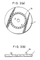
- a rotor 3 has a sliding member 3a adhered thereto which contacts the comb-like projections 1a of the vibration member 1.
- the rotor 3 is integrally formed with a semicircular ridge 3b at its outer circumferential portion to offset the centre of gravity of the rotor 3 from the centre of rotation thereof.
- the eccentric centre of gravity is moved to oscillate the whole structure including a plate 8.
- the comb-like projections 1a may be composed of a series of undulations which are made of a highly rigid metal so as to enhance the rotational performance.
- the sliding member 3a may also be made of a resin or the like so as to enhance the rotational performance.
- a wrist watch characterized by being provided with an oscillation motor comprising a vibration member provided with a piezo-electric element; a rotor having a rotor portion which engages a portion of the vibration member so that energization of the piezo-electric element causes rotation of the rotor; and a weight which is connected by shock-absorbing means to a part of the rotor which is eccentric to the axis of rotation of the latter, whereby energization of the piezo-electric element causes oscillations due to the shifting of the centre of gravity of the weight so as to provide an alarm.
- limit means which are engageable by the weight so as to limit movement of the latter; the shock-absorbing means, when the weight engages the limit means, reducing the risk of damage between the rotor portion and the vibration member portion.
- the limit means may comprise a rigid member having a portion or having abutment means engageable with a portion of the weight on the side of the latter remote from the said part of the rotor.
- the said rigid member portion or the said abutment means may have a part disposed adjacent to a circumferential side surface of the weight.
- the shock-absorbing means may comprise a first shock absorber sandwiched between the weight and the rotor; a weight holder which is secured to or integral with the rotor and which is arranged to support the weight; and a second shock absorber sandwiched between the weight and the weight holder.
- the rotor portion may be arranged to slide on comb-like projections of the vibration member.
- Pressure-exerting means may be provided for pressing the rotor portion and the vibration member portion into contact with each other.
- the weight may be connected to the rotor at the outer circumferential portion of the latter.
- Cover means may be provided to cover at least part of a gap or gaps between the oscillation motor and surrounding structure so as to impede the entry of dust into the gap or gaps.
- the cover means may be constituted by a part of the first shock absorber.
- the oscillation motor may be disposed in an aperture in a dial of the watch.
- the sliding rotor portion is protected from pressure-induced damage even if the watch suffers an impact, e.g. from a fall.
- the reliability of the oscillation motor is improved either by enlarging the first shock absorber, which is sandwiched between the rotor and the weight and which may be made of rubber or a synthetic resin, so as to cover the gap between the rotor, the weight and the vibration member on the one hand and a plate on the other hand, or by providing a dust-proof member.
- the weight may move while compressing and deforming the shock absorbers, if an impact such as a fall is received, until the weight comes into abutment with the limit means to receive the impact wholly. Only a small amount of force will therefore be applied to the contacting parts of the sliding rotor portion and the comb-like projections, so that no pressure-induced damage from the comb-like projections is left in the sliding rotor portion. Consequently, the rotational performance of the motor is not adversely affected in the least.
- the eccentricity (i.e. the primary moment) of the weight will be at its maximum so that the oscillations are felt the most. This will be so if the weight protrudes downwards from the vibration member base at the diameterical outside of the vibration member so as to abut against the plate.
- FIGS 1 and 2 there is shown a first embodiment of wrist watch according to the present invention which comprises a vibration member 1 which has a piezo-electric element 2 adhered thereto on one side thereof and which is formed with comb-like projections 1a on its opposite side.
- a rotor 3 has a sliding member 3a adhered thereto which contacts the comb-like projections 1a of the vibration member 1 so that, when the piezo-electric element 2 is energized (by means not shown), rotation is effected of the rotor 3.
- the first shock absorber 4 is sandwiched between the weight 5 and the rotor 3, the second shock absorber 4e being sandwiched between the weight 5 and the weight holder 6. Since the weight 5 is arranged at the outer circumferential portion of the rotor 3, the position of its centre of gravity will be eccentric to the center of gravity of the rotor 3 and thus of the oscillation motor of which the rotor 3 forms part.
- the weight holder 6, which is disposed on the side of the weight 5 remote from the rotor 3, has a stem 6a which extends through holes in the shock absorbers 4, 4a and in the weight 5, the weight holder 6 being fixed to the rotor 3.
- a pin or spindle 7 supports the vibration member 1 and provides a central axis of rotation of the rotor 3, the spindle 7 being anchored in a plate 8.
- the plate 8 is formed with a ridge 8a which is spaced at a suitable clearance A from the weight 5.
- the clearance A has to be larger than the clearance between the weight 5 and the vibration member 1 and has to be made so small that the shock absorbers 4, 4e are compressed if a force is applied to the weight 5 so that if there is abutment between the weight 5 and the ridge 8a this will not cause any damage between the sliding member 3a and the comb-like projections 1a.
- the rotor 3 is forced into contact with the vibration member 1 by a pressure spring 9, the latter being held in position by a holding seat 10 which is fixed to the pin 7 by a screw 11.
- the arrangement described above constitutes an ultrasonic motor in which in operation an electric signal is applied to the piezo-electric element 2 to generate mechanical travelling-waves in the vibration member 1 so that the rotor 3 is rotated.
- Such rotation of the rotor 3 causes oscillations due to the shifting of the centre of gravity of the weight 5 so as to provide a silent alarm.
- the clearance A is retained so that the rotor 3 and the weight 5 which is secured to the latter can be rotated to oscillate the movement (not shown) of the wrist watch as a result of the movement of the centre of gravity of the weight 5, thus informing the user of the wrist watch.
- a fairly strong force is applied to the weight 5, e.g.
- the shock absorbers 4, 4e are compressed to reduce the clearance A.
- the clearance A disappears to bring the weight 5 into abutment against the ridge 8a.
- the ridge 8a limits relative movement between the weight 5 and the vibration member 1. Since the plate 8 can be conceived here substantially as a rigid member, the external force acting upon the weight 5 can be completely borne.
- the inertia force F1 would be wholly exerted upon the sliding member 3a or on the spindle 7.
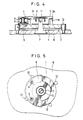
- Figure 4 and Figure 5 show a second embodiment of the present invention in which the ridge 8a of the plate 8 of the first embodiment is replaced by limit pins 12 which are anchored in the plate 8 and which can be engaged by the weight 5.
- the plurality of limit pins 12 are arranged circumferentially along the locus of rotation of the weight 5.
- the means for preventing pressure-induced damage due to a falling impact or the like is absolutely similar to that of the embodiment of Figures 1 and 2, but there is no necessity to form the ridge 8a on the plate 8, so that the cutting of the plate 8 can be simplified and production costs can be reduced.
- means for limiting movement of the weight 5 with an absolutely similar action can be constituted not only by the limit pins 12 but also by an arrangement of rigid parts such as a second plate, a train wheel bridge or a circuit board seat such as are used in an ordinary wrist watch.
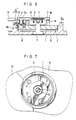
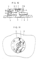
- Figure 6 and Figure 7 show a third embodiment of the present invention having a spindle 7 which supports the vibration member 1 and provides a central axis of rotation of the rotor 3, the spindle 7 being anchored in a plate 8.
- the plate 8 is formed with a two-stepped ridge 8a spaced at a suitable clearance A from the lower side of the weight 5 and from the outer circumference of the latter.
- the clearance A has to be smaller than a clearance B between the weight 5 and the vibration member 1 in the vertical direction
- a clearance A′ between the weight 5 and a step 8b of the ridge 8a has to be smaller than a clearance B′ between the weight 5 and another part (such as a circuit board 13) in the horizontal direction.
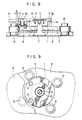
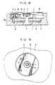
- Figure 8 and Figure 9 show a fourth embodiment of the present invention in which the ridge 8a of the third embodiment is replaced by limit pins 12 which are anchored in the plate 8 and which can be engaged by the weight 5.
- the plurality of limit pins 12 are arranged circumferentially along the locus of rotation of the weight 5.
- the means for preventing pressure-induced damage due to a falling impact or the like is absolutely similar to that of the embodiment of Figure 1 and Figure 2, but there is no necessity to form the ridge 8a on the plate 8 so that the cutting of the plate 8 can be simplified and production costs can be reduced.
- means for limiting movement of the weight 5 with an absolutely similar action can be constituted not only by the limit pins 12 but also by an arrangement of rigid parts such as a second plate, a train wheel bridge or a circuit board seat such as are used in an ordinary wrist watch.
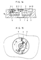
- FIG 10 and Figure 11 show a fifth embodiment of the present invention in which the weight 5 is arranged in a semi-circular or arcuate shape at the outside of comb-like projections 1b of the vibration member 1.
- the weight 5 has a thickness to form a clearance B from the upper face of the base 1c of the vibration member 1 radially inwardly from the periphery of the latter.
- the weight 5 also has a thickness to protrude from the lower face of the base 1c radially outwardly of the latter, thereby to retain a clearance A from the plate 8.
- the clearance A has to be larger than the clearance B between the weight 5 and the vibration member 1 and has to be made so small that the shock absorbers 4 are compressed if there is abutment between the weight 5 and the plate 8 so that the sliding member 3a is prevented from being damaged by the weight 5.
- the weight 5 for oscillating the wrist watch so as to provide an oscillation alarm is separated from the rotor 3 and is attached to the latter through shock absorbing means, and the limit means 8, 8a, 12 are disposed in the vicinity of the weight 5.
- the performance of the ultrasonic motor can be prevented from being adversely affected by a falling impact or the like.
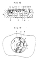
- Figure 12 and Figure 13 show a sixth embodiment of the present invention in which the weight 5 is formed into a sector shape of 1/4 to 2/3 (i.e. 90° to 240°) so as to have an eccentric centre of gravity, there being gaps between the vibration member 1, the rotor 3, the weight 5 and the plate 8.
- the shock absorber 4 is formed with an extension 4a for covering the side gap. Since the side gap can be covered with the extension 4a of the aforementioned shock absorber 4, dust or the like is substantially prevented from entering said side gap so that the oscillation motor can be prevented from being stopped by the dust or the like, whereby its reliability is improved.
- the shock absorber 4 is formed with the extension 4a and with a side portion 4b to further fill the side gap so as to make it more difficult for dust or the like to enter the side gap. As a result, it is possible to provide a structure for improving the reliability of the oscillation motor.
- the shock absorber 4 is formed with a side portion 4b and with an extension 4c in the vicinity of the vibration member 1, and is also formed at its central portion with an aperture 4d. Since the pressure contact between the comb-like projections 1a of the vibration member 1 and the sliding member 3a of the rotor 3 can thus be confirmed, the spring force of the pressure spring 9 can be easily adjusted to reduce any variation in the performance of the oscillation motor while preventing the entry of the dust or the like.
- a dustproof or cover member 15 which extends over the vibration member 1, the rotor 3 and the weight 5.
- the cover member 15 covers the oscillation motor and most of the gap which is formed between the vibration member 1, the rotor 3 and the weight 5 on the one hand and the plate 8 on the other hand.
- a reliable oscillation motor which is protected from the entry of dust or the like. If the cover member 15 has its top face printed or engraved, a decorative oscillation motor can be provided.
- an oscillation motor structure for an electronic wrist watch having a silent alarm can be provided such that the shock absorber 4, 4a or the cover member 15 covers the side gap which is defined by the vibration member 1, the rotor 3 and the weight 5 on the one hand and the plate 8 on the other hand.
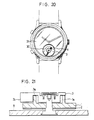
- FIG 20 shows a wrist watch with an oscillation alarm according to the present invention.
- the watch has an ultrasonic motor 30 disposed in an opening in a dial 31. Accordingly, the rotation of the ultrasonic motor can be observed from the dial side of the watch.
Landscapes
- Physics & Mathematics (AREA)
- General Physics & Mathematics (AREA)
- General Electrical Machinery Utilizing Piezoelectricity, Electrostriction Or Magnetostriction (AREA)
- Apparatuses For Generation Of Mechanical Vibrations (AREA)
- Electric Clocks (AREA)
- Electromechanical Clocks (AREA)
Applications Claiming Priority (8)
| Application Number | Priority Date | Filing Date | Title |
|---|---|---|---|
| JP7457689U JPH0314488U (de) | 1989-06-26 | 1989-06-26 | |
| JP74576/89U | 1989-06-26 | ||
| JP5754/90U | 1990-01-24 | ||
| JP575490U JPH0397392U (de) | 1990-01-24 | 1990-01-24 | |
| JP1303090U JPH03106488U (de) | 1990-02-13 | 1990-02-13 | |
| JP13030/90U | 1990-02-13 | ||
| JP15113/90U | 1990-02-16 | ||
| JP1511390U JPH03109095U (de) | 1990-02-16 | 1990-02-16 |
Publications (2)
| Publication Number | Publication Date |
|---|---|
| EP0405853A2 true EP0405853A2 (de) | 1991-01-02 |
| EP0405853A3 EP0405853A3 (en) | 1992-01-22 |
Family
ID=27454356
Family Applications (1)
| Application Number | Title | Priority Date | Filing Date |
|---|---|---|---|
| EP19900306843 Withdrawn EP0405853A3 (en) | 1989-06-26 | 1990-06-22 | Wrist watch with oscillation alarm |
Country Status (2)
| Country | Link |
|---|---|
| US (1) | US5043956A (de) |
| EP (1) | EP0405853A3 (de) |
Families Citing this family (8)
| Publication number | Priority date | Publication date | Assignee | Title |
|---|---|---|---|---|
| JP3015090B2 (ja) * | 1990-10-05 | 2000-02-28 | キヤノン株式会社 | 振動波駆動装置 |
| EP0547250B1 (de) * | 1991-07-05 | 1995-12-13 | Citizen Watch Co. Ltd. | Geräuschlose Weckeruhr |
| JPH05281370A (ja) * | 1992-03-31 | 1993-10-29 | Seiko Instr Inc | アナログ電子時計 |
| CH685660B5 (fr) * | 1992-09-09 | 1996-03-15 | Asulab Sa | Piece d'horlogerie pourvue de moyens d'entraînement formes par un moteur piezo-electrique. |
| JP3107933B2 (ja) * | 1992-12-03 | 2000-11-13 | キヤノン株式会社 | 振動波駆動装置および振動波駆動装置を備えた装置 |
| US6765334B1 (en) * | 1999-09-21 | 2004-07-20 | Seiko Instruments Inc. | Linear or pivotal motion mechanism using ultrasonic motor and electronic device equipped with linear or pivotal motion mechanism |
| ATE544098T1 (de) * | 2008-04-15 | 2012-02-15 | Montres Jaquet Droz Sa | STOßDÄMPFER FÜR SCHWUNGMASSE |
| US9830783B1 (en) | 2014-09-24 | 2017-11-28 | Apple Inc. | Output devices for fabric-based electronic equipment |
Family Cites Families (9)
| Publication number | Priority date | Publication date | Assignee | Title |
|---|---|---|---|---|
| US4192035A (en) * | 1978-11-08 | 1980-03-11 | Ultrasonic Plaque Control Laboratories, Inc. | Ultrasonic toothbrush |
| JPS6089791A (ja) * | 1983-10-24 | 1985-05-20 | Seikosha Co Ltd | アラ−ム腕時計 |
| JPS60111178A (ja) * | 1983-11-21 | 1985-06-17 | Seiko Epson Corp | 指針表示式電子時計 |
| DE3401735C1 (de) * | 1984-01-19 | 1985-05-02 | Herbert 7909 Bollingen Gässler | Vorrichtung zum Betrieb eines piezoelektrischen Ultraschallwandlers |
| JPS6135388A (ja) * | 1984-07-27 | 1986-02-19 | Casio Comput Co Ltd | プリンタ付電子腕時計 |
| US4739212A (en) * | 1985-07-19 | 1988-04-19 | Matsushita Electric Industrial Co., Ltd. | Ultrasonic motor |
| JP2595950B2 (ja) * | 1987-01-27 | 1997-04-02 | 松下電器産業株式会社 | 超音波モータ駆動装置 |
| FR2612267B1 (fr) * | 1987-03-13 | 1989-07-21 | Total France | Dispositif pour le maintien en position d'une extremite d'un element monte mobile en rotation dans un tube et application de ce dispositif |
| US5023853A (en) * | 1988-06-27 | 1991-06-11 | Masayuki Kawata | Electric apparatus with silent alarm |
-
1990
- 1990-06-15 US US07/539,724 patent/US5043956A/en not_active Expired - Fee Related
- 1990-06-22 EP EP19900306843 patent/EP0405853A3/en not_active Withdrawn
Also Published As
| Publication number | Publication date |
|---|---|
| US5043956A (en) | 1991-08-27 |
| EP0405853A3 (en) | 1992-01-22 |
Similar Documents
| Publication | Publication Date | Title |
|---|---|---|
| US4510484A (en) | Piezoelectric reed power supply for use in abnormal tire condition warning systems | |
| US4517841A (en) | Accelerometer with beam resonator force transducer | |
| EP0405853A2 (de) | Armbanduhr mit vibrierendem Alarm | |
| US5646469A (en) | Vibration driven motor including a vibration member having an elastic contact portion and a contact member having an elastic contact portion | |
| US10295960B2 (en) | Striking or musical timepiece with a resonant bezel | |
| JP3837157B2 (ja) | 電気−機械振動変換器 | |
| EP0740353B1 (de) | Vibrationswellengetriebene Anordnung und Vibrationselement | |
| US5365497A (en) | Silent electromagnetic alarm | |
| JP2000078790A (ja) | 電磁振動体及びそれを用いた電池駆動機器 | |
| JP2002311161A (ja) | 偏心錘付時計 | |
| JP2002219413A (ja) | 多機能振動アクチュエータ | |
| KR100410969B1 (ko) | 다기능 액츄에이터 | |
| JPH11223676A (ja) | 小型の機構を駆動する振動おもりの加速度を制限する装置 | |
| CN114362468B (zh) | 振动装置及电子设备 | |
| JP3721740B2 (ja) | 動力伝達機構および電子時計 | |
| KR100370639B1 (ko) | 멀티 액츄에이터 | |
| JP2023050098A (ja) | 計時器用ムーブメントのための保護リング、及び保護リングを備える計時器用ムーブメント | |
| JP2727168B2 (ja) | 振動モータ、振動モータが組み込まれるケーシング、並びに振動モータが組み込まれる振動発生装置 | |
| US5834878A (en) | Vibration wave driving device and apparatus having the same | |
| US4445113A (en) | Small type acoustic device | |
| JPH0453596Y2 (de) | ||
| JP3533910B2 (ja) | 電子時計 | |
| JP2001025204A (ja) | 電磁振動体およびそれを用いた電池駆動機器 | |
| SU1401285A1 (ru) | Пьезоакселерометр | |
| KR950004957B1 (ko) | 전자기 공진 진동기 |
Legal Events
| Date | Code | Title | Description |
|---|---|---|---|
| PUAI | Public reference made under article 153(3) epc to a published international application that has entered the european phase |
Free format text: ORIGINAL CODE: 0009012 |
|
| AK | Designated contracting states |
Kind code of ref document: A2 Designated state(s): CH DE GB LI |
|
| PUAL | Search report despatched |
Free format text: ORIGINAL CODE: 0009013 |
|
| AK | Designated contracting states |
Kind code of ref document: A3 Designated state(s): CH DE GB LI |
|
| STAA | Information on the status of an ep patent application or granted ep patent |
Free format text: STATUS: THE APPLICATION IS DEEMED TO BE WITHDRAWN |
|
| 18D | Application deemed to be withdrawn |
Effective date: 19920723 |