EP0405667A1 - Getriebe, Motorantrieb mit einem derartigen Getriebe sowie Rad für ein derartiges Getriebe oder einen derartigen Motorantrieb - Google Patents
Getriebe, Motorantrieb mit einem derartigen Getriebe sowie Rad für ein derartiges Getriebe oder einen derartigen Motorantrieb Download PDFInfo
- Publication number
- EP0405667A1 EP0405667A1 EP90201643A EP90201643A EP0405667A1 EP 0405667 A1 EP0405667 A1 EP 0405667A1 EP 90201643 A EP90201643 A EP 90201643A EP 90201643 A EP90201643 A EP 90201643A EP 0405667 A1 EP0405667 A1 EP 0405667A1
- Authority
- EP
- European Patent Office
- Prior art keywords
- wheel
- transmission system
- segment
- belt
- motor
- Prior art date
- Legal status (The legal status is an assumption and is not a legal conclusion. Google has not performed a legal analysis and makes no representation as to the accuracy of the status listed.)
- Granted
Links
- 230000005540 biological transmission Effects 0.000 title claims abstract description 84
- 238000006073 displacement reaction Methods 0.000 abstract description 4
- 230000000694 effects Effects 0.000 abstract description 4
- 238000004519 manufacturing process Methods 0.000 abstract description 4
- 239000002184 metal Substances 0.000 description 6
- 229910000831 Steel Inorganic materials 0.000 description 3
- 239000010959 steel Substances 0.000 description 3
- 230000005489 elastic deformation Effects 0.000 description 2
- 238000005452 bending Methods 0.000 description 1
- 239000000463 material Substances 0.000 description 1
- 238000000034 method Methods 0.000 description 1
- 230000035939 shock Effects 0.000 description 1
- 230000003068 static effect Effects 0.000 description 1
- 229920002994 synthetic fiber Polymers 0.000 description 1
- 238000004804 winding Methods 0.000 description 1
Images


Classifications
-
- F—MECHANICAL ENGINEERING; LIGHTING; HEATING; WEAPONS; BLASTING
- F16—ENGINEERING ELEMENTS AND UNITS; GENERAL MEASURES FOR PRODUCING AND MAINTAINING EFFECTIVE FUNCTIONING OF MACHINES OR INSTALLATIONS; THERMAL INSULATION IN GENERAL
- F16G—BELTS, CABLES, OR ROPES, PREDOMINANTLY USED FOR DRIVING PURPOSES; CHAINS; FITTINGS PREDOMINANTLY USED THEREFOR
- F16G1/00—Driving-belts
- F16G1/28—Driving-belts with a contact surface of special shape, e.g. toothed
-
- F—MECHANICAL ENGINEERING; LIGHTING; HEATING; WEAPONS; BLASTING
- F16—ENGINEERING ELEMENTS AND UNITS; GENERAL MEASURES FOR PRODUCING AND MAINTAINING EFFECTIVE FUNCTIONING OF MACHINES OR INSTALLATIONS; THERMAL INSULATION IN GENERAL
- F16H—GEARING
- F16H55/00—Elements with teeth or friction surfaces for conveying motion; Worms, pulleys or sheaves for gearing mechanisms
- F16H55/02—Toothed members; Worms
- F16H55/14—Construction providing resilience or vibration-damping
- F16H55/16—Construction providing resilience or vibration-damping relating to teeth only
-
- F—MECHANICAL ENGINEERING; LIGHTING; HEATING; WEAPONS; BLASTING
- F16—ENGINEERING ELEMENTS AND UNITS; GENERAL MEASURES FOR PRODUCING AND MAINTAINING EFFECTIVE FUNCTIONING OF MACHINES OR INSTALLATIONS; THERMAL INSULATION IN GENERAL
- F16H—GEARING
- F16H55/00—Elements with teeth or friction surfaces for conveying motion; Worms, pulleys or sheaves for gearing mechanisms
- F16H55/02—Toothed members; Worms
- F16H55/17—Toothed wheels
- F16H55/171—Toothed belt pulleys
-
- F—MECHANICAL ENGINEERING; LIGHTING; HEATING; WEAPONS; BLASTING
- F16—ENGINEERING ELEMENTS AND UNITS; GENERAL MEASURES FOR PRODUCING AND MAINTAINING EFFECTIVE FUNCTIONING OF MACHINES OR INSTALLATIONS; THERMAL INSULATION IN GENERAL
- F16H—GEARING
- F16H7/00—Gearings for conveying rotary motion by endless flexible members
- F16H7/02—Gearings for conveying rotary motion by endless flexible members with belts; with V-belts
- F16H7/023—Gearings for conveying rotary motion by endless flexible members with belts; with V-belts with belts having a toothed contact surface or regularly spaced bosses or hollows for slipless or nearly slipless meshing with complementary profiled contact surface of a pulley
-
- F—MECHANICAL ENGINEERING; LIGHTING; HEATING; WEAPONS; BLASTING
- F16—ENGINEERING ELEMENTS AND UNITS; GENERAL MEASURES FOR PRODUCING AND MAINTAINING EFFECTIVE FUNCTIONING OF MACHINES OR INSTALLATIONS; THERMAL INSULATION IN GENERAL
- F16H—GEARING
- F16H7/00—Gearings for conveying rotary motion by endless flexible members
- F16H7/08—Means for varying tension of belts, ropes, or chains
- F16H2007/0876—Control or adjustment of actuators
- F16H2007/0887—Control or adjustment of actuators the tension being a function of load
Definitions
- the invention relates to a transmission system comprising two wheels and an endless belt wound around the wheels.
- the invention further relates to a motor drive comprising such a transmission system and to a belt and a wheel for such a transmission system or motor drive.
- a transmission system of the kind to which the present invention relates is know inter alia from the handbook "Taschenbuch fur den Maschinenbau", Dubbel, 1986, pp. 437 and 438, in various embodiments.
- Such a transmission system serves for the transmission of mechanical power between two or more wheels with parallel axes of rotation by means of an endless belt wound around the wheels.
- the various embodiments can be subdivided into two main groups.
- form-locking transmission systems These are transmission systems which transmit power in that elements of the belt and a wheel are in engagement with each other.
- the expression “positive transmission system” is also used in the relevant literature.
- An example of a form-locking transmission system is a toothed belt transmission system, in which the teeth of a toothed belt and of a toothed wheel are in engagement with each other, as a result of which power is transmitted.
- Disadvantages of form-locking transmission systems are the occurrence of clearance, a comparatively limited stiffness and a non-uniform running due to the so-called polygon effect.
- Most of the form-locking transmission systems can otherwise be made free of clearance, however, though at a comparatively high cost price. However, the two remaining disadvantages still subsist.
- friction-locking or force-locking transmission systems are transmission systems which transmit power in that in operation friction occurs between parts of the belt and the wheel.
- An example is a steel belt transmission system comprising an endless steel belt, which is wound with pre-stress around the wheels. In this case, the power is transmitted by friction between the belt and a wheel.
- This steel belt transmission system has a comparatively high stiffness and does not exhibit a polygon effect.
- due to the fact that the belt slips over the wheels after a number of revolutions of a wheel the number of revolutions of another wheel in the transmission system cannot be defined unambiguously.
- the transmission ratio of a friction-locking transmission system is thus not unambiguously known.
- the invention has for its object to provide a transmission system of the kind described in the opening paragraph, in which an unambiguous transmission ratio is defined whilst maintaining a sufficient mechanical stiffness.
- this object is achieved in that each wheel is subdivided into segments which are displaceable against spring force in the tangential direction of the wheel, a segment being provided with a running surface having a radially directed projection, while the belt has recesses through which, when the transmission system is operative, the projections are in engagement with the belt, which transmits power from one wheel to the other wheel mainly by friction with running surfaces.
- the transmission ratio is determined by the ratio between the number of projections and the number of segments of the wheels and is therefore defined unambiguously.
- the stiffness of the transmission system is at the same level as that of form-locking transmission systems and is only slightly lower as compared with that of force-locking transmission systems.
- a particular embodiment of the transmission system according to the invention is characterized in that a segment is partly limited by radially directed surfaces of the wheel and adjoining walls of axially directed cylindrical holes in the wheel, each segment being displaceable in the tangential direction of the wheel by means of an elastically deformable bridge between two cylindrical holes in the wheel with a force exerted on the relevant segment.
- a wheel having such segments can be manufactured in a comparatively simple manner and with a high accuracy.
- a single segment only has a limited stiffness in the tangential direction of the wheel and will be deformed with a force exerted on the segment, the overall tangential stiffness of the wheel is determined by the sum of the tangential stiffnesses of the separate segments and is comparatively high.
- Another embodiment of the transmission system according to the invention is characterized in that a segment is partly limited by radially directed surfaces of the wheel and each segment is partly twisted between said surfaces about a radially directed shaft, each segment being displaceable in the tangential direction of the wheel with a force exerted on the relevant segment. Due to the fact that a segment is partly twisted, the stiffness with respect to a non-twisted segment in the tangential direction of the wheel is reduced. The overall tangential stiffness of the wheel is again determined by the sum of the tangential stiffnesses of the separate segments.
- a further embodiment of the transmission system according to the invention is characterized in that a wheel comprises more circular disks subdivided into sectors, a sector being partly limited by radially directed coinciding surfaces of the disks and sectors of different disks joined together to form a segment, while sectors of the different disks are joined to form a segment are displaceable in a plane directed tangentially with respect to the disks with a force exerted on the relevant segment.
- the disks can be mass-produced in a simple manner, for example from sheet material by means of stamping.
- a still further embodiment of the transmission system according to the invention is characterized in that a segment is provided with a projection having an evolvent shape.
- the evolvent shape guarantees that the belt is uniformly wound onto and unwound from a wheel.
- the belt is provided with recesses limited by stamped vanes, the vanes being directed towards each other, viewed in a direction of engagement of the projections.
- the invention further relates to a motor drive comprising one of the transmission systems described.
- the motor drive comprises a motor, an angle sensor coupled to a motor shaft, a transmission system according to one of the preceding embodiments driven by the motor shaft and a control unit, the control unit comparing a position of the motor shaft measured by the angle sensor with the desired position of the motor shaft and then controlling the motor in order to correct for differences between the measured position and the desired position.
- the transmission system 2 shown in Fig. 1 comprises two metal wheels 1, 3 and one endless metal belt 7 wound around the wheels subdivided into segments 5.
- Each segment 5 has a running surface 9 having a radially directed projection 11 in an evolvent shape.
- a segment 5 is partly limited by radially directed surfaces 13, 15 of the wheels 1, 3 and is displaceable in the tangential direction of the wheel with a force exerted on the relevant segment.
- the belt 7 is provided with recesses 17, which are limited by stamped vanes 19, with which the projections 11 are in engagement. The vanes are directed towards each other, viewed in a direction of engagement of the projections 11.
- the wheels 1, 3 are arranged during operation at such a relative distance that the belt 7 is wound with pre-stress around the wheels.
- the pitch distance between two successive recesses 17 in the belt 7 during operation is equal to the pitch distance between two successive projections 11 of a wheel 1, 3.
- power is transmitted from a small wheel 1 to a large wheel 3 mainly by friction between the belt 7 and the running surfaces 9 of the segments 5.
- This friction between the belt 7 and the running surfaces 9 of the segments 5 of the large wheel 3 results not only in an angular rotation of the wheel 5 about a rotary shaft 20, but also in a local tilting of the segments 5 in the wheel 3 about tilting shafts 21 parallel to the rotary shaft 19.
- the tilting shafts 21 are constituted by elastically deformable bridges 33 (see Fig. 2) between successive segments 5.
- the said tilting movement about the shafts 21 due to the power transmission can be changed for two reasons so that the overall tilting movement is then composed of three components to be discussed further.
- the first reason is that due to the tensile stresses in the belt 7 the pitch distance in operation between two recesses is locally larger than the nominal desired pitch distance out of operation. By tilting the segments, this local tempory pitch difference can be neutralized. This means that to a first component due to the power transmission a second component due to the tensile stress is added to the tilting movement.
- the second reason is that out of operation the pitch distance between two projections 11 of a wheel 1, 3 and/or the pitch distance between two recesses 17 of the belt 7 deviate or deviate to a different extent from the nominal pitch distance due to manufacturing errors.
- the last-mentioned pitch errors can also be neutralized.
- the overall tilting movement has a further third component, i.e. that due to manufacturing errors.
- the belt is wound onto and unwound from a segment of a wheel, power is already transmitted by this segment due to the form-locking connection between the vanes of the belt and the recesses of the segment before the power transmission by friction between the belt and the running surface of the relevant segment reaches its maximum value. This favours a power transmission free from shocks and vibrations. Tilting of wheel segments 5 with differences in pitch distance between two projections and two corresponding recesses prevents unnecessary loading of the segments.
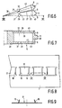
- a segment is limited by two radially directed surfaces 25, 27 of the wheel and adjoining walls 29 of axially directed holes 31 in the wheel.
- An elastically deformable bridge 33 is present between two successive cylindrical holes 31, as a result of which a segment 5 is displaceable in the tangential direction of the wheel with a force exerted on the relevant segment.
- FIGs 4 and 5 show a second embodiment of a segment of a wheel of the transmission system according to the invention, in which as far as possible reference numerals are used corresponding to Figures 1, 2 and 3.
- Each segment 5 has a strip twisted between the two radially directed surfaces 25, 27 about a radially directed shaft 35.
- a twisted part 37 in the form of a blade spring is obtained so that a segment 5 is displaceable with elastic deformation of the twisted part 37 in the tangential direction of the wheel.
- the twisted parts 37 may be welded to the running surface 9 and a core 38 of the relevant wheel.
- each wheel has two circular disks 39 and 41 of, for example, metal subdivided into sectors.
- a sector is partly limited by the radially directed surfaces 25, 27 of a wheel and the adjoining walls 29 of axially directed cylindrical holes 31 in the wheel.
- Sectors 43 of different disks 39, 41 are joined to form a segment 5 by means of a metal bridge 45 having a running surface 9 and a projection 11 and thus have a common running surface.
- the sectors 43 of the disks 39, 41 of a segment 5 are limited by the same radially directed surfaces 25, 27 of the wheel and walls 29 of identical axially directed cylindrical holes 31 of the two sectors.
- a segment can perform a movement in a plane directed tangentially with respect to the disks by means of the elastically deformable bridges 33 of the two disks 39 and 41.
- the disks 39 and 41 may be welded to the bridge 45 and the core 38.
- FIGS 8 and 9 show a part of the belt 7.
- This belt is made of a metal strip, in which the recesses 17 are formed by stamping and subsequent bending of the vanes 19.
- the motor drive according to the invention shown in Fig. 10 comprises an electric motor 49, an angular sensor 53 coupled to the motor shaft 51, a transmission system 2 according to the invention and a control unit 55.
- a path generator 61 supplies a digital signal, which is related to the desired path to be covered of a load 62, to a comparator 57.
- the signal supplied by the path generator 61 is compared with a position signal of the angular sensor 53 processed by a processor 63.
- the difference signal of the comparator 57 is supplied to a regulator 65, such a, for example, a PI or PID regulator, whose output signal is amplified in an amplifier 67 and is supplied in amplified form to the electric motor 49.
- the processor 63 processes the output signal of the angular sensor 53 also to a speed signal, which is supplied to a further comparator 59. Due to the unambiguous transmission ratio between the motor shaft and the outgoing shaft of the transmission system, there is a linear relation between the position indicated by the angle sensor 53 and the position of the load 63. Since the angle sensor is coupled to the motor shaft, the motor unit is more stable, from a control viewpoint, than if the angle sensor should be coupled to the outgoing shaft of the transmission system. The speed at which a new desired position of the load can be attained is high due to the high stability.
- the transmission system When transmitting high powers, it is possible to use several transmission systems arranged in parallel. Several wheels with parallel shaft may also be driven simultaneously by means of one or more transmission systems according to the invention.
- the wheels may be made entirely or in part of metal and/or synthetic material.
- the use of the transmission system according to the invention is otherwise not limited to embodiments in which use is made of angle sensors which are integrated in the motor.
- the transmission system In the case in which a position sensor is coupled to the load, the transmission system may be used in drives in which such a comparatively expensive sensor is not objectionable. In this manner, the production can be scaled up, which leads to a considerable saving in the overall cost of the transmission system.
Landscapes
- Engineering & Computer Science (AREA)
- General Engineering & Computer Science (AREA)
- Mechanical Engineering (AREA)
- Transmissions By Endless Flexible Members (AREA)
- Pulleys (AREA)
- Devices For Conveying Motion By Means Of Endless Flexible Members (AREA)
Applications Claiming Priority (2)
| Application Number | Priority Date | Filing Date | Title |
|---|---|---|---|
| NL8901662 | 1989-06-30 | ||
| NL8901662 | 1989-06-30 |
Publications (2)
| Publication Number | Publication Date |
|---|---|
| EP0405667A1 true EP0405667A1 (de) | 1991-01-02 |
| EP0405667B1 EP0405667B1 (de) | 1994-09-07 |
Family
ID=19854937
Family Applications (1)
| Application Number | Title | Priority Date | Filing Date |
|---|---|---|---|
| EP90201643A Expired - Lifetime EP0405667B1 (de) | 1989-06-30 | 1990-06-25 | Getriebe, Motorantrieb mit einem derartigen Getriebe sowie Rad für ein derartiges Getriebe oder einen derartigen Motorantrieb |
Country Status (4)
| Country | Link |
|---|---|
| US (1) | US5037359A (de) |
| EP (1) | EP0405667B1 (de) |
| JP (1) | JPH0341243A (de) |
| DE (1) | DE69012232T2 (de) |
Cited By (5)
| Publication number | Priority date | Publication date | Assignee | Title |
|---|---|---|---|---|
| FR2704289A1 (fr) * | 1993-04-21 | 1994-10-28 | Zeller Hans | Dispositif d'entraînement à bande et roue menante. |
| EP0677682A1 (de) * | 1994-04-13 | 1995-10-18 | Van Doorne's Transmissie B.V. | Fest übersetztes Getriebe |
| DE19536360A1 (de) * | 1995-09-29 | 1997-04-03 | Heidelberger Druckmasch Ag | Bogentransportvorrichtung |
| WO1999058879A1 (de) * | 1998-05-12 | 1999-11-18 | Hörmann KG Antriebstechnik | Führungs- oder an- bzw. abtriebsrad für ein zahngurtgetriebe sowie damit versehener zahngurtantrieb |
| WO2018223662A1 (zh) * | 2017-06-06 | 2018-12-13 | 江苏苏力机械股份有限公司 | 涂装行业智能化传动链驱动装置 |
Families Citing this family (4)
| Publication number | Priority date | Publication date | Assignee | Title |
|---|---|---|---|---|
| JP2520731Y2 (ja) * | 1991-07-10 | 1996-12-18 | 石川島播磨重工業株式会社 | 薄鋼板用調質圧延機の洗浄装置 |
| US5730870A (en) * | 1995-03-31 | 1998-03-24 | Randolph; Ovie L. | Oil change system and method |
| GB0717231D0 (en) * | 2007-09-05 | 2007-10-17 | Gough George T | Conveyors |
| DE102012104846A1 (de) * | 2012-06-05 | 2013-12-05 | Benchmark Drives GmbH & Co. KG | Zahnsegmentscheiben für Riemenantriebe |
Citations (3)
| Publication number | Priority date | Publication date | Assignee | Title |
|---|---|---|---|---|
| US3156126A (en) * | 1962-06-01 | 1964-11-10 | Sol A Levy Jr | Positive belt drives |
| US3173301A (en) * | 1962-07-12 | 1965-03-16 | Phillip A Miller | Power and force transmitting devices |
| GB2064061A (en) * | 1979-11-26 | 1981-06-10 | Conrad R A | Positive drive system |
Family Cites Families (2)
| Publication number | Priority date | Publication date | Assignee | Title |
|---|---|---|---|---|
| US3719098A (en) * | 1971-03-22 | 1973-03-06 | Olin Corp | Pulley belt assembly |
| US3851536A (en) * | 1973-02-16 | 1974-12-03 | Rockwell International Corp | Power transmission belt |
-
1990
- 1990-06-22 US US07/542,463 patent/US5037359A/en not_active Expired - Fee Related
- 1990-06-25 DE DE69012232T patent/DE69012232T2/de not_active Expired - Fee Related
- 1990-06-25 EP EP90201643A patent/EP0405667B1/de not_active Expired - Lifetime
- 1990-06-27 JP JP2166967A patent/JPH0341243A/ja active Pending
Patent Citations (3)
| Publication number | Priority date | Publication date | Assignee | Title |
|---|---|---|---|---|
| US3156126A (en) * | 1962-06-01 | 1964-11-10 | Sol A Levy Jr | Positive belt drives |
| US3173301A (en) * | 1962-07-12 | 1965-03-16 | Phillip A Miller | Power and force transmitting devices |
| GB2064061A (en) * | 1979-11-26 | 1981-06-10 | Conrad R A | Positive drive system |
Cited By (7)
| Publication number | Priority date | Publication date | Assignee | Title |
|---|---|---|---|---|
| FR2704289A1 (fr) * | 1993-04-21 | 1994-10-28 | Zeller Hans | Dispositif d'entraînement à bande et roue menante. |
| EP0677682A1 (de) * | 1994-04-13 | 1995-10-18 | Van Doorne's Transmissie B.V. | Fest übersetztes Getriebe |
| NL9400586A (nl) * | 1994-04-13 | 1995-11-01 | Doornes Transmissie Bv | Overbrenging met vaste overbrengingsverhouding. |
| US5662541A (en) * | 1994-04-13 | 1997-09-02 | Van Doorne's Transmissie B.V. | Transmission with fixed transmission ratio |
| DE19536360A1 (de) * | 1995-09-29 | 1997-04-03 | Heidelberger Druckmasch Ag | Bogentransportvorrichtung |
| WO1999058879A1 (de) * | 1998-05-12 | 1999-11-18 | Hörmann KG Antriebstechnik | Führungs- oder an- bzw. abtriebsrad für ein zahngurtgetriebe sowie damit versehener zahngurtantrieb |
| WO2018223662A1 (zh) * | 2017-06-06 | 2018-12-13 | 江苏苏力机械股份有限公司 | 涂装行业智能化传动链驱动装置 |
Also Published As
| Publication number | Publication date |
|---|---|
| DE69012232T2 (de) | 1995-04-06 |
| DE69012232D1 (de) | 1994-10-13 |
| EP0405667B1 (de) | 1994-09-07 |
| US5037359A (en) | 1991-08-06 |
| JPH0341243A (ja) | 1991-02-21 |
Similar Documents
| Publication | Publication Date | Title |
|---|---|---|
| EP0405667A1 (de) | Getriebe, Motorantrieb mit einem derartigen Getriebe sowie Rad für ein derartiges Getriebe oder einen derartigen Motorantrieb | |
| US4358166A (en) | Positioning devices | |
| GB2070258A (en) | Measuring torque | |
| JP2016211730A (ja) | 駆動装置および駆動装置を動作させるための方法 | |
| CA1052131A (en) | Pulley | |
| US5555776A (en) | Cam integrated with a rotation sensor | |
| US6206796B1 (en) | Power transmission mechanism using metal belts | |
| US4881828A (en) | Rolling contact device | |
| US6637118B2 (en) | Rotary encoder | |
| EP0114895A1 (de) | Kupplung eines stellmotors mit einem winkelaufnehmer | |
| JP4375720B2 (ja) | 樹脂歯車 | |
| EP3713058A1 (de) | Drehcodierer mit adaptiver installation | |
| US4881921A (en) | Flexible shaft coupling with coated grid | |
| US6513630B1 (en) | Double-wound band braking device | |
| EP0255961B1 (de) | Bimetallischer Indikator | |
| US3096631A (en) | Coupling | |
| EP0372575A2 (de) | Kodiereinrichtungsstruktur | |
| EP0035639B1 (de) | Nachgiebiges Drehteil und Reibradgetriebe | |
| JPH0914190A (ja) | 真空ポンプ | |
| CN217123240U (zh) | 一种传动机构 | |
| JPH08233071A (ja) | バックラッシュ除去型歯車 | |
| EP0369704A2 (de) | Friktionskupplung für Uhren | |
| JPS6042693B2 (ja) | 小型回転電機 | |
| JP3276455B2 (ja) | ダイアフラム継手 | |
| JPH0462977B2 (de) |
Legal Events
| Date | Code | Title | Description |
|---|---|---|---|
| PUAI | Public reference made under article 153(3) epc to a published international application that has entered the european phase |
Free format text: ORIGINAL CODE: 0009012 |
|
| AK | Designated contracting states |
Kind code of ref document: A1 Designated state(s): DE FR GB IT |
|
| 17P | Request for examination filed |
Effective date: 19910627 |
|
| 17Q | First examination report despatched |
Effective date: 19930421 |
|
| GRAA | (expected) grant |
Free format text: ORIGINAL CODE: 0009210 |
|
| AK | Designated contracting states |
Kind code of ref document: B1 Designated state(s): DE FR GB IT |
|
| REF | Corresponds to: |
Ref document number: 69012232 Country of ref document: DE Date of ref document: 19941013 |
|
| ITF | It: translation for a ep patent filed | ||
| ET | Fr: translation filed | ||
| ITPR | It: changes in ownership of a european patent |
Owner name: CAMBIO RAGIONE SOCIALE;PHILIPS ELECTRONICS N.V. |
|
| REG | Reference to a national code |
Ref country code: FR Ref legal event code: CD |
|
| PLBE | No opposition filed within time limit |
Free format text: ORIGINAL CODE: 0009261 |
|
| STAA | Information on the status of an ep patent application or granted ep patent |
Free format text: STATUS: NO OPPOSITION FILED WITHIN TIME LIMIT |
|
| 26N | No opposition filed | ||
| PGFP | Annual fee paid to national office [announced via postgrant information from national office to epo] |
Ref country code: GB Payment date: 19980601 Year of fee payment: 9 |
|
| PGFP | Annual fee paid to national office [announced via postgrant information from national office to epo] |
Ref country code: FR Payment date: 19980623 Year of fee payment: 9 |
|
| PGFP | Annual fee paid to national office [announced via postgrant information from national office to epo] |
Ref country code: DE Payment date: 19980824 Year of fee payment: 9 |
|
| REG | Reference to a national code |
Ref country code: FR Ref legal event code: CD |
|
| PG25 | Lapsed in a contracting state [announced via postgrant information from national office to epo] |
Ref country code: GB Free format text: LAPSE BECAUSE OF NON-PAYMENT OF DUE FEES Effective date: 19990625 |
|
| PG25 | Lapsed in a contracting state [announced via postgrant information from national office to epo] |
Ref country code: FR Free format text: THE PATENT HAS BEEN ANNULLED BY A DECISION OF A NATIONAL AUTHORITY Effective date: 19990630 |
|
| GBPC | Gb: european patent ceased through non-payment of renewal fee |
Effective date: 19990625 |
|
| PG25 | Lapsed in a contracting state [announced via postgrant information from national office to epo] |
Ref country code: DE Free format text: LAPSE BECAUSE OF NON-PAYMENT OF DUE FEES Effective date: 20000503 |
|
| REG | Reference to a national code |
Ref country code: FR Ref legal event code: ST |
|
| PG25 | Lapsed in a contracting state [announced via postgrant information from national office to epo] |
Ref country code: IT Free format text: LAPSE BECAUSE OF NON-PAYMENT OF DUE FEES Effective date: 20050625 |