EP0405639B1 - A ceramic gas burner for a hot blast stove, and bricks therefor - Google Patents
A ceramic gas burner for a hot blast stove, and bricks therefor Download PDFInfo
- Publication number
- EP0405639B1 EP0405639B1 EP90201549A EP90201549A EP0405639B1 EP 0405639 B1 EP0405639 B1 EP 0405639B1 EP 90201549 A EP90201549 A EP 90201549A EP 90201549 A EP90201549 A EP 90201549A EP 0405639 B1 EP0405639 B1 EP 0405639B1
- Authority
- EP
- European Patent Office
- Prior art keywords
- bricks
- principal
- shape
- brick
- gas burner
- Prior art date
- Legal status (The legal status is an assumption and is not a legal conclusion. Google has not performed a legal analysis and makes no representation as to the accuracy of the status listed.)
- Expired - Lifetime
Links
Images

Classifications
-
- F—MECHANICAL ENGINEERING; LIGHTING; HEATING; WEAPONS; BLASTING
- F23—COMBUSTION APPARATUS; COMBUSTION PROCESSES
- F23D—BURNERS
- F23D14/00—Burners for combustion of a gas, e.g. of a gas stored under pressure as a liquid
- F23D14/20—Non-premix gas burners, i.e. in which gaseous fuel is mixed with combustion air on arrival at the combustion zone
- F23D14/22—Non-premix gas burners, i.e. in which gaseous fuel is mixed with combustion air on arrival at the combustion zone with separate air and gas feed ducts, e.g. with ducts running parallel or crossing each other
-
- C—CHEMISTRY; METALLURGY
- C21—METALLURGY OF IRON
- C21B—MANUFACTURE OF IRON OR STEEL
- C21B9/00—Stoves for heating the blast in blast furnaces
-
- F—MECHANICAL ENGINEERING; LIGHTING; HEATING; WEAPONS; BLASTING
- F23—COMBUSTION APPARATUS; COMBUSTION PROCESSES
- F23D—BURNERS
- F23D2900/00—Special features of, or arrangements for burners using fluid fuels or solid fuels suspended in a carrier gas
- F23D2900/21—Burners specially adapted for a particular use
- F23D2900/21001—Burners specially adapted for a particular use for use in blast furnaces
Definitions
- the invention relates to a ceramic gas burner for a hot blast stove e.g. of a blast furnace, comprising a burner crown essentially composed of a plurality of shaped bricks which define terminal portions of air and gas ducts.
- a burner as described above is known for example from NL-A-8702037, corresponding to US-A-4 863 378. Because of the high thermal loading to which this kind of burner is exposed, its service life is generally much shorter than the service life of the hot blast stove in which it is installed. Repairing a burned-out burner is costly, and to a large extent this is related to the complex construction of the known burner. In fact the known burner is formed of over fifty different shaped bricks which each have to be placed precisely in their correct places. This means that the construction or reconstruction of such a burner is a job which must be carried out by highly qualified people. The complexity of the known burner also means that the construction or repair time lasts a considerable number of days, in general at least fifteen working days. Much of the costs of a repair are caused by the long downtime of the hot blast stove.
- EP-A-0398001 which specifies the application of especially shaped bricks provided on top of the burner-proper in order to improve the outflow of combustion gas and -air from the burner so as to improve its combustion-properties.
- EP-A-0398001 does not disclose any particulars about the shaped bricks that assembled constitute the burner-proper.
- An object of the invention is to provide a solution to the problems described above, so that at least the repair of a hot blast stove burner can be simpler and less expensive. Construction costs may also be reduced.
- the ceramic gas burner in accordance with the invention is given in claim 1.
- the burner crown is essentially composed of bricks of at most two principal shapes in which the first one of the principal shapes is essentially rectangular, with at least one of the dimensions of the top face of the brick being smaller than the bottom face of the same bricks.
- the brick of the second principal shape is essentially a trapezoid as seen in vertical section and has a bottom face of which the dimensions are essentially equal to the dimensions of the top face of the brick of the first principal shape.
- the brick of the first principal shape has generally parallel top and bottom faces and four side faces of which one is perpendicular to the bottom face over a part of the brick height.
- this brick is rectangular in plan view.
- the bricks of the second principal shape in this embodiment have top and bottom faces generally parallel to each other and four side faces of which three are generally perpendicular to the bottom face while the fourth is oblique so that the brick tapers upwardly.
- the brick of the first principal shape may also taper upwardly over part of its height.
- the brick of the first principal shape is preferably provided with at least one groove-shaped recess suitable for conduction combustion gas. Further a brick of the first principal shape is provided with at least one passage through it for conducting the combustion air, which is in line with a corresponding recess for conducting combustion air in the brick of the second principal shape that lies directly above the brick of the first principal shape.
- the dimensions of the passage for the combustion air may be adjusted in order to achieve a certain desired combustion characteristic of the burner.
- the known burner which is composed of may different shaped bricks, such an adjustment is not practical to carry out easily.
- the burner in accordance with the invention it is possible to achieve adjustment of the dimensions of the combustion air duct in a very simple way by minor adjustment of the dimensions of those two principal shapes of bricks which are relevant to the combustion air duct.
- each of the principal shapes of bricks has a secondary or subsidiary brick shape, consisting of identical bricks which are a fraction of the principal shape and are adapted for producing a composite brick by assembling with one or more further bricks of the same subsidiary shape, the dimensions of the composite brick being essentially equal to the dimensions of the brick of the principal shape from which the subsidiary shape is derived.
- Burners which have an uneven number of outlet openings for air may also be made in accordance with the invention with the aid of such subsidiary shape bricks.
- each of the bricks of at least one principal shape is provided with at least one groove in a side face, which groove in the assembled burner adjoins a side face of a neighbouring brick of the same principal shape.
- a ceramic cord may be placed in the groove or grooves which ensure that the bricks of the same principal shape are extremely well secured to each other.
- the bricks of the respective different principal shapes are located relative to each other by cooperating recesses and projections of the bricks.
- the invention further consists in a set of shaped bricks as described, for forming the crown of the ceramic burner in accordance with the invention.
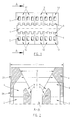
- combustion gas is passed through a central feeder duct 1 in the burner to the burner crown 6 and flows out at the upwardly widening outlet opening 3 into the combustion chamber of the hot blast stove.
- the outlet opening 3 has a rectangular slot shape.
- Two oblique bounding faces 10 (see Fig. 2) of the burner crown extend outward and upwards at an angle to the vertical, to define the outlet opening 3.
- the side walls 11 of the combustion chamber are partly shown in Fig. 2, but not shown in Fig. 1.
- combustion air feeder ducts 2 which discharge at second outlet openings 5 via angled passages 4. These air outlet openings 5 form two series, one on each side of first outlet opening 3.
- the top end of the burner is thus the crown 6 defining the terminal portions of the air and gas ducts.
- the ducts 1,2 are parallel and vertical.
- the passages 4 extend through the burner crown 6 built into the wall 11 of the combustion chamber.
- the crown is further bounded by the faces 10.
- the grooves 9 open out into the passages 4 at the outlet openings 5.
- the duct 8 forms a rectangular recess.
- opposite each of the air outlet openings 5 there lies a recess 8 formed by grooves 9.
- Combustion air coming out of the outlet openings 5 does not blow through the central gas flow, but flows towards it and along it.
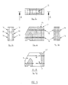
- the crown 6 defining the terminal duct parts 3,4,5 and 8 is composed of shaped ceramic bricks 12,13,14,15 arranged in two layers 20,21. Apart from their shapes, these refractory bricks are of a conventional nature for such a burner.
- the bricks are of only two principal shapes, each principal shape having one subsidiary type as described below. All the bricks of each shape are identical, with the brick of a subsidiary type being a fraction, in this case half, of a brick of the corresponding principal shape.
- Fig. 1 shows in top view the bricks 12,13 of the top layer 21. The boundary between the bricks is indicated by broken lines.
- Fig. 2 shows the different nature of the bottom layer 20 and top layer 21 of the burner crown 6 and here too the boundary faces are indicated by broken lines.
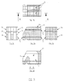
- the shaped bricks 14 (see Fig. 3) of the first of the two principal shapes form the bottom layer 20 of the burner crown.
- the subsidiary type 15 corresponding to the principal shape 14 is shown in Fig. 5.
- Fig. 4 shows the second principal shape of brick 12
- Fig. 6 shows a corresponding subsidiary type 13. These bricks 12,13 form the top layer 21 of the crown 6.
- the dimensions of the subsidiary shapes 15 and 13 are such that, when placed side by side, two examples of the same subsidiary shape have together dimensions which correspond with those of the corresponding principal shape 14 and 12 respectively. Since each brick 12,14 has two air outlet openings 5, with the subsidiary types 13,15 burners may be made with an uneven number of air outlet openings 5.
- Figs. 3 to 6 show the shapes of these bricks 12,13,14,15 in detail.
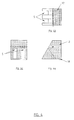
- the general outline of the brick 14 of Fig. 3 is cuboid, but one side face is oblique over part of the height, so that the top face is smaller in one dimension than the bottom face. Cut into this general outline are the grooves 9 and passages 4, each brick 14 having two grooves 9 and two passages 4. At the lower portion of the brick 14, the four side faces are perpendicular to the bottom face.
- the general outline of the brick 12 of Fig. 5 is trapezoidal, with three vertical side faces and one oblique side face.
- the dimensions of the bottom face of the brick 12 are almost exactly equal to those of the top face of the brick 14 on which the brick 12 sits.
- Grooves to form the outlet openings 5 of the passages 4 are cut into the general outline of the brick 12, and are aligned with the grooves 9 and passages 4 of the brick 14.
- the bricks 14 and 15 of the bottom layer 20 of the burner crown have small grooves 16 in the side walls 19 which adjoin neighbouring bricks in the layer 20.
- a ceramic cord may be placed in the through holes formed by the grooves 16 for the purpose of securing these bricks together (not shown in drawing).
- the bricks 14,15 are further provided with a recess 17 which cooperates with projections 18 of the shaped bricks 12,13 for the top layer 21, to locate the shaped bricks of the top layer 20 and the bottom layer 21 of the burner crown 6.
- Figs. 1 and 2 show that the arrangement of the bricks 12,13,14,15 is symmetrical about a vertical central plane extending longitudinally of the slot-shaped opening 3.
Landscapes
- Engineering & Computer Science (AREA)
- Chemical & Material Sciences (AREA)
- Manufacturing & Machinery (AREA)
- Materials Engineering (AREA)
- Metallurgy (AREA)
- Organic Chemistry (AREA)
- Combustion & Propulsion (AREA)
- Mechanical Engineering (AREA)
- General Engineering & Computer Science (AREA)
- Gas Burners (AREA)
- Pre-Mixing And Non-Premixing Gas Burner (AREA)
- Combustion Of Fluid Fuel (AREA)
Applications Claiming Priority (2)
| Application Number | Priority Date | Filing Date | Title |
|---|---|---|---|
| NL8901620A NL8901620A (nl) | 1989-06-27 | 1989-06-27 | Keramische brander en een daarvoor geschikte vormsteen. |
| NL8901620 | 1989-06-27 |
Publications (2)
| Publication Number | Publication Date |
|---|---|
| EP0405639A1 EP0405639A1 (en) | 1991-01-02 |
| EP0405639B1 true EP0405639B1 (en) | 1994-07-27 |
Family
ID=19854911
Family Applications (1)
| Application Number | Title | Priority Date | Filing Date |
|---|---|---|---|
| EP90201549A Expired - Lifetime EP0405639B1 (en) | 1989-06-27 | 1990-06-15 | A ceramic gas burner for a hot blast stove, and bricks therefor |
Country Status (12)
| Country | Link |
|---|---|
| US (1) | US5052922A (tr) |
| EP (1) | EP0405639B1 (tr) |
| CN (1) | CN1015926B (tr) |
| AU (1) | AU622378B2 (tr) |
| CA (1) | CA2019123C (tr) |
| DE (1) | DE69011005T2 (tr) |
| ES (1) | ES2057357T3 (tr) |
| MX (1) | MX173023B (tr) |
| NL (1) | NL8901620A (tr) |
| RU (1) | RU2076292C1 (tr) |
| TR (1) | TR25072A (tr) |
| UA (1) | UA26306A (tr) |
Families Citing this family (46)
| Publication number | Priority date | Publication date | Assignee | Title |
|---|---|---|---|---|
| US5228955A (en) * | 1992-05-22 | 1993-07-20 | Sun Coal Company | High strength coke oven wall having gas flues therein |
| US7998316B2 (en) | 2009-03-17 | 2011-08-16 | Suncoke Technology And Development Corp. | Flat push coke wet quenching apparatus and process |
| US9200225B2 (en) | 2010-08-03 | 2015-12-01 | Suncoke Technology And Development Llc. | Method and apparatus for compacting coal for a coal coking process |
| JP4955117B1 (ja) | 2011-03-15 | 2012-06-20 | 新日鉄エンジニアリング株式会社 | 炉頂燃焼式熱風炉 |
| JP4892107B1 (ja) * | 2011-03-23 | 2012-03-07 | 新日鉄エンジニアリング株式会社 | 炉頂燃焼式熱風炉 |
| CA2880539C (en) | 2012-07-31 | 2018-09-11 | Suncoke Technology And Development Llc | Methods for handling coal processing emissions and associated systems and devices |
| US9359554B2 (en) | 2012-08-17 | 2016-06-07 | Suncoke Technology And Development Llc | Automatic draft control system for coke plants |
| US9243186B2 (en) | 2012-08-17 | 2016-01-26 | Suncoke Technology And Development Llc. | Coke plant including exhaust gas sharing |
| US9249357B2 (en) | 2012-08-17 | 2016-02-02 | Suncoke Technology And Development Llc. | Method and apparatus for volatile matter sharing in stamp-charged coke ovens |
| US9169439B2 (en) | 2012-08-29 | 2015-10-27 | Suncoke Technology And Development Llc | Method and apparatus for testing coal coking properties |
| WO2014046701A1 (en) | 2012-09-21 | 2014-03-27 | Suncoke Technology And Development Llc. | Reduced output rate coke oven operation with gas sharing providing extended process cycle |
| US10016714B2 (en) | 2012-12-28 | 2018-07-10 | Suncoke Technology And Development Llc | Systems and methods for removing mercury from emissions |
| US10047295B2 (en) | 2012-12-28 | 2018-08-14 | Suncoke Technology And Development Llc | Non-perpendicular connections between coke oven uptakes and a hot common tunnel, and associated systems and methods |
| US10883051B2 (en) | 2012-12-28 | 2021-01-05 | Suncoke Technology And Development Llc | Methods and systems for improved coke quenching |
| US9476547B2 (en) | 2012-12-28 | 2016-10-25 | Suncoke Technology And Development Llc | Exhaust flow modifier, duct intersection incorporating the same, and methods therefor |
| US10760002B2 (en) | 2012-12-28 | 2020-09-01 | Suncoke Technology And Development Llc | Systems and methods for maintaining a hot car in a coke plant |
| US9273249B2 (en) | 2012-12-28 | 2016-03-01 | Suncoke Technology And Development Llc. | Systems and methods for controlling air distribution in a coke oven |
| US9238778B2 (en) | 2012-12-28 | 2016-01-19 | Suncoke Technology And Development Llc. | Systems and methods for improving quenched coke recovery |
| CN104884578B (zh) | 2012-12-28 | 2016-06-22 | 太阳焦炭科技和发展有限责任公司 | 通风竖管盖以及相关联的系统和方法 |
| US9193915B2 (en) | 2013-03-14 | 2015-11-24 | Suncoke Technology And Development Llc. | Horizontal heat recovery coke ovens having monolith crowns |
| US9273250B2 (en) | 2013-03-15 | 2016-03-01 | Suncoke Technology And Development Llc. | Methods and systems for improved quench tower design |
| CN105916965B (zh) | 2013-12-31 | 2021-02-23 | 太阳焦炭科技和发展有限责任公司 | 用于焦炉脱碳的方法及相关系统和装置 |
| EP3161106B1 (en) | 2014-06-30 | 2019-09-04 | Suncoke Technology and Development LLC | Horizontal heat recovery coke ovens having monolith crowns |
| AU2015308687A1 (en) | 2014-08-28 | 2017-03-16 | Suncoke Technology And Development Llc | Improved burn profiles for coke operations |
| CA2961207C (en) | 2014-09-15 | 2023-04-18 | Suncoke Technology And Development Llc | Coke ovens having monolith component construction |
| US10968395B2 (en) | 2014-12-31 | 2021-04-06 | Suncoke Technology And Development Llc | Multi-modal beds of coking material |
| US11060032B2 (en) | 2015-01-02 | 2021-07-13 | Suncoke Technology And Development Llc | Integrated coke plant automation and optimization using advanced control and optimization techniques |
| WO2016109854A1 (en) | 2015-01-02 | 2016-07-07 | Suncoke Technology And Development Llc | Integrated coke plant automation and optimization using advanced control and optimization techniques |
| CN105039622A (zh) * | 2015-08-27 | 2015-11-11 | 郑州安耐克实业有限公司 | 一种导流装置砖型 |
| CA3203921A1 (en) | 2015-12-28 | 2017-07-06 | Suncoke Technology And Development Llc | Method and system for dynamically charging a coke oven |
| RU2746968C2 (ru) | 2016-06-03 | 2021-04-22 | САНКОУК ТЕКНОЛОДЖИ ЭНД ДИВЕЛОПМЕНТ ЭлЭлСи. | Способы и системы для автоматического создания корректирующих действий в промышленном объекте |
| RU2768916C2 (ru) | 2017-05-23 | 2022-03-25 | САНКОУК ТЕКНОЛОДЖИ ЭНД ДИВЕЛОПМЕНТ ЭлЭлСи | Система и способ ремонта коксовой печи |
| CA3124811C (en) | 2018-12-28 | 2023-03-28 | Suncoke Technology And Development Llc | Heat recovery oven foundation |
| WO2020140079A1 (en) | 2018-12-28 | 2020-07-02 | Suncoke Technology And Development Llc | Decarbonizatign of coke ovens, and associated systems and methods |
| WO2020140086A1 (en) | 2018-12-28 | 2020-07-02 | Suncoke Technology And Development Llc | Particulate detection for industrial facilities, and associated systems and methods |
| US11008518B2 (en) | 2018-12-28 | 2021-05-18 | Suncoke Technology And Development Llc | Coke plant tunnel repair and flexible joints |
| BR112021012511B1 (pt) | 2018-12-28 | 2023-05-02 | Suncoke Technology And Development Llc | Sistema de forno de recuperação de calor carregado por mola e método |
| WO2020140074A1 (en) | 2018-12-28 | 2020-07-02 | Suncoke Technology And Development Llc | Improved oven uptakes |
| BR112021012412A2 (pt) | 2018-12-31 | 2021-09-08 | Suncoke Technology And Development Llc | Sistemas e métodos aprimorados para utilizar gás de combustão |
| US11395989B2 (en) | 2018-12-31 | 2022-07-26 | Suncoke Technology And Development Llc | Methods and systems for providing corrosion resistant surfaces in contaminant treatment systems |
| US12227699B2 (en) | 2019-12-26 | 2025-02-18 | Suncoke Technology And Development Llc | Oven health optimization systems and methods |
| EP4146767A4 (en) | 2020-05-03 | 2024-07-31 | Suncoke Technology and Development LLC | High-quality coke products |
| US11946108B2 (en) | 2021-11-04 | 2024-04-02 | Suncoke Technology And Development Llc | Foundry coke products and associated processing methods via cupolas |
| JP7595191B2 (ja) | 2021-11-04 | 2024-12-05 | サンコーク テクノロジー アンド ディベロップメント リミテッド ライアビリティ カンパニー | 鋳物用コークス生産物、及び関連システム、装置並びに方法 |
| WO2024098010A1 (en) | 2022-11-04 | 2024-05-10 | Suncoke Technology And Development Llc | Coal blends, foundry coke products, and associated systems, devices, and methods |
| WO2025111437A1 (en) | 2023-11-21 | 2025-05-30 | Suncoke Technology And Development Llc | Flat push hot car for foundry coke and associated systems and methods |
Citations (1)
| Publication number | Priority date | Publication date | Assignee | Title |
|---|---|---|---|---|
| EP0238001A2 (de) * | 1986-03-18 | 1987-09-23 | BASF Aktiengesellschaft | Copolymerisate des Isobutylens mit Nitro- und/oder Aminostyrol, deren Herstellung und Verwendung |
Family Cites Families (11)
| Publication number | Priority date | Publication date | Assignee | Title |
|---|---|---|---|---|
| DE1803985A1 (de) * | 1968-10-19 | 1971-03-04 | Didier Werke Ag | Waermegenerator,insbesondere Winderhitzer fuer Hochoefen |
| DE1803984B2 (de) * | 1968-10-19 | 1972-02-17 | Didier-Werke Ag, 6200 Wiesbaden | Keramische verbrennungseinrichtung fuer turmartige winder hitzer |
| DE2809521C2 (de) * | 1978-03-06 | 1986-03-06 | Didier-Werke Ag, 6200 Wiesbaden | Keramischer Brenner |
| US4378045A (en) * | 1978-10-19 | 1983-03-29 | Davy Inc. | Interlocking checker tile and supporting means for regenerative heating stoves |
| DE2903147C2 (de) * | 1979-01-27 | 1981-01-22 | Hermann Rappold & Co Gmbh, 5160 Dueren | Keramischer Brenner für Winderhitzer |
| DE3037950C2 (de) * | 1980-10-08 | 1985-09-12 | Dr. C. Otto & Co Gmbh, 4630 Bochum | Einrichtung zur Verbesserung des Strömungsverlaufes in den Überführungskanälen, die zwischen den Regeneratoren bzw. Rekuperatoren und den Verbrennungsräumen von technischen Gasfeuerungen, insbesondere von Koksöfen, angeordnet sind |
| US4353688A (en) * | 1981-03-12 | 1982-10-12 | United States Steel Corporation | Baffle structure for blast furnace stove |
| US4582485A (en) * | 1985-02-13 | 1986-04-15 | White Jr Herbert A | Blast furnace stove |
| JPS63282484A (ja) * | 1987-05-15 | 1988-11-18 | 株式会社ティーディーイー | 非鉄金属溶解炉 |
| NL8702036A (nl) * | 1987-08-31 | 1989-03-16 | Hoogovens Groep Bv | Keramische brander voor gas voor een brandschacht van een windverhitter van een hoogoven. |
| NL8702037A (nl) * | 1987-08-31 | 1989-03-16 | Hoogovens Groep Bv | Keramische brander voor een windverhitter. |
-
1989
- 1989-06-27 NL NL8901620A patent/NL8901620A/nl not_active Application Discontinuation
-
1990
- 1990-06-15 ES ES90201549T patent/ES2057357T3/es not_active Expired - Lifetime
- 1990-06-15 CA CA002019123A patent/CA2019123C/en not_active Expired - Fee Related
- 1990-06-15 DE DE69011005T patent/DE69011005T2/de not_active Expired - Fee Related
- 1990-06-15 EP EP90201549A patent/EP0405639B1/en not_active Expired - Lifetime
- 1990-06-18 US US07/539,590 patent/US5052922A/en not_active Expired - Lifetime
- 1990-06-25 AU AU57824/90A patent/AU622378B2/en not_active Ceased
- 1990-06-25 TR TR90/0576A patent/TR25072A/tr unknown
- 1990-06-26 MX MX021341A patent/MX173023B/es unknown
- 1990-06-26 RU SU904830337A patent/RU2076292C1/ru active
- 1990-06-27 CN CN90103314A patent/CN1015926B/zh not_active Expired
- 1990-09-26 UA UA4830337A patent/UA26306A/uk unknown
Patent Citations (1)
| Publication number | Priority date | Publication date | Assignee | Title |
|---|---|---|---|---|
| EP0238001A2 (de) * | 1986-03-18 | 1987-09-23 | BASF Aktiengesellschaft | Copolymerisate des Isobutylens mit Nitro- und/oder Aminostyrol, deren Herstellung und Verwendung |
Also Published As
| Publication number | Publication date |
|---|---|
| CA2019123A1 (en) | 1990-12-27 |
| MX173023B (es) | 1994-01-28 |
| CN1015926B (zh) | 1992-03-18 |
| TR25072A (tr) | 1992-11-01 |
| DE69011005T2 (de) | 1994-12-22 |
| US5052922A (en) | 1991-10-01 |
| AU5782490A (en) | 1991-01-03 |
| ES2057357T3 (es) | 1994-10-16 |
| NL8901620A (nl) | 1991-01-16 |
| EP0405639A1 (en) | 1991-01-02 |
| CA2019123C (en) | 1996-02-27 |
| AU622378B2 (en) | 1992-04-02 |
| UA26306A (uk) | 1999-08-30 |
| DE69011005D1 (de) | 1994-09-01 |
| CN1048447A (zh) | 1991-01-09 |
| RU2076292C1 (ru) | 1997-03-27 |
Similar Documents
| Publication | Publication Date | Title |
|---|---|---|
| EP0405639B1 (en) | A ceramic gas burner for a hot blast stove, and bricks therefor | |
| US3823875A (en) | Burner nozzle tip for pulverized coal and method for its production | |
| EP0832406B1 (en) | Brick for heat exchangers | |
| JP2002511126A (ja) | ガスタービンの冷却パネル | |
| MXPA97008622A (en) | Brick for ac changers | |
| US3891384A (en) | Stove burner | |
| EP0306072B1 (en) | Ceramic gas burner for a combustion chamber of a hot-blast stove | |
| EP0377233A1 (en) | Low NOx atmospheric gas burner | |
| US4150717A (en) | Interlocking checker tile | |
| US4569660A (en) | Furnace for firing ceramic materials, having a crown element incorporating thermal and/or mechanical stress resisting means | |
| US3529916A (en) | Radiant burner | |
| JPH0532645B2 (tr) | ||
| US2493470A (en) | Stove checker assembly | |
| KR20200000243U (ko) | 가스 버너 | |
| EP0949453B1 (en) | Burner plate | |
| US2185559A (en) | Checkerwork construction for regenerators | |
| AU738905B2 (en) | A gas hob | |
| JPS55118506A (en) | Pre-mixing type burner | |
| US3105541A (en) | Gas burner construction | |
| EP0137430B1 (en) | Chequer-brick for vertical cowpers and cowper chequerwork constructed from these chequer-bricks | |
| US4239600A (en) | Tall coke oven sole flue | |
| SU887907A1 (ru) | Решетка печи кип щего сло | |
| JPH0212423Y2 (tr) | ||
| US3130773A (en) | Air-cooled burner ring | |
| JP2571480Y2 (ja) | ガスバーナ |
Legal Events
| Date | Code | Title | Description |
|---|---|---|---|
| PUAI | Public reference made under article 153(3) epc to a published international application that has entered the european phase |
Free format text: ORIGINAL CODE: 0009012 |
|
| 17P | Request for examination filed |
Effective date: 19900618 |
|
| AK | Designated contracting states |
Kind code of ref document: A1 Designated state(s): BE DE ES FR GB IT LU NL |
|
| 17Q | First examination report despatched |
Effective date: 19930726 |
|
| GRAA | (expected) grant |
Free format text: ORIGINAL CODE: 0009210 |
|
| AK | Designated contracting states |
Kind code of ref document: B1 Designated state(s): BE DE ES FR GB IT LU NL |
|
| ITF | It: translation for a ep patent filed | ||
| ET | Fr: translation filed | ||
| REF | Corresponds to: |
Ref document number: 69011005 Country of ref document: DE Date of ref document: 19940901 |
|
| REG | Reference to a national code |
Ref country code: ES Ref legal event code: FG2A Ref document number: 2057357 Country of ref document: ES Kind code of ref document: T3 |
|
| PGFP | Annual fee paid to national office [announced via postgrant information from national office to epo] |
Ref country code: NL Payment date: 19950419 Year of fee payment: 6 |
|
| PGFP | Annual fee paid to national office [announced via postgrant information from national office to epo] |
Ref country code: FR Payment date: 19950510 Year of fee payment: 6 |
|
| PGFP | Annual fee paid to national office [announced via postgrant information from national office to epo] |
Ref country code: DE Payment date: 19950529 Year of fee payment: 6 |
|
| PGFP | Annual fee paid to national office [announced via postgrant information from national office to epo] |
Ref country code: BE Payment date: 19950530 Year of fee payment: 6 |
|
| PGFP | Annual fee paid to national office [announced via postgrant information from national office to epo] |
Ref country code: LU Payment date: 19950601 Year of fee payment: 6 |
|
| PLBE | No opposition filed within time limit |
Free format text: ORIGINAL CODE: 0009261 |
|
| STAA | Information on the status of an ep patent application or granted ep patent |
Free format text: STATUS: NO OPPOSITION FILED WITHIN TIME LIMIT |
|
| 26N | No opposition filed | ||
| PG25 | Lapsed in a contracting state [announced via postgrant information from national office to epo] |
Ref country code: LU Free format text: LAPSE BECAUSE OF NON-PAYMENT OF DUE FEES Effective date: 19960615 |
|
| PG25 | Lapsed in a contracting state [announced via postgrant information from national office to epo] |
Ref country code: BE Effective date: 19960630 |
|
| BERE | Be: lapsed |
Owner name: HOOGOVENS GROEP B.V. Effective date: 19960630 |
|
| PG25 | Lapsed in a contracting state [announced via postgrant information from national office to epo] |
Ref country code: NL Effective date: 19970101 |
|
| PG25 | Lapsed in a contracting state [announced via postgrant information from national office to epo] |
Ref country code: FR Effective date: 19970228 |
|
| PG25 | Lapsed in a contracting state [announced via postgrant information from national office to epo] |
Ref country code: DE Effective date: 19970301 |
|
| NLV4 | Nl: lapsed or anulled due to non-payment of the annual fee |
Effective date: 19970101 |
|
| REG | Reference to a national code |
Ref country code: FR Ref legal event code: ST |
|
| PGFP | Annual fee paid to national office [announced via postgrant information from national office to epo] |
Ref country code: GB Payment date: 20000523 Year of fee payment: 11 |
|
| PGFP | Annual fee paid to national office [announced via postgrant information from national office to epo] |
Ref country code: ES Payment date: 20000607 Year of fee payment: 11 |
|
| PG25 | Lapsed in a contracting state [announced via postgrant information from national office to epo] |
Ref country code: GB Free format text: LAPSE BECAUSE OF NON-PAYMENT OF DUE FEES Effective date: 20010615 |
|
| PG25 | Lapsed in a contracting state [announced via postgrant information from national office to epo] |
Ref country code: ES Free format text: LAPSE BECAUSE OF NON-PAYMENT OF DUE FEES Effective date: 20010616 |
|
| GBPC | Gb: european patent ceased through non-payment of renewal fee |
Effective date: 20010615 |
|
| REG | Reference to a national code |
Ref country code: ES Ref legal event code: FD2A Effective date: 20030203 |
|
| PG25 | Lapsed in a contracting state [announced via postgrant information from national office to epo] |
Ref country code: IT Free format text: LAPSE BECAUSE OF NON-PAYMENT OF DUE FEES;WARNING: LAPSES OF ITALIAN PATENTS WITH EFFECTIVE DATE BEFORE 2007 MAY HAVE OCCURRED AT ANY TIME BEFORE 2007. THE CORRECT EFFECTIVE DATE MAY BE DIFFERENT FROM THE ONE RECORDED. Effective date: 20050615 |