EP0405136B1 - Installation pour la mise à disposition d'eau chaude - Google Patents
Installation pour la mise à disposition d'eau chaude Download PDFInfo
- Publication number
- EP0405136B1 EP0405136B1 EP90109717A EP90109717A EP0405136B1 EP 0405136 B1 EP0405136 B1 EP 0405136B1 EP 90109717 A EP90109717 A EP 90109717A EP 90109717 A EP90109717 A EP 90109717A EP 0405136 B1 EP0405136 B1 EP 0405136B1
- Authority
- EP
- European Patent Office
- Prior art keywords
- water
- heating device
- water heating
- heater
- branch
- Prior art date
- Legal status (The legal status is an assumption and is not a legal conclusion. Google has not performed a legal analysis and makes no representation as to the accuracy of the status listed.)
- Expired - Lifetime
Links
- XLYOFNOQVPJJNP-UHFFFAOYSA-N water Substances O XLYOFNOQVPJJNP-UHFFFAOYSA-N 0.000 title claims abstract description 152
- 238000002360 preparation method Methods 0.000 title claims abstract 4
- 238000009434 installation Methods 0.000 title abstract description 5
- 238000010438 heat treatment Methods 0.000 claims abstract description 68
- 238000000605 extraction Methods 0.000 claims description 7
- 230000001419 dependent effect Effects 0.000 claims 1
- 229910052751 metal Inorganic materials 0.000 claims 1
- 238000010079 rubber tapping Methods 0.000 abstract description 31
- 238000001816 cooling Methods 0.000 abstract 1
- 239000000463 material Substances 0.000 description 4
- 238000001514 detection method Methods 0.000 description 2
- 238000005265 energy consumption Methods 0.000 description 2
- 238000009420 retrofitting Methods 0.000 description 2
- 230000002308 calcification Effects 0.000 description 1
- 238000000034 method Methods 0.000 description 1
Images


Classifications
-
- F—MECHANICAL ENGINEERING; LIGHTING; HEATING; WEAPONS; BLASTING
- F24—HEATING; RANGES; VENTILATING
- F24D—DOMESTIC- OR SPACE-HEATING SYSTEMS, e.g. CENTRAL HEATING SYSTEMS; DOMESTIC HOT-WATER SUPPLY SYSTEMS; ELEMENTS OR COMPONENTS THEREFOR
- F24D17/00—Domestic hot-water supply systems
-
- F—MECHANICAL ENGINEERING; LIGHTING; HEATING; WEAPONS; BLASTING
- F24—HEATING; RANGES; VENTILATING
- F24D—DOMESTIC- OR SPACE-HEATING SYSTEMS, e.g. CENTRAL HEATING SYSTEMS; DOMESTIC HOT-WATER SUPPLY SYSTEMS; ELEMENTS OR COMPONENTS THEREFOR
- F24D17/00—Domestic hot-water supply systems
- F24D17/0089—Additional heating means, e.g. electric heated buffer tanks or electric continuous flow heaters, located close to the consumer, e.g. directly before the water taps in bathrooms, in domestic hot water lines
-
- F—MECHANICAL ENGINEERING; LIGHTING; HEATING; WEAPONS; BLASTING
- F24—HEATING; RANGES; VENTILATING
- F24D—DOMESTIC- OR SPACE-HEATING SYSTEMS, e.g. CENTRAL HEATING SYSTEMS; DOMESTIC HOT-WATER SUPPLY SYSTEMS; ELEMENTS OR COMPONENTS THEREFOR
- F24D19/00—Details
- F24D19/10—Arrangement or mounting of control or safety devices
- F24D19/1006—Arrangement or mounting of control or safety devices for water heating systems
- F24D19/1051—Arrangement or mounting of control or safety devices for water heating systems for domestic hot water
Definitions
- the invention relates to a device for the immediate provision of hot water at a tapping point of a pipeline, which starts from a remote hot water supply device and which is provided at the tapping point with a switchable water heating device which can be switched off by means of a temperature detection device which responds to a predetermined temperature of the water arriving in the pipeline.
- JP-58-49836A In order to provide hot water immediately at a distant tapping point even at tapping points that are not connected to the hot water supply device via a return line, devices of the type mentioned at the outset are known (JP-58-49836A).
- This known device contains an additional water heating device in the area of the tapping point, which is constantly switched on and holds a certain amount of water at a sufficiently high temperature.
- This additional water heating device is only switched off when enough water has been removed that hot water has flowed from the removed hot water supply device to the extraction point and the temperature of this water exceeds a predetermined temperature. Since the temperature of the water in the area of a temperature sensor immediately in front of the tapping point drops over time if no water is drawn off, the additional water heating device is also switched on during this time, i.e. it is also switched on if no hot water is drawn for a long time. This leads to unnecessary energy consumption.
- the invention has for its object to provide a device of the type mentioned, which enables immediate hot water supply, without consuming energy unnecessarily.
- a switch responsive to the removal of water is provided for switching on the water heating device, and in that the water heating device is preceded by a thermo-hydraulic switch at which the wiring harness ends and from which a branch leads directly to the tapping point and a branch leads through the water heating device to the tapping point, and that the switch is controlled by the temperature detection device in such a way that, when the incoming water values are below the specified temperature, the branch with the water heating device and above the specified temperature The branch leading directly to the tapping point is open.
- the heat source of the water heating device is accordingly only used when water is drawn off and when the water present in the pipeline has cooled to an inadmissible extent. In the course of water withdrawal, however, hot water flows in from the distant or central hot water supply point, so that the additional heat source is then no longer needed and switches off automatically.
- the water heating device advantageously has a water heater.
- the instantaneous water heater is designed as a thermostatically and fluidically controlled electric instantaneous water heater, the heating elements of which can be switched on and off by a series connection of thermostat and differential pressure meter or flow meter (AND condition).
- the electric instantaneous water heater advantageously has a step circuit which enables the heating elements to be switched on and off in stages.
- the tap changer is optionally assigned to the flow meter or differential pressure meter and / or the thermostat.
- the water heating device is preceded by a thermo-hydraulic switch, at which the line ends and from which a branch leads directly to the tapping point and another branch leads via the water heating device to the tapping point.
- thermohydraulic switch opens the branch that goes directly to the tapping point if the water temperature at the entrance to the switch is sufficiently high. On the other hand, it automatically opens the branch to the water heating device to the extent that the water temperature at its entrance, that is to say at the end of the pipeline, is no longer sufficiently high, even without water being drawn off. At the same time, when the water temperature drops, it closes the branch going directly to the tapping point more or less quickly. If the tapping point is opened again, water flows through the water heating device until the thermo-hydraulic switch closes the branch leading to the water heating device again due to the rise in the inlet temperature.
- the water heating device can therefore contain uncomplicated, inexpensive heat sources. The only thing that matters is that warm water is available at the point of use. Complicated temperature controls are unnecessary for this.
- thermohydraulic switch is equipped with a control plug, the movement of which is brought about by a thermal element, preferably an expansion element or a bimetal element, depending on the water temperature at the end of the line.
- a thermal element preferably an expansion element or a bimetal element, depending on the water temperature at the end of the line.
- Expansion elements are proven, reliably working components, as are bimetal elements. Either wax or a wax-like material is used as the expansion material.
- a flow switch for switching a continuous-flow heater belonging to the water heating device is arranged in the branch leading to the water heating device.
- the heat output of the continuous-flow heater can be metered depending on the amount of water flowing per unit of time.
- the movement of the control plug is transferred to a switch which only switches on a water heater belonging to the water heating device when the control plug has simultaneously released the branch leading to the water heating device.
- the heating elements contained in the instantaneous water heater can of course be switched on and off in stages in order to adapt to the amount of water flowing through the instantaneous water heater per unit of time. This can also be done by the switch actuated by the movement of the control plug, which can be designed as a tap changer.
- the water heating device with flow heater and thermohydraulic switch forms a structural unit.
- Such a structural unit is easy to assemble anywhere. It is very suitable for retrofitting purposes. For retrofitting, it is only necessary, for example, to detach an existing tapping point from the end of the wiring harness, to couple the assembly to the end of the wiring harness and to connect the tapping point to the assembly. After the module is then connected to an electrical socket, it can go into operation if necessary.
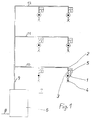
- a hot water main line 9 extends from the hot water supply device 6, which can contain, for example, a hot water reservoir.
- Branch lines 10, 11 and 12 branch off from the main line 9. From each branch line, two branch lines lead to the individual tapping points. The branch lines and the tapping points are each designed in the same way, so that in FIG. 1 only one branch line 3 and one tapping point 4 are provided with reference numbers.
- the connection point between secondary line 10 and branch line 3 is designed as a corner valve 2, which is shown in particular in FIG. 2. By turning the knurled wheel 13, the corner valve 2 can be closed and thereby the branch line 3 can be shut off from the secondary line 10.
- a switchable water heating device 1 with an electric instantaneous water heater 1 '. It is a thermostatically and fluidically controlled flow heater, the heating elements 14, 15, 16 of FIG. 2 can be switched on and off by a series connection of thermostat 5 and differential pressure meter or flow meter 17.
- the flow meter 17 is connected to a step switch 18, which enables the heating elements 14, 15, 16 to be switched on and off in stages.
- the thermostat 5 is located directly on the inflow side of the instantaneous water heater 1 '. It reacts to the water temperature in the branch line 3.
- the tapping point 4 is connected directly to the outlet nozzle 3 'of the instantaneous water heater 1'.
- the control current flow goes from phase R via the contact 19 of the thermostat 5, the line 33, the contacts 20, 21 and 22 of the tap changer 18 and the coils of the contactors 26, 27, 28 to the ground connections 29, 30, 31.
- the power flow goes from phases R, S, T via contacts 23, 24, 25 of contactors 26, 27, 28 and via heating elements 14, 15 and 16 to ground connection 32.
- a removal point 4 is opened after a long time, that is to say when the branch line 3 has cooled, the contact 19 of the thermostat 5 is closed, with the result that the contactors are actuated and the heating elements can be switched on.
- the contact 19 remains closed until the hot water inlet temperature at the inlet of the instantaneous water heater 1 'exceeds a predetermined limit value. Then the contact 19 opens again with the result that the contactors are switched off or can not be switched on again.
- the instantaneous heater 1 It depends on the strength of the flow or the level of the differential pressure whether the instantaneous heater 1 'puts a heating element 14, the two heating elements 14 and 15 or all three heating elements 14, 15, 16 into operation.
- the tap changer 22 When the flow is weak, only the contact 23 is included in the tap changer 22, and the heating element 14 heats the water flowing through the water heater 1. If the measured flow rate is somewhat higher, the tap changer 22 also closes the contact 21. This also puts the second heating element 15 into operation. With an even stronger flow, the tap changer 18 switches on all three contacts 20, 21 and 22. As a result, all three heating elements 14, 15 and 16 go into operation, so that the water heating is strongest.
- the intensity of the water heating determined additionally or exclusively by the thermostat 5, which could, for example, have three contacts, the heat-sensitive elements of which are matched to three different temperatures. Each contact would then switch a specific heating element, and thus the intensity of the heat development of the instantaneous water heater 1 ' would depend on which of the three temperature levels the water temperature is currently on the input side of the instantaneous water heater 1'.
- the heating elements of the instantaneous water heater 1 ' should only remain in operation until the hot water supply device 6 takes over the supply of hot water. After switching off, they remain switched off for as long as water is drawn off as long as the hot water inlet temperature of the instantaneous water heater 1 'does not fall below a certain limit value. This limit can of course be set on the thermostat. They remain switched off even during pausing, as long as the water temperature is still high enough. Only when the removal pause is so high that the temperature falls below the lower limit of the thermostat, the contact 19 is switched on again. The instantaneous water heater 1 'then takes over the immediate provision of sufficiently tempered water again during the next removal process.
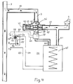
- the line 9, 10, 3 ends at a switchable water heating device 34.
- the tapping point 4 is connected directly to the water heating device 34.
- the water heating device 34 has a continuous-flow heater 35.
- the water heating device 34 is preceded by a thermohydraulic switch 36.
- the wiring harness 9, 10, 3 ends directly at this thermohydraulic switch 36.
- thermo-hydraulic switch 36 From the thermo-hydraulic switch 36, a branch 37 goes directly to the tapping point 4. Another branch 38 goes via a flow switch 39 to the inlet connection 40 of the instantaneous water heater 35. The outlet nozzle 41 of the continuous flow heater 35 is connected to the extraction point 4.
- thermohydraulic switch 36 is equipped with a control plug 42, the movement of which is brought about by a thermal element 43 as a function of the water temperature prevailing at the end of the pipeline 9, 10, 3.
- the thermal element 43 is preferably an expansion element.
- a shift rod 44 of the expansion element 43 is supported against a bridge 45 fixed to the housing.
- the housing 46 of the expansion element 43 is firmly connected to the control plug 42.
- a strong coil spring 47 is arranged so that it constantly tries to move the housing 46 and the control plug 42 as far as possible to the right until the control plug 42 closes the branch 37 and opens the branch 38 entirely, as shown in FIG. 3. This switching state of the control plug is reached at an impermissibly low water temperature at the end of branch line 3.
- the water heating device 34 forms a structural unit with the instantaneous heater 35, the thermohydraulic switch 36, the flow switch 39 and a relay 57, symbolized by a housing border 49 shown in broken lines.
- a line 52 leads from an external power connection mp to the coil 56 of the relay 57.
- a line 51 leads from the coil 56 to the flow switch 39. From an external power connection r, a line 50 also leads to the flow switch 39.
- a line 55 leads from an external power connection Mp to the instantaneous water heater 35. From an external power connection R, a line 53 leads to the switching bridge 58 of the relay 57. A line 54 leads from the switching contact 59 of the relay 57 to the instantaneous heater 35.
- the tapping point 4 is opened after a long pause in tapping, a water flow begins in the direction of the arrows, and the flow switch 39 is switched on by this flow.
- the coil 56 receives voltage, which then switches on the switching bridge 58, as shown in FIG. 3.
- the instantaneous heater 35 also receives voltage, for as long as the flow continues in a predetermined strength.
- the expansion material contained in the expansion element 43 expands, so that the switch plug 42 subsequently opens the branch 37 and closes the branch 38.
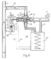
- the training according to FIG. 5 differs from the training according to FIGS. 3 and 4 by the following:
- the movement of the control plug 42 is transmitted through a switching rod 60 to the switching bridge 61 of a switch 62.
- the switch 62 switches on the flow heater 35 'belonging to the water heating device 34' via the relay 57 only when the control plug 42 has simultaneously released the branch 38 leading to the water heating device 34 'or its flow heater 35', as shown in FIG. 5.
- the relay 57 is equipped with a solenoid 63, which keeps the switching bridge 58 closed in the deenergized state, as shown in FIG. 5.
- a line 64 leads from the external electrical current connection r to the switching bridge 61 of the switch 62.
- a line 65 leads from the switching contact 66 of the switch 62 to the solenoid 63. From there, the line 52 leads to the external current connection mp.
- the new facility has the advantage that it does not cause additional energy costs when the tapping points are not used. Nevertheless, hot water is immediately available at the tapping points at any time. If a tapping point is used relatively frequently, no additional energy consumption can occur because the instantaneous water heater then remains switched off.
- the entire concept of the device according to the invention is such that it can be retrofitted practically anywhere at a reasonable cost.
- the repair effort in the device according to the invention in the event of faults is low.
- only one hot water supply point is shut down in the event of a fault.
- All other tapping points can remain fully functional.
- hot water can still be withdrawn to the usual extent from the tapping points.
- the facility is therefore designed redundantly, and disruption to the hot water supply is reduced to a minimum.
- thermo-hydraulic switch Calcification of the heating elements is reduced by the thermo-hydraulic switch.
- the volume flow reduced by the instantaneous water heater (dependence on temperature and quantity with a reasonable connected load) reaches its usual size due to the thermo-hydraulic switch, due to or supported by different pipe cross-sections.
Landscapes
- Engineering & Computer Science (AREA)
- General Engineering & Computer Science (AREA)
- Chemical & Material Sciences (AREA)
- Thermal Sciences (AREA)
- Combustion & Propulsion (AREA)
- Mechanical Engineering (AREA)
- Physics & Mathematics (AREA)
- Instantaneous Water Boilers, Portable Hot-Water Supply Apparatuses, And Control Of Portable Hot-Water Supply Apparatuses (AREA)
- Lubricants (AREA)
- Electrical Discharge Machining, Electrochemical Machining, And Combined Machining (AREA)
- Devices For Medical Bathing And Washing (AREA)
- Thermotherapy And Cooling Therapy Devices (AREA)
- Sorption Type Refrigeration Machines (AREA)
- Steam Or Hot-Water Central Heating Systems (AREA)
- Heat-Pump Type And Storage Water Heaters (AREA)
Claims (10)
- Installation pour la préparation immédiate d'eau à un point de prélèvement (4) d'un réseau de tuyauterie (9, 10, 3), lequel part d'une installation d'alimentation en eau à grande distance (6), et qui est pourvu, au niveau du point de prélèvement, d'un dispositif commutable d'échauffement de l'eau (1, 34, 34'), lequel peut être coupé à l'aide d'un détecteur de température qui réagit à une température prédéfinie de l'eau arrivant dans le réseau de tuyauteries, caractérisée en ce que, pour mettre en circuit le dispositif d'échauffement de l'eau, on prévoit un commutateur (17, 39) qui réagit au prélèvement de l'eau ; que le dispositif d'échauffement de l'eau est précédé d'un aiguillage thermo-hydraulique (36, 36') installé en amont, au niveau duquel se termine le réseau de tuyauteries (9, 10, 3), et duquel un embranchement (37) va directement au point de prélèvement (4) et un embranchement (38) va au point de prélèvement en passant par le dispositif d'échauffement de l'eau (34, 34') ; et que l'aiguillage est piloté par le détecteur de température (43), de telle sorte que, quand la température de l'eau qui arrive est inférieure à la température prédéfinie, c'est l'embranchement comportant le dispositif d'échauffement de l'eau qui est ouvert, tandis que c'est l'embranchement conduisant directement au point de prélèvement qui est ouvert quand la température est supérieure à la température prédéfinie.
- Installation selon la revendication 1, caractérisée en ce que, en tant que détecteur de température, un commutateur thermostatique (5, 43), qui réagit à la température de l'eau arrivant dans le réseau de tuyauteries (9, 10, 3), est installé en amont du dispositif d'échauffement de l'eau (1, 34, 34').
- Installation selon la revendication 1 ou 2, caractérisée en ce que le dispositif d'échauffement de l'eau (1, 34, 34' ) comporte un chauffe-eau instantané (1, 35, 35').
- Installation selon la revendication 3, caractérisée en ce que le chauffe-eau (1') est conçu comme un chauffe-eau instantané électrique à commande thermostatique et fluidique, dont les éléments chauffants (14, 15, 16) peuvent être mis en circuit ou hors circuit par un montage série d'un thermostat (5) et d'un manomètre à pression différentielle ou d'un débitmètre (17).
- Installation selon la revendication 4, caractérisée en ce que le chauffe-eau électrique instantané (1') comporte une connexion en cascade (18), qui permet des opérations étagées de mise en circuit et de mise hors circuit des éléments chauffants (14, 15, 16).
- Installation selon la revendication 5, caractérisée en ce que la connexion en cascade (18) est affectée au choix au manomètre à pression différentielle ou au débitmètre (17) et/ou au thermostat (5).
- Installation selon la revendication 1 ou l'une ou l'autre des revendications 2 à 6, caractérisée en ce que l'aiguillage thermo-hydraulique (36, 36') est muni d'un robinet de commande (42), dont le déplacement est provoqué en fonction de la température de l'eau régnant à l'extrémité du réseau de tuyauteries (9, 10, 3), par un élément thermique (43), de préférence un élément extensible ou un élément bimétallique.
- Installation selon la revendication 7, caractérisée en ce qu'un commutateur d'écoulement (39), destiné à mettre en circuit un chauffe-eau instantané (35) appartenant au dispositif d'échauffement de l'eau (34), est disposé dans l'embranchement (38) conduisant au dispositif d'échauffement de l'eau (34).
- Installation selon les revendications 7 ou 8, caractérisée en ce que le déplacement du robinet de commande (42) est transmis à un commutateur (62), qui ne met en circuit le chauffe-eau instantané (35') appartenant au dispositif d'échauffement de l'eau (34') que si le robinet de commande (42) a simultanément libéré l'embranchement (38) conduisant au dispositif d'échauffement de l'eau (34').
- Installation selon l'une des revendications 7 à 9, caractérisée en ce que le dispositif d'échauffement de l'eau (34) forme une seule et même structure (49) avec le chauffe-eau instantané (45) et l'aiguillage thermo-hydraulique (36), et éventuellement aussi avec le commutateur d'écoulement (39) et les dispositifs de commutation électrique (57) du chauffe-eau instantané (35).
Applications Claiming Priority (4)
| Application Number | Priority Date | Filing Date | Title |
|---|---|---|---|
| DE3921135 | 1989-06-28 | ||
| DE3921135 | 1989-06-28 | ||
| DE4011848A DE4011848A1 (de) | 1989-06-28 | 1990-04-12 | Einrichtung zur warmwasserbereitstellung |
| DE4011848 | 1990-04-12 |
Publications (3)
| Publication Number | Publication Date |
|---|---|
| EP0405136A2 EP0405136A2 (fr) | 1991-01-02 |
| EP0405136A3 EP0405136A3 (en) | 1991-05-15 |
| EP0405136B1 true EP0405136B1 (fr) | 1993-11-18 |
Family
ID=25882425
Family Applications (1)
| Application Number | Title | Priority Date | Filing Date |
|---|---|---|---|
| EP90109717A Expired - Lifetime EP0405136B1 (fr) | 1989-06-28 | 1990-05-22 | Installation pour la mise à disposition d'eau chaude |
Country Status (5)
| Country | Link |
|---|---|
| EP (1) | EP0405136B1 (fr) |
| AT (1) | ATE97478T1 (fr) |
| DE (2) | DE4011848A1 (fr) |
| DK (1) | DK0405136T3 (fr) |
| ES (1) | ES2046588T3 (fr) |
Cited By (1)
| Publication number | Priority date | Publication date | Assignee | Title |
|---|---|---|---|---|
| CN111156583A (zh) * | 2019-12-25 | 2020-05-15 | 哈尔滨新中新电子股份有限公司 | 一种可调节温度的校园洗浴用水供应系统 |
Families Citing this family (3)
| Publication number | Priority date | Publication date | Assignee | Title |
|---|---|---|---|---|
| GB9502673D0 (en) * | 1995-02-11 | 1995-03-29 | Benson Neville I | Combined shower |
| FR2824627A1 (fr) * | 2001-05-09 | 2002-11-15 | Sdecc | Dispositif de production d'eau chaude sanitaire a partir d'un miniballon a maintien electrique et d'une chaudiere mixte a gaz |
| GB2617341A (en) * | 2022-04-04 | 2023-10-11 | Chamberlain Toby | An ancillary water heating system |
Citations (2)
| Publication number | Priority date | Publication date | Assignee | Title |
|---|---|---|---|---|
| DE1753298A1 (de) * | 1967-02-09 | 1971-07-08 | Fonderie Soc Gen De | Haushalts-Warmwasserbereiter |
| EP0098450A2 (fr) * | 1982-07-02 | 1984-01-18 | Joh. Vaillant GmbH u. Co. | Source de chaleur chauffée par combustible |
Family Cites Families (2)
| Publication number | Priority date | Publication date | Assignee | Title |
|---|---|---|---|---|
| JPS59142348A (ja) * | 1983-02-02 | 1984-08-15 | Matsushita Electric Ind Co Ltd | 給湯装置 |
| JPS59153057A (ja) * | 1983-02-22 | 1984-08-31 | Matsushita Electric Ind Co Ltd | 給湯装置 |
-
1990
- 1990-04-12 DE DE4011848A patent/DE4011848A1/de not_active Withdrawn
- 1990-05-22 AT AT90109717T patent/ATE97478T1/de not_active IP Right Cessation
- 1990-05-22 DK DK90109717.0T patent/DK0405136T3/da active
- 1990-05-22 DE DE90109717T patent/DE59003508D1/de not_active Expired - Fee Related
- 1990-05-22 EP EP90109717A patent/EP0405136B1/fr not_active Expired - Lifetime
- 1990-05-22 ES ES199090109717T patent/ES2046588T3/es not_active Expired - Lifetime
Patent Citations (2)
| Publication number | Priority date | Publication date | Assignee | Title |
|---|---|---|---|---|
| DE1753298A1 (de) * | 1967-02-09 | 1971-07-08 | Fonderie Soc Gen De | Haushalts-Warmwasserbereiter |
| EP0098450A2 (fr) * | 1982-07-02 | 1984-01-18 | Joh. Vaillant GmbH u. Co. | Source de chaleur chauffée par combustible |
Cited By (2)
| Publication number | Priority date | Publication date | Assignee | Title |
|---|---|---|---|---|
| CN111156583A (zh) * | 2019-12-25 | 2020-05-15 | 哈尔滨新中新电子股份有限公司 | 一种可调节温度的校园洗浴用水供应系统 |
| CN111156583B (zh) * | 2019-12-25 | 2021-11-23 | 哈尔滨新中新电子股份有限公司 | 一种可调节温度的校园洗浴用水供应系统 |
Also Published As
| Publication number | Publication date |
|---|---|
| ATE97478T1 (de) | 1993-12-15 |
| DE59003508D1 (de) | 1993-12-23 |
| DE4011848A1 (de) | 1991-01-03 |
| EP0405136A3 (en) | 1991-05-15 |
| DK0405136T3 (da) | 1994-01-17 |
| EP0405136A2 (fr) | 1991-01-02 |
| ES2046588T3 (es) | 1994-02-01 |
Similar Documents
| Publication | Publication Date | Title |
|---|---|---|
| EP1170554B1 (fr) | Ensemble et procédé pour préparer de l'eau chaude sanitaire | |
| DE2524010B2 (de) | Steuerung für eine in Abhängigkeit von der Außentemperatur einstellbare Heizungsanlage | |
| EP0405136B1 (fr) | Installation pour la mise à disposition d'eau chaude | |
| DE102005035821B3 (de) | Thermische Solaranlage | |
| DE4135509C2 (de) | Verfahren zur Regelung einer in einem Umwälzkreislauf einer Heizungsanlage eingesetzten, drehzahlregelbaren Umwälzpumpe | |
| DE2753536C2 (de) | Steuerschaltung für eine Zentral- Heizungsanlage | |
| DE3629662A1 (de) | Steuerschaltung eines elektrischen durchlauferhitzers | |
| DE19517250A1 (de) | Gasheizgerät | |
| EP0931988A2 (fr) | Méthode et installation pour réduire le temps d'attente pour le tirage d'eau chaude | |
| DE2301832C3 (de) | Warmwasser-Zentralheizungssystem mit Vorlauf- und Brauchwasserthermostaten | |
| DE4308941C2 (de) | Anordnung zur Warmwasserbereitstellung für mit Gaswandgeräten beheizte Durchlaufspeicher | |
| DE19535891A1 (de) | Elektrische Heizzentrale | |
| DE1679365A1 (de) | Gasbeheizter Umlauf-Wassererhitzer | |
| EP0194637B1 (fr) | Circuit pour commander une source de chaleur chauffée par combustible et chargeant un réservoir à eau sanitaire | |
| DE2451544A1 (de) | Waermepumpe | |
| DE2150798C3 (de) | Schaltung zur Begrenzung der Heizleistung eines Heizungssystems während der Stoßbelastungszeit | |
| AT385345B (de) | Elektrischer durchlauferhitzer | |
| AT327443B (de) | Olbefeuerte warmwasser-umlaufheizung | |
| AT259815B (de) | Gasbeheizter Umlauf-Wassererhitzer | |
| DE3639286A1 (de) | Vorrichtung zur waermerueckgewinnung | |
| DE2256769B2 (de) | Warmwasser-Umlaufzentralheizung | |
| AT404183B (de) | Einrichtung zur erzeugung von warmwasser in objekten mit zentraler wärmeversorgung | |
| CH622337A5 (en) | Method and installation for heating rooms of a building | |
| DE1454513C (fr) | ||
| DE1254846B (de) | Thermostatisch geregelte Sammelheizungsanlage mit Umwaelzpumpe |
Legal Events
| Date | Code | Title | Description |
|---|---|---|---|
| PUAI | Public reference made under article 153(3) epc to a published international application that has entered the european phase |
Free format text: ORIGINAL CODE: 0009012 |
|
| AK | Designated contracting states |
Kind code of ref document: A2 Designated state(s): AT BE CH DE DK ES FR GB IT LI SE |
|
| PUAL | Search report despatched |
Free format text: ORIGINAL CODE: 0009013 |
|
| AK | Designated contracting states |
Kind code of ref document: A3 Designated state(s): AT BE CH DE DK ES FR GB IT LI SE |
|
| 17P | Request for examination filed |
Effective date: 19910917 |
|
| 17Q | First examination report despatched |
Effective date: 19920220 |
|
| RAP1 | Party data changed (applicant data changed or rights of an application transferred) |
Owner name: DEUTSCHE VORTEX GMBH |
|
| GRAA | (expected) grant |
Free format text: ORIGINAL CODE: 0009210 |
|
| ITF | It: translation for a ep patent filed |
Owner name: DE DOMINICIS & MAYER S. |
|
| AK | Designated contracting states |
Kind code of ref document: B1 Designated state(s): AT BE CH DE DK ES FR GB IT LI SE |
|
| REF | Corresponds to: |
Ref document number: 97478 Country of ref document: AT Date of ref document: 19931215 Kind code of ref document: T |
|
| REF | Corresponds to: |
Ref document number: 59003508 Country of ref document: DE Date of ref document: 19931223 |
|
| REG | Reference to a national code |
Ref country code: DK Ref legal event code: T3 |
|
| GBT | Gb: translation of ep patent filed (gb section 77(6)(a)/1977) |
Effective date: 19931220 |
|
| REG | Reference to a national code |
Ref country code: ES Ref legal event code: FG2A Ref document number: 2046588 Country of ref document: ES Kind code of ref document: T3 |
|
| ET | Fr: translation filed | ||
| PLBE | No opposition filed within time limit |
Free format text: ORIGINAL CODE: 0009261 |
|
| STAA | Information on the status of an ep patent application or granted ep patent |
Free format text: STATUS: NO OPPOSITION FILED WITHIN TIME LIMIT |
|
| 26N | No opposition filed | ||
| EAL | Se: european patent in force in sweden |
Ref document number: 90109717.0 |
|
| PGFP | Annual fee paid to national office [announced via postgrant information from national office to epo] |
Ref country code: GB Payment date: 20010511 Year of fee payment: 12 |
|
| PGFP | Annual fee paid to national office [announced via postgrant information from national office to epo] |
Ref country code: ES Payment date: 20010514 Year of fee payment: 12 |
|
| PGFP | Annual fee paid to national office [announced via postgrant information from national office to epo] |
Ref country code: SE Payment date: 20010516 Year of fee payment: 12 |
|
| PGFP | Annual fee paid to national office [announced via postgrant information from national office to epo] |
Ref country code: FR Payment date: 20010522 Year of fee payment: 12 Ref country code: AT Payment date: 20010522 Year of fee payment: 12 |
|
| PGFP | Annual fee paid to national office [announced via postgrant information from national office to epo] |
Ref country code: DK Payment date: 20010528 Year of fee payment: 12 |
|
| PGFP | Annual fee paid to national office [announced via postgrant information from national office to epo] |
Ref country code: DE Payment date: 20010530 Year of fee payment: 12 |
|
| PGFP | Annual fee paid to national office [announced via postgrant information from national office to epo] |
Ref country code: BE Payment date: 20010605 Year of fee payment: 12 |
|
| PGFP | Annual fee paid to national office [announced via postgrant information from national office to epo] |
Ref country code: CH Payment date: 20010727 Year of fee payment: 12 |
|
| REG | Reference to a national code |
Ref country code: GB Ref legal event code: IF02 |
|
| PG25 | Lapsed in a contracting state [announced via postgrant information from national office to epo] |
Ref country code: GB Free format text: LAPSE BECAUSE OF NON-PAYMENT OF DUE FEES Effective date: 20020522 Ref country code: AT Free format text: LAPSE BECAUSE OF NON-PAYMENT OF DUE FEES Effective date: 20020522 |
|
| PG25 | Lapsed in a contracting state [announced via postgrant information from national office to epo] |
Ref country code: SE Free format text: LAPSE BECAUSE OF NON-PAYMENT OF DUE FEES Effective date: 20020523 Ref country code: ES Free format text: LAPSE BECAUSE OF NON-PAYMENT OF DUE FEES Effective date: 20020523 |
|
| PG25 | Lapsed in a contracting state [announced via postgrant information from national office to epo] |
Ref country code: DK Free format text: LAPSE BECAUSE OF NON-PAYMENT OF DUE FEES Effective date: 20020531 Ref country code: BE Free format text: LAPSE BECAUSE OF NON-PAYMENT OF DUE FEES Effective date: 20020531 |
|
| PG25 | Lapsed in a contracting state [announced via postgrant information from national office to epo] |
Ref country code: LI Free format text: LAPSE BECAUSE OF THE APPLICANT RENOUNCES Effective date: 20020819 Ref country code: CH Free format text: LAPSE BECAUSE OF THE APPLICANT RENOUNCES Effective date: 20020819 |
|
| REG | Reference to a national code |
Ref country code: CH Ref legal event code: PL |
|
| PG25 | Lapsed in a contracting state [announced via postgrant information from national office to epo] |
Ref country code: DE Free format text: LAPSE BECAUSE OF NON-PAYMENT OF DUE FEES Effective date: 20021203 |
|
| REG | Reference to a national code |
Ref country code: DK Ref legal event code: EBP |
|
| EUG | Se: european patent has lapsed | ||
| GBPC | Gb: european patent ceased through non-payment of renewal fee |
Effective date: 20020522 |
|
| PG25 | Lapsed in a contracting state [announced via postgrant information from national office to epo] |
Ref country code: FR Free format text: LAPSE BECAUSE OF NON-PAYMENT OF DUE FEES Effective date: 20030131 |
|
| REG | Reference to a national code |
Ref country code: FR Ref legal event code: ST |
|
| REG | Reference to a national code |
Ref country code: ES Ref legal event code: FD2A Effective date: 20030611 |
|
| PG25 | Lapsed in a contracting state [announced via postgrant information from national office to epo] |
Ref country code: IT Free format text: LAPSE BECAUSE OF NON-PAYMENT OF DUE FEES;WARNING: LAPSES OF ITALIAN PATENTS WITH EFFECTIVE DATE BEFORE 2007 MAY HAVE OCCURRED AT ANY TIME BEFORE 2007. THE CORRECT EFFECTIVE DATE MAY BE DIFFERENT FROM THE ONE RECORDED. Effective date: 20050522 |