EP0405067A2 - Device for removing volatile contaminants from soil or similar - Google Patents
Device for removing volatile contaminants from soil or similar Download PDFInfo
- Publication number
- EP0405067A2 EP0405067A2 EP90106351A EP90106351A EP0405067A2 EP 0405067 A2 EP0405067 A2 EP 0405067A2 EP 90106351 A EP90106351 A EP 90106351A EP 90106351 A EP90106351 A EP 90106351A EP 0405067 A2 EP0405067 A2 EP 0405067A2
- Authority
- EP
- European Patent Office
- Prior art keywords
- container
- gas
- containers
- closed space
- gas supply
- Prior art date
- Legal status (The legal status is an assumption and is not a legal conclusion. Google has not performed a legal analysis and makes no representation as to the accuracy of the status listed.)
- Granted
Links
- 239000002689 soil Substances 0.000 title claims abstract description 17
- 239000000356 contaminant Substances 0.000 title description 3
- 239000000463 material Substances 0.000 claims abstract description 62
- 239000007789 gas Substances 0.000 claims abstract description 46
- 238000004140 cleaning Methods 0.000 claims abstract description 30
- 238000000034 method Methods 0.000 claims abstract description 23
- 239000000126 substance Substances 0.000 claims abstract description 11
- 239000011261 inert gas Substances 0.000 claims abstract description 9
- 238000009835 boiling Methods 0.000 claims abstract description 4
- 239000012855 volatile organic compound Substances 0.000 claims abstract 2
- 238000000605 extraction Methods 0.000 abstract description 4
- 229910000831 Steel Inorganic materials 0.000 abstract description 3
- 239000010959 steel Substances 0.000 abstract description 3
- 239000004927 clay Substances 0.000 abstract 1
- OKTJSMMVPCPJKN-UHFFFAOYSA-N Carbon Chemical compound [C] OKTJSMMVPCPJKN-UHFFFAOYSA-N 0.000 description 42
- 239000003344 environmental pollutant Substances 0.000 description 14
- 231100000719 pollutant Toxicity 0.000 description 14
- 238000009423 ventilation Methods 0.000 description 9
- XLYOFNOQVPJJNP-UHFFFAOYSA-N water Substances O XLYOFNOQVPJJNP-UHFFFAOYSA-N 0.000 description 7
- 238000010438 heat treatment Methods 0.000 description 5
- 238000003795 desorption Methods 0.000 description 4
- 238000011065 in-situ storage Methods 0.000 description 4
- 239000002585 base Substances 0.000 description 3
- 238000001179 sorption measurement Methods 0.000 description 3
- WYURNTSHIVDZCO-UHFFFAOYSA-N Tetrahydrofuran Chemical compound C1CCOC1 WYURNTSHIVDZCO-UHFFFAOYSA-N 0.000 description 2
- 230000001413 cellular effect Effects 0.000 description 2
- 238000011109 contamination Methods 0.000 description 2
- 238000001035 drying Methods 0.000 description 2
- 230000000694 effects Effects 0.000 description 2
- 230000002349 favourable effect Effects 0.000 description 2
- 238000011049 filling Methods 0.000 description 2
- 238000011068 loading method Methods 0.000 description 2
- 238000002156 mixing Methods 0.000 description 2
- 239000002245 particle Substances 0.000 description 2
- VGVRPFIJEJYOFN-UHFFFAOYSA-N 2,3,4,6-tetrachlorophenol Chemical class OC1=C(Cl)C=C(Cl)C(Cl)=C1Cl VGVRPFIJEJYOFN-UHFFFAOYSA-N 0.000 description 1
- BZHJMEDXRYGGRV-UHFFFAOYSA-N Vinyl chloride Chemical compound ClC=C BZHJMEDXRYGGRV-UHFFFAOYSA-N 0.000 description 1
- 238000010521 absorption reaction Methods 0.000 description 1
- 230000002411 adverse Effects 0.000 description 1
- 150000001298 alcohols Chemical class 0.000 description 1
- 150000001338 aliphatic hydrocarbons Chemical class 0.000 description 1
- 239000008346 aqueous phase Substances 0.000 description 1
- 150000004945 aromatic hydrocarbons Chemical class 0.000 description 1
- 239000003637 basic solution Substances 0.000 description 1
- 150000008280 chlorinated hydrocarbons Chemical class 0.000 description 1
- 150000008422 chlorobenzenes Chemical class 0.000 description 1
- 239000002734 clay mineral Substances 0.000 description 1
- 150000001875 compounds Chemical class 0.000 description 1
- 239000000470 constituent Substances 0.000 description 1
- 238000010276 construction Methods 0.000 description 1
- 230000029087 digestion Effects 0.000 description 1
- 230000010006 flight Effects 0.000 description 1
- 238000003958 fumigation Methods 0.000 description 1
- 150000008282 halocarbons Chemical class 0.000 description 1
- 239000012535 impurity Substances 0.000 description 1
- 239000007788 liquid Substances 0.000 description 1
- 239000000203 mixture Substances 0.000 description 1
- 239000012071 phase Substances 0.000 description 1
- 150000002989 phenols Chemical class 0.000 description 1
- 230000008929 regeneration Effects 0.000 description 1
- 238000011069 regeneration method Methods 0.000 description 1
- 230000000284 resting effect Effects 0.000 description 1
- 239000000243 solution Substances 0.000 description 1
- 239000002904 solvent Substances 0.000 description 1
- 238000002336 sorption--desorption measurement Methods 0.000 description 1
- 238000003860 storage Methods 0.000 description 1
- YLQBMQCUIZJEEH-UHFFFAOYSA-N tetrahydrofuran Natural products C=1C=COC=1 YLQBMQCUIZJEEH-UHFFFAOYSA-N 0.000 description 1
- 230000032258 transport Effects 0.000 description 1
- 230000003442 weekly effect Effects 0.000 description 1
Images


Classifications
-
- B—PERFORMING OPERATIONS; TRANSPORTING
- B09—DISPOSAL OF SOLID WASTE; RECLAMATION OF CONTAMINATED SOIL
- B09C—RECLAMATION OF CONTAMINATED SOIL
- B09C1/00—Reclamation of contaminated soil
- B09C1/005—Extraction of vapours or gases using vacuum or venting
-
- B—PERFORMING OPERATIONS; TRANSPORTING
- B09—DISPOSAL OF SOLID WASTE; RECLAMATION OF CONTAMINATED SOIL
- B09C—RECLAMATION OF CONTAMINATED SOIL
- B09C1/00—Reclamation of contaminated soil
- B09C1/06—Reclamation of contaminated soil thermally
Definitions
- the invention relates to a method for removing volatile pollutants from soil and comparable materials according to the preamble of claim 1 and devices for performing this method.
- Such a method is known per se as a so-called soil air extraction method.
- the contaminated soil is provided with soil air extraction wells in situ, through which air is constantly sucked off, which contains the volatile substances to be removed.
- soil air extraction extends over months or even years and can hardly be used with cohesive floors.
- the extracted air is cleaned by activated carbon filters that have already been tried and tested before they enter the free atmosphere.
- the contaminated soil and comparable materials are not treated in situ, but excavated for processing.
- This enables mechanical digestion with regard to an effective surface enlargement, which is particularly important for clayey / cohesive materials.
- the contaminated material is flowed through with quasi-inert gases, such as in particular air, the volatile pollutant constituents being desorbed from the surfaces of the substance particles and stripped from moist substance portions.
- quasi-inert gases such as in particular air
- the treatment of the material according to the invention makes it possible to distribute ventilation lines over the entire interior of the material to be processed.
- Treatment in a room that is closed to the atmosphere offers additional advantages.
- One of these is that the treatment gas can be circulated by switching on a cleaning process, thereby completely avoiding pollutant emissions into the atmosphere.
- By the circulation of the gas can also be heated with justifiable economic outlay, as a result of which the stripping effect within the soil material emanating from the gas can be increased considerably.
- the activated carbon system for gas cleaning can be designed as a double bed filter system so that an automatic desorption of the polluted activated carbon is possible. With a regenerable gas cleaning system, only the pollutants separated from the gas have to be disposed of.
- a device that can be used fundamentally to carry out the method according to the invention is the subject of claim 3.
- the configuration of the closed space as a portable container or container combination according to claim 4 is particularly useful and economical.
- Claim 14 which relates only to the method claims, describes a first alternative embodiment of the required closed space.
- the excavated material is then aerated in a type of screw conveyor with the cleaning gas, which is introduced into the inside of the screw and flows into the material to be processed through its surface in contact with the material to be processed.
- the advantage of this embodiment is the excellent ventilation due to the constant mixing of the soil material, which enables particularly short treatment times. While the treatment of the soil materials resting in containers in an enclosed space has to be carried out batchwise in weekly to monthly periods, the treatment with this screw conveyor solution can be carried out continuously. However, this may require connecting several screw conveyors in parallel or in series.
- the desorption rate can be increased considerably by heating or heating the cleaning gas.
- the flow of the heated gas leads to a gradual drying out of the moist materials. Under such dry conditions, the tendency to desorb is increased again significantly.
- the contaminated material is applied to an endless filter belt which is located in a closed container and is porous.
- the material enters and exits via cellular wheel locks.
- the material to be treated is transported through the apparatus on the filter belt and at the same time cleaned of the volatile contaminants by the treatment gas sucked through the material.
- the inert required for treatment Gas is in turn circulated through an adsorption / desorption system and expediently brought to a higher temperature before passing through the material and then cooled to below the dew point of the water conveyed in order not to reduce the active capacity of the activated carbon.
- the water is collected and disposed of separately. To clean the filter belt, it can be flushed with the inert gas or with water.
- energy can also be supplied by irradiation with infrared or other high-frequency beams in the wavelength range from 1 mm to 1 m.
- the closed space is formed by a bell 2 placed tightly on a base plate 1.
- the base plate and the bell can be made of any, but gas-tight material. In this respect, it is even possible to use appropriate tent material for the bell.
- the excavated soil to be cleaned of volatile pollutants is piled up inside the bell 2 as a pile 3 on the base plate 1.
- Perforated ventilation pipes 4 are spaced apart from one another within the pile 3 at a short distance from the base plate. Through these tubes 4 is a quasi-inert gas Air is blown through a line 5. The pollutant-laden air flowing through the pile is sucked out of the bell 2 through the line 6 and fed to an activated carbon gas cleaning system 7.
- the activated carbon cleaning device 7 consists of two containers filled with activated carbon, which are switched so that the other container is desorbed with superheated steam during the adsorption of the harmful gases on the activated carbon in one container.
- the cooled liquid mixture of water and pollutant is separated according to density and the aqueous phase is stripped of dissolved pollutants.
- the gas phase is fed back into the circuit and the water removed from the circuit and freed of pollutants is fed to a receiving water.
- the gas drawn off from the gas discharge line 6 and which is contaminated with the pollutants expediently passes through a compressor 8 (side channel compressor) and a cooler 25 before it reaches the gas cleaning system 7.
- the adsorption effect of the activated carbon is adversely affected by excessive temperatures.
- the clean gas is compressed again in a compressor 8 and, if necessary, fed back to the contaminated soil via line 5 via a heat exchanger 24.
- Fig. 2-4 show a practical design of a cleaning system.
- the closed space is a transpor Tabular box-shaped steel container 9.
- a container can have, for example, the standardized dimensions of 12.2 mx 2.4 mx 2.6 m.
- This container can be opened on one of its narrow end faces by means of gas-tight lockable doors 10.
- Commercially available mesh boxes 11 serve as porous containers for the material to be cleaned, which can have the size 1 mx 1 mx 1.2 m in the present specific example.
- These lattice boxes 11 can be stacked in pairs on top of each other on two pairs of rails 12 laid next to one another in the container 9 and introduced into the container.
- Each of the lattice boxes 11 is perforated with perforated ventilation pipes 13 laid at a distance from the closed bottom of the box.
- the perforation can be distributed unevenly over the circumference of the individual tube 13, the largest proportion of perforations generally pointing upwards in a geodetic manner.
- the container 9 is provided with air supply and discharge lines 14 and 15, respectively.
- the air which is drawn off via line 15 and contains pollutants is cleaned in an activated carbon cleaning device, which is not shown again here, and is recirculated to container 9 via line 14.
- the activated carbon cleaning device can in particular be such as is described in detail in the first exemplary embodiment.
- the loading of the mesh boxes 11 with contaminated material, the air exposure of the mesh boxes and their introduction into the container 9 is done as follows.
- the individual lattice boxes 11 which have already been filled with material or are still to be filled before the container opening is placed on rails temporarily laid in front of the container opening.
- the free open ends of the ventilation tubes 13 which protrude from the lattice boxes 11 are fast closures 16 interconnected with the help of individual pipe fittings 17.
- the grid boxes 11 can be inserted into the container 9 in pairs in the case of boxes stacked one above the other, or it is also possible for all the boxes outside the container to be connected to one another and then to be pushed together into the container 9.
- the connections of the pipe fittings to the air supply and discharge lines 14 and 15 can be made from the outside.
- the container of the size described above accommodates forty-four of the grid boxes 11 also dimensionally specified in the arrangement shown.
- the treatment of the material in the container 9 usually extends over periods of between days and a few weeks. Apart from the type of contamination present, the duration of the treatment also essentially depends on the volume flow of air that is sent through the container and its temperature. In the present example, a filling volume of the mesh boxes 11 of 1.2 cubic meters and a filling with a material processed to a specific weight of 1.3 t / cubic meter, the air flow rate is determined so that 1 cubic meter of material flows through about 20 cubic meters of air per hour becomes.
- the temperature of the air is set at about 50 degrees Celsius or more when it enters container 9, temperatures above 100 degrees Celsius being possible and advantageous. In order to avoid particle discharges from the material into the activated carbon filter, it is advisable to cover the mesh boxes 11 with non-woven filter materials.
- a particular advantage of the design of the required closed space as a steel container is that such a container easily transports it to the respective location of an impurity and carries it out there cleaning can be used.
- several containers can be used at the same time at one treatment location.
- all parts of the system, including the gas cleaning device are designed to be networkable in a modular manner.
- the process according to the invention can largely optimize the boundary conditions, which are different for different materials and are often still unknown in detail, for example by loosening and heating the material during ventilation.
- FIGS. 5 and 5.1 Another device for carrying out the method according to the invention are the screw conveyors 18 shown in FIGS. 5 and 5.1.
- the treatment gas is in turn circulated through them, a countercurrent or cocurrent to the conveying direction of the material to be processed being possible.
- the special feature of this embodiment is that the screws 26 are hollow and have a porous surface connected to the material to be treated and connected to the cavity. The porosity can be generated by a large number of individual openings 27.
- Several of the screw conveyors 18 are expediently connected in series in order in this way to obtain a cleaning process with material that can be continuously carried out and to be able to manage with extremely short treatment times.
- the material is fed into the first screw conveyor 18 via a feed hopper 19 and drawn off from the third and thus last screw conveyor in the example shown via a cellular wheel sluice 20.
- the short treatment times are here due to the excellent mixing of the treatment gas emerging directly from the screws 26 with that conveyed through the screw flights Material reached.
- This procedural and apparatus-favorable procedure is combined with a special heating of the desorption air to around 40 to 220 degrees Celsius.
- a very effective and fast-working thermal desorption is initiated by an appropriate drying process of the contaminated material, which ensures particularly effective cleaning in strongly cohesive soils.
- the hot polluted air must be cooled to approx. 30 degrees Celsius by a separator in order to ensure sufficient absorption of the remaining gaseous pollutants in the downstream activated carbon system.
- This process variant can be operated continuously.
- FIG. 6 A further continuously operable device is shown in FIG. 6.
- the material to be treated is placed on an endless filter belt 22 located in a closed container 21.
- the filter belt 22 is porous.
- the material to be treated is transported on the filter belt 22 through the container 21 and drawn off from the container in a decontaminated manner.
- the inert gas required for the treatment is in turn circulated, the regeneration of the gas taking place in the cleaning system 7 already described above.
- the material to be treated is flowed through by the circulated inert gas for taking up the contaminants through the porous filter belt.
- the filter belt, together with the material to be treated passes through a closed suction device 23 acted upon by the inert gas.
- the inert gas Before entering the suction device 23, the inert gas is heated in a heating device 24 while it is being heated Entry into the activated carbon cleaning system 7 in one Heat exchanger 25 is cooled to a temperature conducive to the activated carbon filter system.
- the filter belt 22 can be adapted in terms of its circulation speed to the type and degree of contamination of the material to be processed in each case.
- the belt In order to maintain the porosity of the filter belt 22 continuously, the belt can pass through a cleaning system outside the suction device 23, in which it is rinsed with water or blown with compressed air, for example.
- Substances which can be eliminated by the process according to the invention and the facilities proposed for carrying it out can be, for example: aliphatic and aromatic hydrocarbons, halogenated hydrocarbons, in particular chlorinated hydrocarbons, chlorofluorocarbons and low-boiling solvents such as tetrahydrofuran, cyclohexanane etc. and chlorobenzenes, alcohols, Phenols and chlorophenols, etc. Overall, however, all low-boiling and / or steam-volatile compounds can be removed.
- the method according to the invention is basically based on the principle of desorbing or thermally desorbing the removable volatile substances by targeted fumigation on the one hand and suction on the other hand and then adsorbing the desorbed substances on an adsorber such as activated carbon and thereby avoiding the gas Pollution of the atmosphere as constant as possible.
Landscapes
- Life Sciences & Earth Sciences (AREA)
- Soil Sciences (AREA)
- Engineering & Computer Science (AREA)
- Environmental & Geological Engineering (AREA)
- Physics & Mathematics (AREA)
- Thermal Sciences (AREA)
- Processing Of Solid Wastes (AREA)
- Treating Waste Gases (AREA)
- Fire-Extinguishing Compositions (AREA)
Abstract
Ein Verfahren zur Entfernung flüchtiger Stoffe, insbesondere niedrigsiedender und/oder wasserdampfflüchtiger organischer Verbindungen aus Erdböden und vergleichbaren Materialien, insbesondere solcher, die mit hohen Anteilen in bindiger/toniger Form vorliegen, durch Absaugen und Reinigen des abgesaugten mit den zu entfernenden Stoffen kontaminierten Gases soll wirksamer und wirtschaftlicher ausgestaltet werden.A method for removing volatile substances, in particular low-boiling and / or steam-volatile organic compounds from soil and comparable materials, in particular those which are present in high proportions in cohesive / clay form, by suction extraction and cleaning of the extracted gas contaminated with the substances to be removed is said to be more effective and be made more economical.
Zu diesem Zweck wird das zu reinigende Material in einen geschlossenen Raum eingebracht, in dem ein quasi inertes Gas in das Innere dieses Materials eingeführt wird, das nach Durchströmen des Materials aus dem geschlossenen Raum wieder abgezogen, gereinigt und diesem im Kreislauf bis zur Erzielung des gewünschten Reinheitsgrades des aufzübereitenden Materials wieder zugeführt wird.For this purpose, the material to be cleaned is introduced into a closed space, in which a quasi-inert gas is introduced into the interior of this material, which, after flowing through the material, is drawn off again from the closed space, cleaned and circulated until the desired is achieved Degree of purity of the material to be processed is fed back.
Als geschlossener Raum ist als eine Version ein transportabler Stahl-Container (9) einsetzbar, in welchem das kontaminierte Bodenmaterial in herausnehmbaren Gitterboxen (11) belüftet wird.A version of a portable steel container (9) can be used as a closed space, in which the contaminated floor material is ventilated in removable mesh boxes (11).
Bei weiteren Versionen erfolgt die Behandlung des Materials kontinuierlich in gasdurchfluteten Schneckenförderern oder Bandfiltern.
Description
Die Erfindung betrifft ein Verfahren zur Entfernung flüchtiger Schadstoffe aus Erdböden und vergleichbaren Materialien nach dem Oberbegriff des Patentanspruchs 1 sowie Einrichtungen zur Durchführung dieses Verfahrens.The invention relates to a method for removing volatile pollutants from soil and comparable materials according to the preamble of
Ein solches Verfahren ist als sogenanntes Bodenluftabsaugungsverfahren an sich bekannt. Dabei wird das kontaminierte Erdreich in situ mit Bodenluftabsaugbrunnen versehen, durch die beständig Luft abgesaugt wird, in der sich die zu entfernenden flüchtigen Stoffe befinden. Eine solche Bodenluftabsaugung erstreckt sich im Hinblick auf einen zufriedenstellenden Reinigungserfolg über Monate oder gar Jahre und kann bei bindigen Böden kaum eingesetzt werden. Die abgesaugte Luft wird bei hohen Schadstoffgehalten vor Eintritt in die freie Atmosphäre durch bereits praxiserprobte Aktivkohlefilter gereinigt.Such a method is known per se as a so-called soil air extraction method. The contaminated soil is provided with soil air extraction wells in situ, through which air is constantly sucked off, which contains the volatile substances to be removed. With a view to satisfactory cleaning success, such soil air extraction extends over months or even years and can hardly be used with cohesive floors. In the event of high pollutant contents, the extracted air is cleaned by activated carbon filters that have already been tried and tested before they enter the free atmosphere.
Hierbei werden in der Regel entweder Einwegaktivkohlefilter oder selbständig regenerierbare Aktivkohleanlagen eingesetzt.As a rule, either disposable activated carbon filters or independently regenerable activated carbon systems are used.
Die Nachteile dieser in situ arbeitenden Verfahren sind somit in den teilweise extrem langen Behandlungszeiten und in der Anwendungseinschschränkung bei bindigen Böden zu sehen.The disadvantages of these methods, which work in situ, can be seen in the sometimes extremely long treatment times and in the application restrictions for cohesive soils.
Hier ein wirksameres und wirtschaftlich einsetzbares Verfahren mit entsprechenden Einrichtungen zu schaffen, ist die Aufgabe der vorliegenden Erfindung.It is the object of the present invention to create a more efficient and economically usable method with appropriate facilities.
Die grundsätzliche Lösung dieser Aufgabe besteht erfindungsgemäß in einem Verfahren nach dem kennzeichnenden Teil des Patentanspruchs 1.The basic solution to this problem consists according to the invention in a method according to the characterizing part of
Hiernach werden der kontaminierte Erdboden und vergleichbare Materialien nicht in situ behandelt, sondern zur Aufbereitung ausgehoben. Dadurch ist ein mechanischer Aufschluß im Hinblick auf eine wirksame Oberflächenvergrößerung möglich, der insbesondere für tonige/bindige Materialien von großer Wichtigkeit ist. Das belastete Material wird mit quasi inerten Gasen, wie insbesondere Luft, durchströmt, wobei die flüchtigen Schadstoffbestandteile von den Oberflächen der Stoffpartikel desorbiert und aus feuchten Stoffanteilen gestript werden. Auf diese Weise lassen sich die Behandlungszeiten ganz erheblich verringern und zwar in beonders günstigen Fällen beispielsweise auf bis zu zwei Wochen. Selbst bei sehr ungünstigen Voraussetzungen, wie sehr hoher Schadstoffbelegung in stark tonmineralhaltigen Materialien ist im Regelfalle mit einer Behandlungszeit kaum über 3 Monaten zu rechnen.According to this, the contaminated soil and comparable materials are not treated in situ, but excavated for processing. This enables mechanical digestion with regard to an effective surface enlargement, which is particularly important for clayey / cohesive materials. The contaminated material is flowed through with quasi-inert gases, such as in particular air, the volatile pollutant constituents being desorbed from the surfaces of the substance particles and stripped from moist substance portions. In this way, the treatment times can be reduced considerably, and in particularly favorable cases, for example up to two weeks. Even in the case of very unfavorable conditions, such as very high levels of pollutants in materials that contain a lot of clay minerals, treatment times can hardly be expected to exceed 3 months.
Durch die erfindungsgemäße Behandlung des Materials ist es möglich, Belüftungsleitungen über das gesamte Innere des aufzübereitenden Materials zu verteilen. Die Behandlung in einem zur Atmosphäre abgeschlossenen Raum bietet zusätzlich weitere Vorteile. Einer davon besteht darin, daß das Behandlungsgas im Kreislauf unter Einschalten eines Reinigungsprozesses geführt werden kann, wodurch Schadstoffemissionen in die Atmosphäre ganz vermieden werden. Durch die Kreislaufführung des Gases kann dieses auch mit vertretbarem wirtschaftlichen Aufwand erwärmt werden, wodurch der von dem Gas ausgehende Stripeffekt innerhalb des Bodenmaterials erheblich gesteigert werden kann. Die Aktivkohleanlage zur Gasreinigung kann als Doppelbett-Filteranlage so ausgebildet sein, daß eine selbsttätige Desorption der schadstoffbelegten Aktivkohle möglich ist. Bei einer regenerierbaren Gasreinigungsanlage müssen nur noch die aus dem Gas abgetrennten Schadstoffe entsorgt werden.The treatment of the material according to the invention makes it possible to distribute ventilation lines over the entire interior of the material to be processed. Treatment in a room that is closed to the atmosphere offers additional advantages. One of these is that the treatment gas can be circulated by switching on a cleaning process, thereby completely avoiding pollutant emissions into the atmosphere. By the circulation of the gas can also be heated with justifiable economic outlay, as a result of which the stripping effect within the soil material emanating from the gas can be increased considerably. The activated carbon system for gas cleaning can be designed as a double bed filter system so that an automatic desorption of the polluted activated carbon is possible. With a regenerable gas cleaning system, only the pollutants separated from the gas have to be disposed of.
Eine grundsätzlich zur Durchführung des erfindungsgemäßen Verfahrens einsetzbare Einrichtung ist Gegenstand des Anspruchs 3.A device that can be used fundamentally to carry out the method according to the invention is the subject of claim 3.
Besonders zweckmäßig und wirtschaftlich einsetzbar ist die Ausgestaltung des geschlossenen Raumes als transportabler Behälter oder Behälterkombination nach Anspruch 4.The configuration of the closed space as a portable container or container combination according to claim 4 is particularly useful and economical.
Es kann auch ein ehemaliger, aufgelassener Eisenbahntunnel, sofern er gasdicht ist, die Funktion des geschlossenen Raumes übernehmen.A former, abandoned railroad tunnel, if it is gas-tight, can also take over the function of the closed space.
Die weiteren letztlich jeweils bis zum Anspruch 3 rückbezogenen Ansprüche 5 bis 13 beinhalten im wesentlichen auf die Containerbauweise besonders abgestimmte Ausgestaltungen der die kontaminierten Materialien zur Belüftung aufnehmenden Einzelbehälter in bezug auf deren Gasanschlüsse sowie deren Lagerung innerhalb des Containers mit den damit verbundenen Beschickungs- und Entleerungsmöglichkeiten. Weitere Einzelheiten hierzu werden im Zusammenhang mit der Beschreibung von Ausführungsbeispielen noch näher erläutert werden.The further claims 5 to 13, which in the end refer back to claim 3, essentially contain configurations of the individual containers receiving the contaminated materials for ventilation with respect to their gas connections and their storage within the container, with the associated loading and emptying options, which are particularly adapted to the container construction. Further details on this will be explained in more detail in connection with the description of exemplary embodiments.
Der lediglich auf die Verfahrensansprüche rückbezogene Anspruch 14 beschreibt eine erste alternative Ausführungsform des erforderlichen geschlossenen Raumes. Danach wird das ausgehobene Material in einer Art Schneckenförderer mit dem Reinigungsgas belüftet, das in das Innere der Schnecke eingeleitet und durch deren mit dem aufzübereitenden Material in Berührung stehenden Oberfläche hindurch in das aufzuarbeitende Material einströmt. Der Vorteil dieser Ausführungsform besteht in der aufgrund der ständigen Durchmischung des Bodenmaterials hervorragenden Belüftung, die besonders kurze Behandlungszeiten ermöglicht. Während die Behandlung der in Behältern in einem geschlossenen Raum ruhenden Bodenmaterialien chargenweise in Wochen- bis zu Monatsperioden erfolgen muß, kann die Behandlung bei dieser Schneckenförderer-Lösung kontinuierlich erfolgen. Dazu kann es allerdings erforderlich sein, mehrere Schneckenförderer parallel oder hintereinander zu schalten. Durch Erwärmen bzw. Aufheizen des Reinigungsgases kann die Desorptionsrate erheblich gesteigert werden. Darüber hinaus führt das Durchströmen des aufgeheizten Gases zu einer allmählichen Austrocknung der feuchten Materialien. Unter solchen trokkenen Bedingungen werden die Desorptionsneigungen noch einmal wesentlich erhöht.
Bei einer zweiten kontinuierlich betreibbaren Einrichtung nach den Ansprüchen 15 und 16 wird das kontaminierte Material auf ein in einem geschlossenen Behälter befindliches Endlos-Filterband aufgegeben, das porös ist. Um den Behälter zur Atmosphäre hin abzuschließen, erfolgen Eintritt und Austritt des Materials über Zellenradschleusen. Auf dem Filterband wird das zu behandelnde Material durch die Apparatur transportiert und gleichzeitig durch das durch das Material gesaugte Bahandlungsgas von den flüchtigen Kontaminanten gereinigt. Das zur Behandlung erforderliche inerte Gas wird wiederum über eine Adsorptions-/Desorptions-Anlage im Kreis geführt und dabei zweckmäßigerweise vor Passieren des Materials auf eine höhere Temperatur gebracht und danach, um die Wirkkapazität der Aktivkohle nicht zu vermindern, unter den Taupunkt des mitgeförderten Wassers gekühlt. Das Wasser wird gesammelt und separat entsorgt. Zur Abreinigung des Filterbandes kann dieses mit dem inerten Gas oder mit Wasser gegengespült werden.In a second continuously operable device according to
Weitere Möglichkeiten zur Entfernung flüchtiger Schadstoffe aus Erdböden oder vergleichbaren Materialien in Verbindung mit einer Aktivkohle-Gasreinigungsanlage sind Apparaturen in der Art von Etagenöfen oder Tellertrocknern.Other options for removing volatile pollutants from soil or comparable materials in connection with an activated carbon gas cleaning system are devices such as deck ovens or plate dryers.
Bei den kontinuierlich betriebenen Anlagen kann eine Energiezuführung auch durch Bestrahlen mit infraroten oder anderen hochfrequenten Strahlen im Bereich der Wellenlängen 1 mm - 1 m erfolgen.In the case of the continuously operated systems, energy can also be supplied by irradiation with infrared or other high-frequency beams in the wavelength range from 1 mm to 1 m.
Bei allen Behandlungseinrichtungen ist es für den Fall, daß mit erwärmtem Reinigungsgas gearbeitet wird, zur Energieeinsparung günstig, die mit der Atmosphäre in Verbindung stehenden Einrichtungsteile gegen Wärmeverlust zu isolieren.In the case of all treatment devices, in the event that work is carried out with heated cleaning gas, it is favorable for energy saving to isolate the parts of the device which are connected to the atmosphere against heat loss.
Ausfühungsbeispiele sind in der Zeichnung dargestellt.Exemplary embodiments are shown in the drawing.
Es zeigen:
- Fig.1 eine schematische Darstellung einer Belüftungs-Bodenreinigungseinrichtung mit geschlossenem Behandlungsraum,
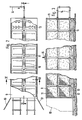
- Fig.2 eine Draufsicht auf eine Belüftungseinrichtung mit einem transportablen Container als geschlossenem Raum,
- Fig.3 einen Schnitt durch den Container nach Linie III-III,
- Fig.4 einen Schnitt durch den Container nach Linie IV-IV,
- Fig.5 eine schematische Darstellung einer Behandlungseinrichtung mit Schneckenförderern als geschlossenem Raum,
- Fig.5.1 eine vergrößerte Detaildarstellung eines Ausschnitts V.1 der Schnecke eines Schneckenförde rers,
- Fig.6 eine schematische Darstellung einer Behandlungseinrichtung mit einem geschlossenen Bandfilter
- 1 shows a schematic representation of a ventilation floor cleaning device with a closed treatment room,
- 2 shows a plan view of a ventilation device with a transportable container as a closed space,
- 3 shows a section through the container according to line III-III,
- 4 shows a section through the container according to line IV-IV,
- 5 shows a schematic representation of a treatment device with screw conveyors as a closed space,
- 5.1 an enlarged detailed view of a section V.1 of the screw of a screw conveyor,
- 6 shows a schematic representation of a treatment device with a closed band filter
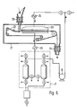
Bei der schematischen Darstellung des erfindungsgemäßen Verfahrens nach Fig. 1 ist der geschlossene Raum von einer auf einer Bodenplatte 1 dicht aufgesetzten Glocke 2 gebildet. Die Bodenplatte und die Glocke können aus beliebigem, jedoch gasdichtem Material sein. Insofern ist es sogar möglich, für die Glocke entsprechendes Zeltmaterial zu verwenden. Der ausgehobene von flüchtigen Schadstoffen zu reinigende Erdboden ist innerhalb der Glocke 2 als Haufwerk 3 auf der Bodenplatte 1 aufgeschichtet. Innerhalb des Haufwerkes 3 sind in geringem Abstand von der Bodenplatte perforierte Belüftungsrohre 4 mit Abstand zueinander angebracht. Durch diese Rohre 4 wird als ein quasi inertes Gas durch eine Leitung 5 Luft eingeblasen. Die durch das Haufwerk hindurchgeströmte, schadstoffbeladene Luft wird aus der Glocke 2 durch die Leitung 6 abgesaugt und einer Aktivkohle-Gas-Reinigungsanlage 7 zugeführt. Die Aktivkohle-Reinigungseinrichtung 7 besteht aus zwei mit Aktivkohle gefüllten Behältern, die so geschaltet sind, daß während der Adsorption der Schadgase an der Aktivkohle in dem einen Behälter der andere Behälter mit überhitztem Wasserdampf desorbiert wird. Das abgekühlte flüssige Gemisch aus Wasser und Schadstoff wird nach der Dichte getrennt und die wässrige Phase durch Stripen von gelösten Schadstoffen befreit. Die Gasphase wird wieder in den Kreislauf eingespeist und das dem Kreislauf entzogene von Schadstoffen befreite Wasser einem Vorfluter zugeleitet. Das von der Gasabführleitung 6 abgezogene Gas, das mit den Schadstoffen belastet ist, passiert zweckmäßigerweise einen Kompressor 8 (Seitenkanalverdichter) und einen Kühler 25, bevor es in die Gasreinigungsanlage 7 gelangt. Durch zu hohe Temperaturen wird die Adsorptionswirkung der Aktivkohle negativ beeinträchtigt. Nach Passieren der Gasreinigungsanlage 7 wird das Reingas wieder in einem Kompressor 8 komprimiert und gegebenenfalls über einen Wärmetauscher 24 wieder dem kontaminierten Erdboden über die Leitung 5 zugeführt.1, the closed space is formed by a bell 2 placed tightly on a
Außer der beschriebenen Gasreinigungsanlage 7 mit zwei selbstdesorbierenden parallel-geschalteten Aktivkohlebehältern ist eine Anlage mit einem Aktivkohlebehälter als Einweganlage möglich. Im Falle von schlecht adsorbierenden Substanzen, wie z. B. Vinylchlorid, müssen zur Verhinderung konkurrierender Adsorptionen eventuell zwei Anlagen hintereinander geschaltet werden.In addition to the described gas cleaning system 7 with two self-desorbing activated carbon containers connected in parallel, a system with an activated carbon container as a one-way system is possible. In the case of poorly adsorbing substances, such as. B. vinyl chloride, two systems may have to be connected in series to prevent competing adsorption.
Eine praktische Ausbildung einer Reinigungsanlage zeigen die Fig.2-4. Hier ist der geschlossene Raum ein transpor tabler kastenförmiger Stahl-Container 9. Ein solcher Container kann beispielsweise die genormten Abmessungen 12,2 m x 2,4 m x 2,6 m besitzen. Zu öffnen ist dieser Container an einer seiner schmalen Stirnseiten über gasdicht verschließbare Türen 10. Als poröse Behälter für die Aufnahme des zu reinigenden Materials dienen handelsübliche Gitterboxen 11, die in dem vorliegenden speziellen Beispiel die Größe 1 m x 1 m x 1,2 m haben können. Diese Gitterboxen 11 können jeweils zu zweit übereinander gestapelt auf in dem Container 9 nebeneinander verlegten zwei Schienenpaaren 12 in den Container eingebracht werden. Jede der Gitterboxen 11 ist mit im Abstand zu dem geschlossenen Boden der Box verlegten perforierten Belüftungsrohren 13 durchzogen. Die Perforation kann über den Umfang des einzelnen Rohres 13 ungleichmäßig verteilt sein, wobei der größte Perforationsanteil in der Regel geodätisch nach oben weist. Der Container 9 ist mit Luftzu- und Abführleitungen 14 bzw. 15 versehen. Die über die Leitung 15 abgesaugte Schadstoffe enthaltende Luft wird in einer hier nicht nochmals dargestellten Aktivkohle-Reinigungseinrichtung gereinigt und im Kreislauf über die Leitung 14 dem Container 9 erneut zugeführt. Die Aktivkohle-Reinigungseinrichtung kann insbesondere eine solche sein, wie sie bei dem ersten Ausführungsbeispiel im einzelnen beschrieben ist.Fig. 2-4 show a practical design of a cleaning system. Here the closed space is a transpor Tabular box-shaped
Die Beschickung der Gitterboxen 11 mit kontaminiertem Material, die Luftbeaufschlagung der Gitterboxen und deren Einbringen in den Container 9 geschieht wie folgt.The loading of the
Die einzelnen bereits mit Material befüllten oder noch vor der Containeröffnung zu befüllenden Gitterboxen 11 werden auf temporär vor die Container-Öffnung verlegte Schienen gesetzt.Die aus den Gitterboxen 11 herausragenden freien offenen Enden der Belüftungsrohre 13 werden über Schnell verschlüsse 16 mit Hilfe einzelner Rohrpaßstücken 17 untereinander verbunden. Das Einschieben der Gitterboxen 11 in den Container 9 kann paarweise bei jeweils übereinander gestapelten Boxen erfolgen oder es können auch sämtliche Boxen außerhalb des Containers miteinander verbunden und sodann gemeinsam in den Container 9 eingeschoben werden. Die Anschlüsse der Rohrpaßstücke an die Luftzu- und Abfuhrleitungen 14 und 15 können von außen hergestellt werden. Der Container der oben beschriebenen Größe nimmt in der angegebenen Anordnung vierundvierzig der oben maßlich ebenfalls angegebenen Gitterboxen 11 auf. Die Behandlung des Materials in dem Container 9 ertreckt sich in der Regel über Zeiträume zwischen Tagen und einigen Wochen. Abgesehen von der Art der jeweils vorliegenden Kontamination hängt die Behandlungsdauer auch wesentlich von dem durch den Container hindurchgeschickten Mengenstrom an Luft sowie deren Temperatur ab. Bei dem vorliegenden Beispiel eines Füllvolumens der Gitterboxen 11 von 1,2 Kubikmeter und einer Befüllung durch einen zu einem spezifischen Gewicht von 1,3 t/Kubikmeter aufbereiteten Material wird der Luftmengenstrom so festgelegt, daß 1 Kubikmeter Material pro Stunde von etwa 20 Kubikmeter Luft durchströmt wird. Die Temperatur der Luft wird bei Eintritt in den Container 9 mit ca. 50 Grad Celsius oder mehr eingestellt, wobei auch Temperaturen oberhalb 100 Grad Celcius möglich und vorteilhaft sein können. Um von dem Material stammende Partikelaustragungen in die Aktivkohlefilter zu vermeiden, empfiehlt es sich, die Gitterboxen 11 durch vliesförmige Filtermaterialien abzudecken.The
Ein besonderer Vorteil der Ausbildung des erforderlichen geschlossenen Raumes als Stahl-Container besteht darin, daß ein solcher Container ohne weiteres an den jeweiligen Ort einer Verunreinigung transportiert und dort zur Durchfüh rung der Reinigung eingesetzt werden kann. Es können selbstverständlich auch mehrere Container gleichzeitig an einem Behandlungsort eingesetzt werden. Zu diesem Zweck sind sämtliche Anlagenteile einschließlich der Gasreinigungseinrichtung modulartig vernetzbar ausgestaltet. Gegenüber der in situ Reinigung des Bodens kann man bei dem erfindungsgemäßen Verfahren die bei unterschiedlichen Materialien jeweils unterschiedlichen und vielfach im einzelnen zudem noch unbekannten Randbedingungen durch beispielsweise Auflockern und Anwärmen des Materials bei der Belüftung weitgehend optimieren.A particular advantage of the design of the required closed space as a steel container is that such a container easily transports it to the respective location of an impurity and carries it out there cleaning can be used. Of course, several containers can be used at the same time at one treatment location. For this purpose, all parts of the system, including the gas cleaning device, are designed to be networkable in a modular manner. Compared to in-situ cleaning of the floor, the process according to the invention can largely optimize the boundary conditions, which are different for different materials and are often still unknown in detail, for example by loosening and heating the material during ventilation.
Eine weitere Einrichtung zur Durchführung des erfindungsgemäßen Verfahrens sind die in Fig.5 und 5.1 gezeigten Schneckenförderer 18. Das Behandlungsgas wird durch diese wiederum im Kreislauf geführt, wobei ein Gegen- oder Gleichstrom zur Förderrichtung des aufzübereitenden Materials möglich ist. Das Besondere bei dieser Ausführungsform ist, daß die Schnecken 26 hohl ausgebildet sind und eine an das aufzübereitende Material angrenzende poröse mit dem Hohlraum verbundene Oberfläche aufweisen. Die Porosität kann dabei von einer Vielzahl einzelner Öffnungen 27 erzeugt sein. Von den Schneckenförderern 18 sind zweckmäßigerweise mehrere hintereinander geschaltet, um auf diese Weise möglichst ein Reinigungsverfahren mit kontinuierlich durchzusetzendem Material zu erhalten und dadurch mit extrem kurzen Behandlungszeiten auskommen zu können. Das Material wird über einen Aufgabetrichter 19 in den ersten Schneckenförderer 18 eingegeben und über eine Zellenradschleuse 20 aus dem dritten und damit bei dem gezeigten Beispiel letzten Schneckenförderer abgezogen. Die kurzen Behandlungszeiten werden hier durch die hervorragende Vermischung von direkt aus den Schnecken 26 austretendem Behandlungsgas mit dem durch die Schneckengänge geförderten Material erreicht. Diese verfahrenstechnische und apparativ günstige Vorgehensweise wird kombiniert mit einer besonderen Aufheizung der Desorptionsluft auf etwa 40 bis 220 Grad Celsius. Über einen entsprechenden Trocknungsvorgang des belasteten Materials wird eine sehr effektive und rasch arbeitende thermische Desorption eingeleitet, die eine besonders wirkungsvolle Abreinigung in stark bindigen Böden gewährleistet. Die heiße schadstoffbeladene Luft muß bei dieser Reinigungsvariante über einen Abscheider auf ca. 30 Grad Celcius abgekühlt werden, um eine ausreichende Absorption der verbleibenden gasförmigen Schadstoffe in der nachgeschalteten Aktivkohleanlage zu gewährleisten. Diese Verfahrensvariante kann kontinuierlich betrieben werden.Another device for carrying out the method according to the invention are the
Eine weitere kontinuierlich betreibbare Einrichtung zeigt Fig.6. Dort wird das zu behandelnde Material auf ein in einem geschlossenen Behälter 21 befindliches Endlos-Filterband 22 aufgegeben. Das Filterband 22 ist porös. Auf dem Filterband 22 wird das zu behandelnde Material durch den Behälter 21 transportiert und aus dem Behälter dekontaminiert abgezogen. Das zur Behandlung erforderliche inerte Gas wird wiederum im Kreislauf geführt, wobei die Regeneration des Gases in der bereits weiter oben beschriebenen Reinigungsanlage 7 erfolgt. Auf dem Weg von der Aufgabe auf das Filterband 22 wird das aufzübereitende Material von dem im Kreislauf geführten inerten Gas zur Aufnahme der Kontaminate durch das porös ausgebildete Filterband hindurch durchströmt. Um diese gezielte Durchströmung im Bereich des Filterbandes 22 zu erreichen, durchläuft das Filterband zusammen mit dem aufzübereitenden Material eine geschlossene von dem inerten Gas beaufschlagte Absaugevorrichtung 23. Vor dem Eintritt in die Absaugevorrichtung 23 wird das inerte Gas in einer Heizeinrichtung 24 erwärmt, während es vor Eintritt in die Aktivkohle-Reinigungsanlage 7 in einem Wärmetauscher 25 auf eine für die Aktivkohlefilteranlage zuträgliche Temperatur abgekühlt wird. Mit einer solchen Bandfilter-Anlage kann das erfindungsgemäße Verfahren wiederum kontinuierlich ausgeführt werden. Das Filterband 22 kann bezüglich seiner Umlaufgeschwindigkeit der Art und dem Grad der Kontamination des jeweils aufzübereitenden Materials angepaßt werden. Um die Porosität des Filterbandes 22 kontinuierlich aufrecht zu erhalten, kann das Band außerhalb der Absaugevorrichtung 23 eine Reinigungsanlage durchlaufen, in der es beispielsweise mit Wasser bespült oder mit Druckluft durchblasen wird.A further continuously operable device is shown in FIG. 6. There, the material to be treated is placed on an
Stoffe, die mit dem erfindungsgemäßen Verfahren und den zu dessen Durchführung vorgeschlagenen Einrichtungen eliminiert werden können, können beispielsweise sein: aliphatische und aromatische Kohlenwasserstoffe, halogenierte Kohlenwasserstoffe, insbesondere Chlorkohlenwasserstoffe, Fluorchlorkohlenwasserstoffe sowie leicht siedende Lösemittel, wie Tetrahydrofuran, Cyclohexanan usw. und Chlorbenzole, Alkohole, Phenole und Chlorphenole, etc. Insgesamt kommen jedoch alle niedrigsiedenden und/oder wasserdampfflüchtigen Verbindungen als entfernbar in Frage.Substances which can be eliminated by the process according to the invention and the facilities proposed for carrying it out can be, for example: aliphatic and aromatic hydrocarbons, halogenated hydrocarbons, in particular chlorinated hydrocarbons, chlorofluorocarbons and low-boiling solvents such as tetrahydrofuran, cyclohexanane etc. and chlorobenzenes, alcohols, Phenols and chlorophenols, etc. Overall, however, all low-boiling and / or steam-volatile compounds can be removed.
Das erfindungsgemäße Verfahren beruht im Grunde auf dem Prinzip, die entfernbaren flüchtigen Substanzen durch gezielte Begasung einerseits und Absaugung andererseits in einem geschlossenen Raum zu desorbieren oder thermisch zu desorbieren und die desorbierten Substanzen danach an einem Adsorber wie Aktivkohle zu adsorbieren und das Gas dabei zur Vermeidung einer Verunreinigung der Atmosphäre möglichst beständig im Kreis zu führen.The method according to the invention is basically based on the principle of desorbing or thermally desorbing the removable volatile substances by targeted fumigation on the one hand and suction on the other hand and then adsorbing the desorbed substances on an adsorber such as activated carbon and thereby avoiding the gas Pollution of the atmosphere as constant as possible.
Claims (17)
dadurch gekennzeichnet,
daß das zu reinigende Material in einen geschlossenen Raum eingebracht wird, in dem ein quasi inertes Gas in das Innere dieses Materials eingeführt wird, das nach Durchströmen des Materials aus dem geschlossenen Raum wieder abgezogen, gereinigt und diesem im Kreislauf bis zur Erzielung des gewünschten Reinheitsgrades des Materials wieder zugeführt wird.1. A method for removing volatile substances, in particular low-boiling and / or steam-volatile organic compounds, from soil and comparable materials, in particular those with a binding character, by suctioning off and cleaning the extracted gas contaminated with the substances to be removed,
characterized,
that the material to be cleaned is introduced into a closed space in which a quasi-inert gas is introduced into the interior of this material, which is drawn off again after flowing through the material from the closed space, cleaned and this in circulation until the desired degree of purity of the Material is fed again.
dadurch gekennzeichnet,
daß das Kreislaufgas erwärmt wird.2. The method according to claim 1,
characterized,
that the cycle gas is heated.
gekennzeichnet durch die merkmale
characterized by the characteristics
dadurch gekennzeichnet,
daß der geschlossene Raum ein verschließbarer transportabler Container (9) oder eine Kombination solcher Container ist.4. Device according to claim 3,
characterized,
that the closed space is a lockable portable container (9) or a combination of such containers.
dadurch gekennzeichnet,
daß die Gaszuführmittel der einzelnen Behälter (11) poröse Rohre (13) sind.5. Device according to one of the preceding claims,
characterized,
that the gas supply means of the individual containers (11) are porous tubes (13).
dadurch gekennzeichnet,
daß die Gaszuführmittel (13) der einzelnen Behälter (11) über Schnellverschlüsse (16) untereinander ver- und an die Gaszuleitung (14) anbindbar sind.6. Device according to one of the preceding claims,
characterized,
that the gas supply means (13) of the individual containers (11) can be connected to one another via quick-release fasteners (16) and connected to the gas supply line (14).
dadurch gekennzeichnet,
daß die porösen Behälter übliche Gitterboxen (11) sind.7. Device according to one of the preceding claims,
characterized,
that the porous containers are usual mesh boxes (11).
dadurch gekennzeichnet,
daß das in die porösen Behälter (11) eingefüllte aufzubereitende Material in sämtlichen Bereichen, in denen es nicht an undurchlässige Behälterwandteile direkt angrenzt, mit Filtermaterial abgedeckt ist.8. Device according to one of the preceding claims,
characterized,
that the material to be prepared filled into the porous container (11) is covered with filter material in all areas in which it does not directly adjoin impermeable container wall parts.
dadurch gekennzeichnet,
daß der Container (9) eine zu öffnende Seitenwand besitzt und auf seinem Boden mit senkrecht zu der zu öffnenden Seitenwand verlaufenden Schienen (12) oder Rollenförderern versehen ist, auf denen die porösen Behälter (9) über ggf. Räder in den Container (9) einschiebbar sind.9. Device according to one of the preceding claims,
characterized,
that the container (9) has a side wall that can be opened and is provided on its bottom with rails (12) or roller conveyors that run perpendicular to the side wall that is to be opened, on which the porous containers (9) are possibly inserted into the container (9) via wheels can be inserted.
dadurch gekennzeichnet,
daß der Container (9) mit zwei parallelen Schienenpaaren (12) oder Rollenförderern zur Aufnahme zweier benachbarter Behälterreihen ausgerüstet ist.10. Device according to claim 9,
characterized,
that the container (9) is equipped with two parallel pairs of rails (12) or roller conveyors for receiving two adjacent rows of containers.
dadurch gekennzeichnet,
daß die Gaszuführmittel (13) der einzelnen Behälter (9) über zwischen den beiden Behälterreihen verlaufende durch Schnellverschlüsse (16) miteinander koppelbare Leitungspaßstücke (17) miteinander verbunden sind.11. The device according to claim 10,
characterized,
that the gas supply means (13) of the individual containers (9) are connected to one another via line fittings (17) which can be coupled between the two rows of containers by means of quick-release fasteners (16).
dadurch gekennzeichnet,
daß der Container (9) an der der zu öffnenden Seitenwand gegenüberliegenden Wand einen durch Einfahren in Schienenrichtung selbstschließenden Leitungsverschluß für das koppelbare Leitungsstück (17) des angrenzenden Behälters (9) an die Gaszuleitung (14) aufweist.12. Device according to claim 11,
characterized,
that the container (9) on the wall opposite the side wall to be opened has a self-closing line retraction in the rail direction for the couplable line section (17) of the adjacent container (9) to the gas supply line (14).
dadurch gekennzeichnet,
daß mindestens jeweils zwei Behälter (11) übereinander gestapelt in den Container (9) einbringbar sind.13. Device according to one of the preceding claims,
characterized,
that at least two containers (11) stacked one above the other can be introduced into the container (9).
dadurch gekennzeichnet,
daß der geschlossene Raum ein Schneckenförderer (18) mit einer hohlen oberflächlich zumindest teilweise porösen Schnecke ist, durch welche das Reinigungsgas in das aufzubereitende von der Schnecke geförderte Material eingeführt wird.14. Device for performing the method according to claim 1 or 2,
characterized,
that the closed space is a screw conveyor (18) with a hollow, at least partially porous screw, through which the cleaning gas is introduced into the material to be processed, which is conveyed by the screw.
dadurch gekennzeichnet,
daß mehrere Schneckenförderer (18) hinter- und/oder nebeneinander geschaltet durchströmbar sind.15. Device according to claim 14,
characterized,
that several screw conveyors (18) can be flowed through in series and / or side by side.
dadurch gekennzeichnet,
daß der geschlossene Raum ein Bandfilter (Behälter 21 mit Filterband 22) ist, in dem das aufzübereitende Material auf einem umlaufenden porösen Endlos-Filterband vorzugsweise in einer Absaugevorrichtung (23) durchströmt wird.16. Device for carrying out the method according to claim 1 or 2,
characterized,
that the closed space is a belt filter (container 21 with filter belt 22), in which the material to be treated is flowed through on a rotating porous endless filter belt, preferably in a suction device (23).
dadurch gekennzeichnet,
daß die an die Atmosphäre angrenzenden Teile der Einrichtung wärmeisoliert sind.17. Device according to one of the preceding claims,
characterized,
that the atmospheric parts of the device are thermally insulated.
Applications Claiming Priority (2)
| Application Number | Priority Date | Filing Date | Title |
|---|---|---|---|
| DE3921591A DE3921591A1 (en) | 1989-06-30 | 1989-06-30 | METHOD AND DEVICE FOR REMOVING VOLATILE POLLUTANTS FROM EARTH SOILS |
| DE3921591 | 1989-06-30 |
Publications (3)
| Publication Number | Publication Date |
|---|---|
| EP0405067A2 true EP0405067A2 (en) | 1991-01-02 |
| EP0405067A3 EP0405067A3 (en) | 1991-08-28 |
| EP0405067B1 EP0405067B1 (en) | 1995-01-04 |
Family
ID=6384061
Family Applications (1)
| Application Number | Title | Priority Date | Filing Date |
|---|---|---|---|
| EP90106351A Expired - Lifetime EP0405067B1 (en) | 1989-06-30 | 1990-04-03 | Device for removing volatile contaminants from soil or similar |
Country Status (5)
| Country | Link |
|---|---|
| EP (1) | EP0405067B1 (en) |
| JP (1) | JPH03118083A (en) |
| AT (1) | ATE116578T1 (en) |
| DD (1) | DD296210A5 (en) |
| DE (2) | DE3921591A1 (en) |
Cited By (13)
| Publication number | Priority date | Publication date | Assignee | Title |
|---|---|---|---|---|
| EP0557623A3 (en) * | 1992-02-25 | 1993-09-22 | Hrubetz Environmental Services, Inc. | Mobile material decontamination apparatus |
| EP0540342A3 (en) * | 1991-10-30 | 1994-02-09 | Westinghouse Electric Corp | |
| EP0562095A4 (en) * | 1991-09-26 | 1994-02-16 | Maynard D. Ikenberry | |
| DE9402553U1 (en) * | 1994-02-16 | 1994-04-14 | Hydrogeologie GmbH, 99734 Nordhausen | Plant for cleaning contaminated bulk goods |
| US5482402A (en) * | 1990-02-05 | 1996-01-09 | Hrubetz Environmental Services, Inc. | Method and apparatus for heating subsurface soil for decontamination |
| EP0715902A1 (en) * | 1994-10-27 | 1996-06-12 | Franz Dipl.-Ing Kettenbauer | Method and plant for the thermal separation of pollutants from contaminated matter |
| EP0739659A1 (en) * | 1995-04-24 | 1996-10-30 | Robert Mittelmeier | Method and plant for cleaning contaminated materials, particularly soils |
| WO2003055615A1 (en) * | 2002-01-03 | 2003-07-10 | Hood Environmental Engineering Ltd. | Thermal remediation process |
| WO2004101186A1 (en) * | 2003-05-17 | 2004-11-25 | Mel Limited | Receptacle and methods of decontamination using said receptacle |
| US7214390B2 (en) * | 2003-02-07 | 2007-05-08 | Barmensen Labs, Llc | Topical compositions for enhancing sexual responsiveness |
| US8037617B2 (en) | 2007-03-26 | 2011-10-18 | Russell Gary Kossowan | Contaminated soil remediation apparatus |
| CN107309257A (en) * | 2017-07-25 | 2017-11-03 | 浙江大学 | Heat reinforcing gas phase extraction stain soil restoring device and its method |
| US10016795B2 (en) | 2012-12-13 | 2018-07-10 | Exxonmobil Research And Engineering Company | Remediation of contaminated particulate materials |
Families Citing this family (9)
| Publication number | Priority date | Publication date | Assignee | Title |
|---|---|---|---|---|
| DE4119149A1 (en) * | 1991-03-22 | 1992-11-05 | Hak Anlagenbau Gmbh Fuer Verfa | Gas purged desorption for solids heated by electromagnetic radiation - partic. IR, UV, microwave, and low frequency energy in removal of volatilisable organics |
| DE4111585C2 (en) * | 1991-04-10 | 2000-09-28 | Reiner Schuette | Procedure for checking the distribution of liquid or gaseous media in the ground |
| JPH0576618A (en) * | 1991-09-13 | 1993-03-30 | Japan Organo Co Ltd | Purification processing method of earth polluted with organic solvent and purification processing device |
| DE4303722C1 (en) * | 1993-02-10 | 1994-05-05 | Metallgesellschaft Ag | Decontamination of soil, sand, sludge or solid aggregate or residue - by heating with recycled hot gas or super-heated steam contg. oxidant, removing dust, condensing impurities and chemical or physical removal |
| DE4314557A1 (en) * | 1993-05-04 | 1994-11-10 | Lbe Beheizungseinrichtungen | Method and device for decontamination of bulk material containing harmful substances |
| DE4337623C2 (en) * | 1993-11-04 | 1996-10-17 | Manfred Dipl Chem D Haselhorst | Process for dewatering and deoiling oil sludge and device for carrying out the process |
| DE19901996B4 (en) * | 1999-01-20 | 2012-07-12 | Umweltschutz Nord Gmbh & Co. | Method for reducing volatiles in soils and apparatus for carrying out this method |
| JP4577728B2 (en) * | 2002-03-15 | 2010-11-10 | 鹿島建設株式会社 | Oil-contaminated soil treatment equipment combined with existing asphalt plant |
| DE102009007302C5 (en) * | 2009-02-03 | 2019-04-25 | Grebo License Gmbh & Co. Kg | Method and device for the hydrothermal carbonization of biomass |
Family Cites Families (17)
| Publication number | Priority date | Publication date | Assignee | Title |
|---|---|---|---|---|
| NL8400652A (en) * | 1984-02-29 | 1985-09-16 | Ecotechniek Bv | METHOD AND APPARATUS FOR CLEANING SOIL CONTAMINATED WITH TOXIC SUBSTANCES |
| US4726301A (en) * | 1985-03-13 | 1988-02-23 | Ormeaux Farrell P Des | System for extracting contaminants and hydrocarbons from cuttings waste in oil well drilling |
| DE3601490A1 (en) * | 1986-01-20 | 1987-07-30 | Hoelter Heinz | Treatment of contaminated soils |
| DE3604761A1 (en) * | 1986-02-14 | 1987-08-20 | Possehl & Co Mbh L | METHOD AND DEVICE FOR THE TREATMENT OF GRAINY SUBSTANCES |
| DE3706684A1 (en) * | 1986-04-08 | 1987-10-15 | Kurt Von Dipl Chem D Beckerath | METHOD FOR REMOVING VOLATILE POLLUTANTS FROM CONTAMINATED SOILS, SANDS, SLURRY AND COMPARABLE SOLID AGGREGATES AND RESIDUES |
| DE3623939A1 (en) * | 1986-07-16 | 1988-01-21 | Orenstein & Koppel Ag | METHOD AND SYSTEM FOR PROCESSING CONTAMINATED SOILS AND SIMILAR MATERIAL |
| US4700638A (en) * | 1986-08-11 | 1987-10-20 | M & S Engineering And Manufacturing Co., Inc. | Method and apparatus for soil detoxification |
| US4667609A (en) * | 1986-09-08 | 1987-05-26 | Robert Hardison | Apparatus and method for treatment of soil contaminated with hydrocarbons |
| US4738206A (en) * | 1986-09-16 | 1988-04-19 | Roy F. Weston, Inc. | Apparatus and method for low temperature thermal stripping of volatile organic compounds from soil |
| US4745850A (en) * | 1986-12-10 | 1988-05-24 | Shell Oil Company | Diffusive venting of soil contaminated with volatile compounds |
| ATE74542T1 (en) * | 1987-01-15 | 1992-04-15 | Hoelscher Richard | EQUIPMENT FOR STORAGE AND TREATMENT OF SOIL CONTAMED WITH POLLUTANTS. |
| DE3716275A1 (en) * | 1987-05-15 | 1988-11-24 | Westfaelische Berggewerkschaft | Process and apparatus for the thermal decontamination of contaminated soils |
| NL8701963A (en) * | 1987-08-20 | 1989-03-16 | Heidemij Uitvoering | Method for cleaning contaminated ground using heated medium - uses injection lance with medium heater and vacuum lance, both vertical and perforated with conical ends and helical blades |
| DE3728299A1 (en) * | 1987-08-25 | 1989-03-09 | Ieg Ind Engineering Gmbh | METHOD AND ARRANGEMENT FOR DRIVING LIGHT VEGETABLE IMPURITIES FROM THE GROUND |
| DE3738704A1 (en) * | 1987-11-14 | 1989-05-24 | Phytec Physikalisch Tech Anlag | Process and plant for the thermal decontamination of contaminated, excavated soil |
| DE3809115A1 (en) * | 1988-03-18 | 1989-09-28 | Artur Richard Greul | Process for decontaminating substances with a hollow-screw combination |
| DE3905133A1 (en) * | 1988-05-26 | 1989-11-30 | Zueblin Ag | Process for removing readily volatile constituents from soils |
-
1989
- 1989-06-30 DE DE3921591A patent/DE3921591A1/en not_active Withdrawn
-
1990
- 1990-04-03 AT AT90106351T patent/ATE116578T1/en active
- 1990-04-03 EP EP90106351A patent/EP0405067B1/en not_active Expired - Lifetime
- 1990-04-03 DE DE59008175T patent/DE59008175D1/en not_active Expired - Fee Related
- 1990-06-29 JP JP2170368A patent/JPH03118083A/en active Pending
- 1990-06-29 DD DD90342287A patent/DD296210A5/en not_active IP Right Cessation
Cited By (15)
| Publication number | Priority date | Publication date | Assignee | Title |
|---|---|---|---|---|
| US5482402A (en) * | 1990-02-05 | 1996-01-09 | Hrubetz Environmental Services, Inc. | Method and apparatus for heating subsurface soil for decontamination |
| EP0562095A4 (en) * | 1991-09-26 | 1994-02-16 | Maynard D. Ikenberry | |
| EP0540342A3 (en) * | 1991-10-30 | 1994-02-09 | Westinghouse Electric Corp | |
| EP0557623A3 (en) * | 1992-02-25 | 1993-09-22 | Hrubetz Environmental Services, Inc. | Mobile material decontamination apparatus |
| AU669134B2 (en) * | 1992-02-25 | 1996-05-30 | Hrubetz Environmental Services, Inc | Mobile material decontamination apparatus |
| DE9402553U1 (en) * | 1994-02-16 | 1994-04-14 | Hydrogeologie GmbH, 99734 Nordhausen | Plant for cleaning contaminated bulk goods |
| EP0715902A1 (en) * | 1994-10-27 | 1996-06-12 | Franz Dipl.-Ing Kettenbauer | Method and plant for the thermal separation of pollutants from contaminated matter |
| EP0739659A1 (en) * | 1995-04-24 | 1996-10-30 | Robert Mittelmeier | Method and plant for cleaning contaminated materials, particularly soils |
| WO2003055615A1 (en) * | 2002-01-03 | 2003-07-10 | Hood Environmental Engineering Ltd. | Thermal remediation process |
| US7214390B2 (en) * | 2003-02-07 | 2007-05-08 | Barmensen Labs, Llc | Topical compositions for enhancing sexual responsiveness |
| WO2004101186A1 (en) * | 2003-05-17 | 2004-11-25 | Mel Limited | Receptacle and methods of decontamination using said receptacle |
| US8037617B2 (en) | 2007-03-26 | 2011-10-18 | Russell Gary Kossowan | Contaminated soil remediation apparatus |
| US10016795B2 (en) | 2012-12-13 | 2018-07-10 | Exxonmobil Research And Engineering Company | Remediation of contaminated particulate materials |
| US10682679B2 (en) | 2012-12-13 | 2020-06-16 | Exxonmobil Research And Engineering Company | Remediation of contaminated particulate materials |
| CN107309257A (en) * | 2017-07-25 | 2017-11-03 | 浙江大学 | Heat reinforcing gas phase extraction stain soil restoring device and its method |
Also Published As
| Publication number | Publication date |
|---|---|
| EP0405067B1 (en) | 1995-01-04 |
| DD296210A5 (en) | 1991-11-28 |
| DE3921591A1 (en) | 1991-01-03 |
| DE59008175D1 (en) | 1995-02-16 |
| JPH03118083A (en) | 1991-05-20 |
| EP0405067A3 (en) | 1991-08-28 |
| ATE116578T1 (en) | 1995-01-15 |
Similar Documents
| Publication | Publication Date | Title |
|---|---|---|
| EP0405067A2 (en) | Device for removing volatile contaminants from soil or similar | |
| DE69220351T2 (en) | Mobile device for decontamination of material | |
| DE2626939A1 (en) | METHOD AND DEVICE FOR SEPARATING UNWANTED GAS-FORMED COMPONENTS FROM AN EXHAUST GAS | |
| DE2461562B2 (en) | Gas adsorber vessel | |
| EP0357653B1 (en) | Feed inlet floor for mobile bed reactors | |
| DE2607590A1 (en) | PROCESS FOR CONTINUOUSLY CLEANING AN EXHAUST GAS CONTAINING GAS POLLUTION | |
| DE4440464C1 (en) | Disposable floating bio:filter preventing odour from large bodies of fluid | |
| DE3625488C2 (en) | Device for expelling volatile impurities from liquids | |
| DE19851793A1 (en) | Dryer for paste like material incorporates gas flow generator, support, pipe and fan | |
| DE19924130A1 (en) | Removal of solid particles from gas by piping gas to be filtered to the filter together with a powder or dust filtration-aid medium which is reusable | |
| EP1220712B1 (en) | Method, device and installation for treating fluids on at least one bulk material layer | |
| DD280844A5 (en) | METHOD AND DEVICE FOR TREATING A POISONOULE DEPONIA AT PLACE AND PLACE | |
| DE3421719A1 (en) | Portable device for decontamination of objects | |
| EP0676989B1 (en) | Reactor for purifying contaminated solids | |
| DE4107982A1 (en) | METHOD AND DEVICE FOR ELIMINATING TRITIUM FROM POLLUTED OBJECTS | |
| DE69811121T2 (en) | PROCESS AND APPARATUS FOR TREATING WASTE | |
| DE69809261T2 (en) | METHOD AND DEVICE FOR DECONTAMINATING FLOORS | |
| DE4240054C1 (en) | Composting assembly for degradable waste - has cells constantly connected to main exhaust suction when door is closed with additional suction when door is opened | |
| DE69119602T2 (en) | SYSTEM AND METHOD FOR DETOXING EARTH GROUND | |
| DE19901996B4 (en) | Method for reducing volatiles in soils and apparatus for carrying out this method | |
| DE19541918C2 (en) | Process for desorption of compounds bound to adsorbent and desorption applicator | |
| DE69109735T2 (en) | Device for extracting gas from a tank container. | |
| DE4220493A1 (en) | adsorber | |
| DE102007013498B4 (en) | Adsorption device and system for the adsorption of highly toxic substances from the exhaust air of chemical processing plants | |
| DD291936A5 (en) | METHOD FOR REMOVING GASES AND HORIZONTAL REACTOR TO CARRY OUT THE PROCEDURE |
Legal Events
| Date | Code | Title | Description |
|---|---|---|---|
| PUAI | Public reference made under article 153(3) epc to a published international application that has entered the european phase |
Free format text: ORIGINAL CODE: 0009012 |
|
| AK | Designated contracting states |
Kind code of ref document: A2 Designated state(s): AT BE CH DE FR GB IT LI LU NL |
|
| PUAL | Search report despatched |
Free format text: ORIGINAL CODE: 0009013 |
|
| AK | Designated contracting states |
Kind code of ref document: A3 Designated state(s): AT BE CH DE FR GB IT LI LU NL |
|
| 17P | Request for examination filed |
Effective date: 19920130 |
|
| 17Q | First examination report despatched |
Effective date: 19930811 |
|
| GRAA | (expected) grant |
Free format text: ORIGINAL CODE: 0009210 |
|
| AK | Designated contracting states |
Kind code of ref document: B1 Designated state(s): AT BE CH DE FR GB IT LI LU NL |
|
| PG25 | Lapsed in a contracting state [announced via postgrant information from national office to epo] |
Ref country code: IT Free format text: LAPSE BECAUSE OF FAILURE TO SUBMIT A TRANSLATION OF THE DESCRIPTION OR TO PAY THE FEE WITHIN THE PRESCRIBED TIME-LIMIT;WARNING: LAPSES OF ITALIAN PATENTS WITH EFFECTIVE DATE BEFORE 2007 MAY HAVE OCCURRED AT ANY TIME BEFORE 2007. THE CORRECT EFFECTIVE DATE MAY BE DIFFERENT FROM THE ONE RECORDED. Effective date: 19950104 Ref country code: NL Effective date: 19950104 Ref country code: GB Effective date: 19950104 Ref country code: BE Effective date: 19950104 Ref country code: FR Effective date: 19950104 |
|
| REF | Corresponds to: |
Ref document number: 116578 Country of ref document: AT Date of ref document: 19950115 Kind code of ref document: T |
|
| REF | Corresponds to: |
Ref document number: 59008175 Country of ref document: DE Date of ref document: 19950216 |
|
| PG25 | Lapsed in a contracting state [announced via postgrant information from national office to epo] |
Ref country code: AT Effective date: 19950403 |
|
| PG25 | Lapsed in a contracting state [announced via postgrant information from national office to epo] |
Ref country code: LI Effective date: 19950430 Ref country code: LU Free format text: LAPSE BECAUSE OF NON-PAYMENT OF DUE FEES Effective date: 19950430 Ref country code: CH Effective date: 19950430 |
|
| EN | Fr: translation not filed | ||
| NLV1 | Nl: lapsed or annulled due to failure to fulfill the requirements of art. 29p and 29m of the patents act | ||
| GBV | Gb: ep patent (uk) treated as always having been void in accordance with gb section 77(7)/1977 [no translation filed] |
Effective date: 19950104 |
|
| PLBE | No opposition filed within time limit |
Free format text: ORIGINAL CODE: 0009261 |
|
| STAA | Information on the status of an ep patent application or granted ep patent |
Free format text: STATUS: NO OPPOSITION FILED WITHIN TIME LIMIT |
|
| REG | Reference to a national code |
Ref country code: CH Ref legal event code: PL |
|
| 26N | No opposition filed | ||
| PGFP | Annual fee paid to national office [announced via postgrant information from national office to epo] |
Ref country code: DE Payment date: 19990428 Year of fee payment: 10 |
|
| PG25 | Lapsed in a contracting state [announced via postgrant information from national office to epo] |
Ref country code: DE Free format text: LAPSE BECAUSE OF NON-PAYMENT OF DUE FEES Effective date: 20000430 |