EP0715902A1 - Method and plant for the thermal separation of pollutants from contaminated matter - Google Patents
Method and plant for the thermal separation of pollutants from contaminated matter Download PDFInfo
- Publication number
- EP0715902A1 EP0715902A1 EP94116974A EP94116974A EP0715902A1 EP 0715902 A1 EP0715902 A1 EP 0715902A1 EP 94116974 A EP94116974 A EP 94116974A EP 94116974 A EP94116974 A EP 94116974A EP 0715902 A1 EP0715902 A1 EP 0715902A1
- Authority
- EP
- European Patent Office
- Prior art keywords
- steam
- treated
- treatment
- unit
- conveyor belt
- Prior art date
- Legal status (The legal status is an assumption and is not a legal conclusion. Google has not performed a legal analysis and makes no representation as to the accuracy of the status listed.)
- Withdrawn
Links
- 238000000034 method Methods 0.000 title claims abstract description 33
- 239000003344 environmental pollutant Substances 0.000 title claims description 9
- 231100000719 pollutant Toxicity 0.000 title claims description 9
- 238000000926 separation method Methods 0.000 title claims description 6
- XLYOFNOQVPJJNP-UHFFFAOYSA-N water Substances O XLYOFNOQVPJJNP-UHFFFAOYSA-N 0.000 claims abstract description 22
- 239000007787 solid Substances 0.000 claims abstract description 12
- 239000000428 dust Substances 0.000 claims abstract description 8
- 238000007669 thermal treatment Methods 0.000 claims abstract description 3
- 239000000463 material Substances 0.000 claims description 43
- 239000007789 gas Substances 0.000 claims description 14
- 238000004140 cleaning Methods 0.000 claims description 11
- 238000010025 steaming Methods 0.000 claims description 10
- 239000012071 phase Substances 0.000 claims description 8
- 239000003921 oil Substances 0.000 claims description 5
- 238000001223 reverse osmosis Methods 0.000 claims description 5
- 239000008346 aqueous phase Substances 0.000 claims description 4
- 238000009833 condensation Methods 0.000 claims description 4
- 230000005494 condensation Effects 0.000 claims description 4
- 238000007872 degassing Methods 0.000 claims description 4
- 231100001240 inorganic pollutant Toxicity 0.000 claims description 4
- 238000011068 loading method Methods 0.000 claims description 4
- 238000000108 ultra-filtration Methods 0.000 claims description 4
- 238000009835 boiling Methods 0.000 claims description 3
- 238000006243 chemical reaction Methods 0.000 claims description 3
- 238000002485 combustion reaction Methods 0.000 claims description 3
- 238000004519 manufacturing process Methods 0.000 claims description 3
- 239000002689 soil Substances 0.000 claims description 3
- 238000007740 vapor deposition Methods 0.000 claims description 3
- 238000009834 vaporization Methods 0.000 claims description 3
- 230000008016 vaporization Effects 0.000 claims description 3
- 238000007599 discharging Methods 0.000 claims description 2
- 239000006148 magnetic separator Substances 0.000 claims 1
- 239000000356 contaminant Substances 0.000 abstract description 4
- 239000002245 particle Substances 0.000 abstract 1
- 238000004821 distillation Methods 0.000 description 10
- OKTJSMMVPCPJKN-UHFFFAOYSA-N Carbon Chemical compound [C] OKTJSMMVPCPJKN-UHFFFAOYSA-N 0.000 description 6
- 229910052717 sulfur Inorganic materials 0.000 description 4
- NINIDFKCEFEMDL-UHFFFAOYSA-N Sulfur Chemical compound [S] NINIDFKCEFEMDL-UHFFFAOYSA-N 0.000 description 3
- 238000001816 cooling Methods 0.000 description 3
- 239000010419 fine particle Substances 0.000 description 3
- 210000001035 gastrointestinal tract Anatomy 0.000 description 3
- 238000010438 heat treatment Methods 0.000 description 3
- 229910052753 mercury Inorganic materials 0.000 description 3
- 239000000203 mixture Substances 0.000 description 3
- 239000000126 substance Substances 0.000 description 3
- 239000011593 sulfur Substances 0.000 description 3
- ZAMOUSCENKQFHK-UHFFFAOYSA-N Chlorine atom Chemical compound [Cl] ZAMOUSCENKQFHK-UHFFFAOYSA-N 0.000 description 2
- BPQQTUXANYXVAA-UHFFFAOYSA-N Orthosilicate Chemical compound [O-][Si]([O-])([O-])[O-] BPQQTUXANYXVAA-UHFFFAOYSA-N 0.000 description 2
- 229910052801 chlorine Inorganic materials 0.000 description 2
- 239000000460 chlorine Substances 0.000 description 2
- 238000011109 contamination Methods 0.000 description 2
- 238000010924 continuous production Methods 0.000 description 2
- QSHDDOUJBYECFT-UHFFFAOYSA-N mercury Chemical compound [Hg] QSHDDOUJBYECFT-UHFFFAOYSA-N 0.000 description 2
- 238000002156 mixing Methods 0.000 description 2
- 229910001220 stainless steel Inorganic materials 0.000 description 2
- 239000010935 stainless steel Substances 0.000 description 2
- 238000011144 upstream manufacturing Methods 0.000 description 2
- 239000002699 waste material Substances 0.000 description 2
- PXGOKWXKJXAPGV-UHFFFAOYSA-N Fluorine Chemical compound FF PXGOKWXKJXAPGV-UHFFFAOYSA-N 0.000 description 1
- 239000000654 additive Substances 0.000 description 1
- 238000005054 agglomeration Methods 0.000 description 1
- 230000002776 aggregation Effects 0.000 description 1
- 238000004887 air purification Methods 0.000 description 1
- 239000007864 aqueous solution Substances 0.000 description 1
- 229910052785 arsenic Inorganic materials 0.000 description 1
- RQNWIZPPADIBDY-UHFFFAOYSA-N arsenic atom Chemical compound [As] RQNWIZPPADIBDY-UHFFFAOYSA-N 0.000 description 1
- 239000011230 binding agent Substances 0.000 description 1
- 239000003990 capacitor Substances 0.000 description 1
- 150000001805 chlorine compounds Chemical class 0.000 description 1
- 239000012459 cleaning agent Substances 0.000 description 1
- 239000011538 cleaning material Substances 0.000 description 1
- 230000001112 coagulating effect Effects 0.000 description 1
- 238000007796 conventional method Methods 0.000 description 1
- 238000005260 corrosion Methods 0.000 description 1
- 230000007797 corrosion Effects 0.000 description 1
- 238000010586 diagram Methods 0.000 description 1
- 238000009826 distribution Methods 0.000 description 1
- 238000001704 evaporation Methods 0.000 description 1
- 230000008020 evaporation Effects 0.000 description 1
- 229910052731 fluorine Inorganic materials 0.000 description 1
- 239000011737 fluorine Substances 0.000 description 1
- 238000005469 granulation Methods 0.000 description 1
- 230000003179 granulation Effects 0.000 description 1
- 239000012535 impurity Substances 0.000 description 1
- 239000007791 liquid phase Substances 0.000 description 1
- 229910052751 metal Inorganic materials 0.000 description 1
- 239000002184 metal Substances 0.000 description 1
- 150000002825 nitriles Chemical class 0.000 description 1
- 239000007800 oxidant agent Substances 0.000 description 1
- 238000000746 purification Methods 0.000 description 1
- 238000004064 recycling Methods 0.000 description 1
- 230000001105 regulatory effect Effects 0.000 description 1
- 239000010802 sludge Substances 0.000 description 1
- 238000001179 sorption measurement Methods 0.000 description 1
- 238000003892 spreading Methods 0.000 description 1
- 239000000758 substrate Substances 0.000 description 1
Images


Classifications
-
- C—CHEMISTRY; METALLURGY
- C02—TREATMENT OF WATER, WASTE WATER, SEWAGE, OR SLUDGE
- C02F—TREATMENT OF WATER, WASTE WATER, SEWAGE, OR SLUDGE
- C02F1/00—Treatment of water, waste water, or sewage
- C02F1/44—Treatment of water, waste water, or sewage by dialysis, osmosis or reverse osmosis
-
- B—PERFORMING OPERATIONS; TRANSPORTING
- B09—DISPOSAL OF SOLID WASTE; RECLAMATION OF CONTAMINATED SOIL
- B09B—DISPOSAL OF SOLID WASTE NOT OTHERWISE PROVIDED FOR
- B09B3/00—Destroying solid waste or transforming solid waste into something useful or harmless
-
- B—PERFORMING OPERATIONS; TRANSPORTING
- B09—DISPOSAL OF SOLID WASTE; RECLAMATION OF CONTAMINATED SOIL
- B09C—RECLAMATION OF CONTAMINATED SOIL
- B09C1/00—Reclamation of contaminated soil
- B09C1/06—Reclamation of contaminated soil thermally
-
- C—CHEMISTRY; METALLURGY
- C02—TREATMENT OF WATER, WASTE WATER, SEWAGE, OR SLUDGE
- C02F—TREATMENT OF WATER, WASTE WATER, SEWAGE, OR SLUDGE
- C02F1/00—Treatment of water, waste water, or sewage
- C02F1/44—Treatment of water, waste water, or sewage by dialysis, osmosis or reverse osmosis
- C02F1/441—Treatment of water, waste water, or sewage by dialysis, osmosis or reverse osmosis by reverse osmosis
-
- C—CHEMISTRY; METALLURGY
- C02—TREATMENT OF WATER, WASTE WATER, SEWAGE, OR SLUDGE
- C02F—TREATMENT OF WATER, WASTE WATER, SEWAGE, OR SLUDGE
- C02F1/00—Treatment of water, waste water, or sewage
- C02F1/44—Treatment of water, waste water, or sewage by dialysis, osmosis or reverse osmosis
- C02F1/444—Treatment of water, waste water, or sewage by dialysis, osmosis or reverse osmosis by ultrafiltration or microfiltration
-
- C—CHEMISTRY; METALLURGY
- C02—TREATMENT OF WATER, WASTE WATER, SEWAGE, OR SLUDGE
- C02F—TREATMENT OF WATER, WASTE WATER, SEWAGE, OR SLUDGE
- C02F1/00—Treatment of water, waste water, or sewage
- C02F1/44—Treatment of water, waste water, or sewage by dialysis, osmosis or reverse osmosis
- C02F1/447—Treatment of water, waste water, or sewage by dialysis, osmosis or reverse osmosis by membrane distillation
Definitions
- the invention relates to a process for the thermal separation of organic and / or inorganic pollutants from contaminated material to be treated, such as soils, sludges, mill scale and the like, with hot gases, which are then dedusted, condensed and subjected to condensate cleaning. Furthermore, the invention relates to a plant for performing the method.
- the known method does not allow continuous operation, since the furnace has to be loaded with the material to be treated and emptied later.
- complex equipment such as chain scraper conveyors are required.
- the return of 80 to 90% of the water vapor-containing contaminated treatment gases into the furnace causes high corrosion risks due to the introduced steam-air / pollutant mixture, which represents an aggressive furnace atmosphere.
- the invention is based on the object of improving a process for the thermal separation of organic and / or inorganic pollutants from contaminated material to be treated in such a way that, in the context of a continuous process without an oven, avoiding a high excess of air, all organic and inorganic contaminations Nature can be removed from the material to be treated in an economical manner.
- the object is achieved according to the invention in that the material to be treated is spread over a gas-permeable substrate continuously or stepwise forward from a feed zone to a removal zone in a predetermined layer thickness, such that only superheated steam at a temperature of ⁇ 700 ° C.
- the heat content of the superheated steam is initially exploited in the continuous process to dry the material to be treated in the application zone of the reaction chamber, and the now dry material to be treated is heated by the superheated steam at a temperature of ⁇ 700 ° C. in order to avoid the contamination to evaporate.
- the boiling points are approximately between 400 ° C. and 500 ° C., as is also the case with inorganic pollutants, such as mercury, chlorine, fluorine and sulfur, in dissolved form or crystalline form. Even easily releasable cyanides can be evaporated by the hot steam treatment. A separate heating is not necessary.
- the treatment is preferably carried out with superheated steam at 700 ° C. and a pressure of 1.5 bar, the layer thickness advantageously being set to between 200 mm and 500 mm.
- the treated goods are freed from pollutants, for example a clean floor.
- the hot vapor vapors now contaminated are removed, dedusted and condensed in a manner known per se, the dust obtained advantageously being returned to the process in front of the feed zone, possibly after granulating, pelleting or coagulating.
- the condensate from the condensation is preferably processed in a three-phase separator, the aqueous phase being used as boiler feed water for the production of superheated steam.
- the vacuum air generated during the condensation is fed to an adsorber, wherein activated carbon can advantageously be used for the adsorption.
- activated carbon can advantageously be used for the adsorption.
- Pollutants such as chlorine and sulfur are removed from the air, so that a considerable part of the air can be fed to the burner of the boiler system as combustion air.
- the material to be treated which has been cleaned by thermal treatment, subsequently be subjected to post-treatment by means of process media in a reactor column.
- the reactor column can be operated in a parallel steam cycle.
- the method according to the invention can be carried out with little economic outlay and a high quality of the pollutant separation is achieved by thermal means.
- the high quality of cleaning with the simple steam flow method through the moving layer of the material to be treated is surprising. Compared to conventional methods, good mixing of the material to be treated and steam is achieved and the individual contaminants can be separated in a simple manner with little effort. Large quantities of exhaust air are avoided, as are complex exhaust gas purification processes.
- a system which consists of a loading unit, a steaming unit, a dispensing unit for the material to be treated, a steam generator and a vapor cleaning device, the steaming unit comprising an essentially gas-tight housing with a feed lock and a discharge lock between which is arranged a gas-permeable conveyor belt for the material to be treated, under which are arranged supply nozzles for superheated steam distributed over the entire surface.
- a second conveyor belt can be arranged below the conveyor belt for the material to be treated, with the opposite direction of conveyance for collecting and discharging the very fine materials, which can again be fed to the application zone of the steaming unit by means of an elevator.
- the steaming device consists of a vapor-permeable conveyor belt 5, which is fed with material via an access lock 16.
- the layer thickness can be regulated by the feed speed of the belt 5.
- a further conveyor belt is arranged beneath the belt 5, by means of which fine material falling through the belt 5 is fed out of the steaming device to an elevator 15, by means of which the material is returned to the circuit.
- the elevator 15 conveys the fine material back onto the conveyor belt 4.
- the cleaned material is fed via an exit lock 17 to a conveyor belt 6, which in the exemplary embodiment shown is a cooling belt. Residual steam is drawn off via a steam outlet and also returned to the circuit. After the cooling belt, the cleaned goods are made available for recycling.
- boiler feed water is heated to about 145 ° C. at a pressure of preferably 1.5 bar by means of a burner which operates in a range of 1250 ° C.
- a superheater 8 steam with a temperature of preferably 700 ° C is generated, which is fed to a steam distributor at a substantially constant pressure of between 0.5 and 1.5 bar.
- the steam is introduced into the steaming system 5 via the steam distributor and is guided there into the area between the upper run and the lower run of the steam-permeable conveyor belt, covering the entire surface. This ensures that steam flows through the layer on the conveyor belt to be cleaned evenly.
- the goods are cleaned from KW, CKW, PAK, CI, S and Hg, among others.
- the vaporization is continued over a predetermined period of time. Since the steaming device, which is also referred to as a distillation reactor, is essentially gas-tight, a corresponding pressure of, for example, 1.5 bar can be maintained.
- the steam is fed from the distillation reactor via lines to a fine particle dust filter 9, in which the vapors are dedusted, for example, ⁇ 10 mg / Ncbm.
- the fine particle dust is granulated, pelleted, coagulated or the like in a mixer 11.
- a mixture with H2O can optionally be carried out with the addition of binders or other additives.
- the mixture product can then be returned to the circuit, for example on the conveyor belt 4.
- the dedusted vapors are fed to a condenser 10.
- the condensate is treated in a three-phase separator 24, in which oils and solids (sludge) and water are separated from one another.
- oils and solids can be discarded while the water after a further processing is used as boiler feed water in the boiler 7 for hot steam generation and thus remains in the circuit. It is pointed out that a purifier with a downstream clarifier can also be used instead of the three-phase separator
- a water treatment system consisting of ultrafiltration 25, reverse osmosis 26 and thermal degassing 27 is used to treat the separated water, which produces salt-free feed water in mixed bed quality.
- this means a conductivity of 0.2 ⁇ S / cm and the greatest possible freedom from silicate in the make-up water.
- the water in the boiler is salted up to 50 ⁇ S / cm, so that a conductivity of 0.2 ⁇ S / cm and a silicate content of 0.02mg / l are maintained in the steam.
- the treatment used with reverse osmosis device 26 represents an ideal method for setting the desired water quality.
- the gases drawn off from the condenser 10 by means of a vacuum pump are fed to an adsorber 12.
- this adsorber which carries out exhaust air purification using activated carbon, for example, volatile inorganic components such as sulfur, chlorides, mercury, arsenic, etc. are produced.
- the volatile organic substances After mixing with fresh air in the burner and the upstream combustion chamber on the steam boiler, the volatile organic substances are fully burned out at temperatures around 1200 ° C or 1250 ° C.
- the exemplary embodiment shown in FIG. 2 is a modified system compared to the system shown in FIG. 1.
- the same elements are provided with the same reference symbols.
- the screen 23 was omitted, so that the magnetic tape 14 in the area of the Conveyor belt 2 is formed.
- An elevator 15 was also dispensed with.
- the main difference from the exemplary embodiment shown in FIG. 1 is that the distillation reactor 5 is followed by a further reactor column 18.
- the reactor column which essentially consists of a reactor housing, in which a harmful gas pipe is arranged, further and / or post-treatment of the material to be cleaned takes place.
- Dome-like sheets are arranged around the harmful gas pipe, so that the material to be cleaned trickles over sheets to the discharge arranged below, while a material to be treated flows through it in countercurrent.
- This gas collects with the other substances extracted from the items to be cleaned, inside the hoods and is discharged via the harmful gas pipe.
- the plant shown in FIG. 2 corresponds to the plant shown in FIG. 1 in terms of the process sequence.
- a distillation reactor 5 is shown schematically.
- the distillation reactor 5 is essentially arranged in a gas-tight housing, preferably made of stainless steel.
- An input lock 16 is formed on the loading side and an output lock 17 on the discharge side.
- a distillation belt 20, which is permeable to steam, is arranged within the housing. This is, for example, a perforated stainless steel band or a metal grid.
- the steam leaves the housing upwards.
- a part of the vaporization system is shown schematically enlarged in FIG. 4. The steam is supplied from the side via a channel 21 between the upper run and lower run of the belt 20.
- the treatment time of a layer within the distillation reactor can be up to 60 minutes.
- the steam preferably has a temperature of 700 ° C at a flow pressure of 0.5 and 1.5 bar.
Landscapes
- Engineering & Computer Science (AREA)
- Environmental & Geological Engineering (AREA)
- Life Sciences & Earth Sciences (AREA)
- Hydrology & Water Resources (AREA)
- Water Supply & Treatment (AREA)
- Chemical & Material Sciences (AREA)
- Organic Chemistry (AREA)
- Physics & Mathematics (AREA)
- Thermal Sciences (AREA)
- Soil Sciences (AREA)
- Processing Of Solid Wastes (AREA)
Abstract
Description
Die Erfindung betrifft ein Verfahren zur thermischen Abtrennung von organischen und/oder anorganischen Schadstoffen aus kontaminiertem Behandlungsgut, wie Böden, Schlämmen, Walzenzunder und dgl., mit Heißgasen, die anschließend entstaubt, kondensiert und einer Kondensatreinigung unterzogen werden. Weiterhin betrifft die Erfindung eine Anlage zur Durchführung des Verfahrens.The invention relates to a process for the thermal separation of organic and / or inorganic pollutants from contaminated material to be treated, such as soils, sludges, mill scale and the like, with hot gases, which are then dedusted, condensed and subjected to condensate cleaning. Furthermore, the invention relates to a plant for performing the method.
Zur Reinigung von kontaminiertem Behandlungsgut ist aus der DE 43 03 722 C1 bekannt, das kontaminierte Material nach einer Vorbehandlung in einem beheizten Ofen, der als Drehrohrofen, Wirbelschichtofen oder Spiegelbildreaktor ausgebildet ist, zu erhitzen und während des Erhitzens mit zurückgeführten Heißgasen oder Heißdampf und mit Oxidationsmitteln zu behandeln. Die austretenden wasserdampfhaltigen Behandlungsgase werden sodann entstaubt und zu 80 bis 90 Vol.-% als Schleppgas in den Ofen zurückgeführt. Der restliche Teil der wasserdampfhaltigen Behandlungsgase wird einer Kondensation unterworfen, wobei die dabei gebildete flüssige Phase abgezogen und naßchemisch oder physikalisch von Schadstoffen befreit wird. Dabei ist nachteilig, daß durch die Behandlung im Ofen mit einer direkten oder indirekten Beheizung große Luftmengen in das Verfahren eingebracht werden, die sämtliche nachfolgende Behandlungsschritte stark belasten. Darüber hinaus läßt das bekannte Verfahren einen kontinuierlichen Betrieb nicht zu, da der Ofen jeweils neu mit dem Behandlungsgut beschickt und später entleert werden muß. Für die Verteilung des Behandlungsgutes im Inneren des Ofens sind aufwendige Einrichtungen wie Kettenkratzförderer erforderlich. Schließlich ist nachteilig, daß durch die Rückführung von 80 bis 90% der wasserdampfhaltigen kontaminierten Behandlungsgase in den Ofen hohe Korrosionsgefahren aufgrund des eingebrachten Dampf-Luft-Schadstoffgemisches, das eine aggressive Ofenatmosphäre darstellt, begründet werden.For cleaning contaminated material to be treated, it is known from DE 43 03 722 C1 to heat the contaminated material after pretreatment in a heated furnace which is designed as a rotary tube furnace, fluidized bed furnace or mirror image reactor and during the heating with recirculated hot gases or superheated steam and with oxidizing agents to treat. The escaping treatment gases containing water vapor are then dedusted and 80 to 90% by volume are returned to the furnace as entraining gas. The remaining part of the water vapor-containing treatment gases is subjected to condensation, the liquid phase formed being drawn off and freed from pollutants by wet chemical or physical means. It is disadvantageous that the treatment in the furnace with direct or indirect heating brings large amounts of air into the process, which places a heavy burden on all subsequent treatment steps. In addition, the known method does not allow continuous operation, since the furnace has to be loaded with the material to be treated and emptied later. For the distribution of the material to be treated inside the furnace complex equipment such as chain scraper conveyors are required. Finally, it is disadvantageous that the return of 80 to 90% of the water vapor-containing contaminated treatment gases into the furnace causes high corrosion risks due to the introduced steam-air / pollutant mixture, which represents an aggressive furnace atmosphere.
Der Erfindung liegt in Anbetracht dieses Standes der Technik die Aufgabe zugrunde, ein Verfahren zur thermischen Abtrennung von organischen und/oder anorganischen Schadstoffen aus kontaminiertem Behandlungsgut derart zu verbessern, daß im Rahmen einer kontinuierlichen Verfahrensführung ohne Ofen unter Meidung eines hohen Luftüberschusses sämtliche Kontaminationen organischer und anorganischer Natur aus dem Behandlungsgut in wirtschaftlicher Weise entfernt werden können.In view of this prior art, the invention is based on the object of improving a process for the thermal separation of organic and / or inorganic pollutants from contaminated material to be treated in such a way that, in the context of a continuous process without an oven, avoiding a high excess of air, all organic and inorganic contaminations Nature can be removed from the material to be treated in an economical manner.
Die Aufgabe ist erfindungsgemäß dadurch gelöst, daß das Behandlungsgut auf einer gasdurchlässigen kontinuierlich oder schrittweise vorwärts von einer Aufgabezone zu einer Entnahmezone bewegten Unterlagen flächig in einer vorgegebenen Schichtstärke ausgebreitet wird, daß durch die Schicht des Behandlungsgutes ausschließlich Heißdampf mit einer Temperatur ≧ 700°C und einem Dampfdruck zwischen 0,5 und 1,5 bar derart hindurchgeführt wird, daß durch die die Heißdampfbehandlung überlagernde Bewegung des Behandlungsgutes dieses in der Aufgabezone zunächst getrocknet wird und sodann in der nachfolgenden Reaktionszone die Schadstoffe sukzessive mit ansteigender Temperatur des Behandlungsguts über ihren Siedepunkt erhitzt, verdampft und mit den Heißdampfbrüden abgeführt werden, und daß schließlich die Brüden in an sich bekannter Weise entstaubt und kondensiert werden, wobei das Kondensat in einem Drei-Phasen-Separator in feste Rückstandsprodukte, Öle und eine wässrige Phase getrennt wird, die als Kesselspeisewasser zur Heißdampferzeugung verwendet wird.The object is achieved according to the invention in that the material to be treated is spread over a gas-permeable substrate continuously or stepwise forward from a feed zone to a removal zone in a predetermined layer thickness, such that only superheated steam at a temperature of ≧ 700 ° C. and a Steam pressure between 0.5 and 1.5 bar is passed in such a way that the movement of the material to be treated, which is superimposed on the superheated steam treatment, initially dries it in the feed zone and then, in the subsequent reaction zone, the pollutants are gradually heated up with the temperature of the material to be treated above their boiling point and evaporated and discharged with the superheated steam vapors, and finally the vapors are dedusted and condensed in a manner known per se, the condensate being separated into solid residue products, oils and an aqueous solution in a three-phase separator e phase is separated, which is used as boiler feed water for the production of superheated steam.
Mit dem erfindungsgemäßen Verfahren wird der Wärmeinhalt des Heißdampfes im kontinuierlichen Verfahrensablauf zunächst ausgenutzt, das Behandlungsgut in der Aufgabezone der Reaktionskammer zu trocknen und wird im weiteren Bewegungsweg das nunmehr trockene Behandlungsgut vom Heißdampf mit einer Temperatur ≧ 700°C beaufschlagt, um die Kontaminationen zu verflüchtigen. Bei den organischen Verunreinigungen, zum Beispiel PAK, MKW, CKW und dgl. liegen die Siedepunkte etwa zwischen 400°C und 500°C, wie dies auch bei den anorganischen Schadstoffen, wie Quecksilber, Chlor, Fluor und Schwefel gegeben ist, die in gelöster oder kristalliner Form vorliegen. Selbst leicht freisetzbare Zyanide lassen sich durch die Heißdampfbehandlung verflüchtigen. Eine separate Beheizung ist nicht erforderlich.With the method according to the invention, the heat content of the superheated steam is initially exploited in the continuous process to dry the material to be treated in the application zone of the reaction chamber, and the now dry material to be treated is heated by the superheated steam at a temperature of ≧ 700 ° C. in order to avoid the contamination to evaporate. In the case of organic impurities, for example PAHs, MKWs, CHCs and the like, the boiling points are approximately between 400 ° C. and 500 ° C., as is also the case with inorganic pollutants, such as mercury, chlorine, fluorine and sulfur, in dissolved form or crystalline form. Even easily releasable cyanides can be evaporated by the hot steam treatment. A separate heating is not necessary.
Vorzugsweise wird die Behandlung mit Heißdampf von 700°C und einem Druck von 1,5 bar durchgeführt, wobei die Schichtstärke auf zwischen 200mm und 500mm vorteilhafterweise eingestellt wird. Nach einer anschließenden Kühlung ist von Schadstoff befreites Behandlungsgut, also beispielsweise ein Reinboden, gegeben.The treatment is preferably carried out with superheated steam at 700 ° C. and a pressure of 1.5 bar, the layer thickness advantageously being set to between 200 mm and 500 mm. After subsequent cooling, the treated goods are freed from pollutants, for example a clean floor.
Als zweckmäßig hat sich beim erfindungsgemäßen Verfahren erwiesen, den Heißdampf von unten nach oben durch die Schicht des Behandlungsgutes hindurchzuleiten und die im Gegenstrom nach unten durch die gasdurchlässige Unterlage fallenden Feinststäube mittels eines parallelgeschalteten Förderbandes zu sammeln und dem Prozeß vor der Aufgabezone wieder zuzuführen. Diese werden im Stand der Technik aus dem Prozeß abgezogen, was nachteiligerweise eine Entsorgung erfordert. Um die Ergebnisse der Rückführung von Staub und Feinteilen zu verbessern, kann ein Agglomerieren oder Granulieren bis zu einer Korngröße von 10mm im Durchmesser durchgeführt werden.It has proven to be expedient in the process according to the invention to pass the superheated steam through the layer of the material to be treated from bottom to top and to collect the fine dust falling in countercurrent downwards through the gas-permeable base by means of a conveyor belt connected in parallel and to feed it back to the process in front of the feed zone. These are withdrawn from the process in the prior art, which disadvantageously requires disposal. In order to improve the results of the return of dust and fine particles, agglomeration or granulation up to a grain size of 10 mm in diameter can be carried out.
Die nun mit Schadstoffen belasteten Heißdampfbrüden werden abgezogen, in an sich bekannter Weise entstaubt und kondensiert, wobei vorteilhafterweise der gewonnene Staub, ggf. nach einem Granulieren, Pelletieren oder Koagulieren in den Prozeß vor der Aufgabezone zurückgeführt wird. Das Kondensat aus den Kondensierung wird vorzugsweise in einem Drei-Phasen-Separator aufbereitet, wobei die wässrige Phase als Kesselspeisewasser zur Heißdampferzeugung verwendet wird.The hot vapor vapors now contaminated are removed, dedusted and condensed in a manner known per se, the dust obtained advantageously being returned to the process in front of the feed zone, possibly after granulating, pelleting or coagulating. The condensate from the condensation is preferably processed in a three-phase separator, the aqueous phase being used as boiler feed water for the production of superheated steam.
Gemäß einem weiteren Vorschlag der Erfindung wird die bei der Kondensation entstehende Vakuumluft einem Adsorber zugeführt, wobei in vorteilhafterweise zur Adsorption Aktivkohle eingesetzt werden kann. Hierdurch werden aus der Luft Schadstoffe wie Chlor und Schwefel entfernt, so daß ein erheblicher Teil der Luft als Verbrennungsluft dem Brenner der Kesselanlage zugeführt werden kann.According to a further proposal of the invention, the vacuum air generated during the condensation is fed to an adsorber, wherein activated carbon can advantageously be used for the adsorption. This will Pollutants such as chlorine and sulfur are removed from the air, so that a considerable part of the air can be fed to the burner of the boiler system as combustion air.
Gemäß einer weiteren Ausgestaltung der Erfindung ist vorgeschlagen, das durch thermische Behandlung gereinigte Behandlungsgut anschließend einer Nachbehandlung mittels Prozeßmedien in einer Reaktorsäule zuzuführen. Die Reaktorsäule kann in einem parallelen Dampfkreislauf betrieben werden.According to a further embodiment of the invention, it is proposed that the material to be treated, which has been cleaned by thermal treatment, subsequently be subjected to post-treatment by means of process media in a reactor column. The reactor column can be operated in a parallel steam cycle.
Insgesamt läßt sich das erfindungsgemäße Verfahren mit geringem wirtschaftlichen Aufwand durchführen und wird eine hohe Qualität der Schadstoffabtrennung auf thermischem Wege erzielt. Die hohe Qualität der Reinigung mit dem einfachen Dampfdurchströmungsverfahren durch die bewegte Schicht des Behandlungsgutes ist überraschend. Gegenüber herkömmlichen Verfahren wird eine gute Durchmischung von Behandlungsgut und Dampf erreicht und ist das Separieren der einzelnen Kontaminationen mit geringem Aufwand in einfacher Weise möglich. Große Abluftmengen werden dabei ebenso vermieden wie aufwendige Abgasreinigungsverfahren.Overall, the method according to the invention can be carried out with little economic outlay and a high quality of the pollutant separation is achieved by thermal means. The high quality of cleaning with the simple steam flow method through the moving layer of the material to be treated is surprising. Compared to conventional methods, good mixing of the material to be treated and steam is achieved and the individual contaminants can be separated in a simple manner with little effort. Large quantities of exhaust air are avoided, as are complex exhaust gas purification processes.
Zur vorrichtungsseitigen Lösung der zugrundeliegenden Aufgabe wird erfindungsgemäß eine Anlage vorgeschlagen, die aus einer Beschickungseinheit, einer Bedampfungseinheit, einer Ausbringeinheit für das Behandlungsgut, einem Dampferzeuger und einer Brüdenreinigung besteht, wobei die Bedampfungseinheit ein im wesentlichen gasdichtes Gehäuse mit einer Zuführschleuse und einer Ausbringschleuse umfaßt, zwischen denen ein gasdurchlässiges Transportband für das Behandlungsgut angeordnet ist, unter dem über die gesamte Fläche verteilte Zuführdüsen für Heißdampf angeordnet sind. Dabei kann unterhalb des Förderbandes für das Behandlungsgut ein zweites Förderband mit gegenläufiger Förderrichtung zum Auffangen und Austragen der Feinstmaterialien angeordnet sein, welche mittels eines Elevators wieder der Aufgabezone der Bedampfungseinheit zuführbar sind.To solve the underlying problem on the device side, a system is proposed according to the invention which consists of a loading unit, a steaming unit, a dispensing unit for the material to be treated, a steam generator and a vapor cleaning device, the steaming unit comprising an essentially gas-tight housing with a feed lock and a discharge lock between which is arranged a gas-permeable conveyor belt for the material to be treated, under which are arranged supply nozzles for superheated steam distributed over the entire surface. In this case, a second conveyor belt can be arranged below the conveyor belt for the material to be treated, with the opposite direction of conveyance for collecting and discharging the very fine materials, which can again be fed to the application zone of the steaming unit by means of an elevator.
Weitere Einzelheiten, Merkmale und Vorteile der Erfindung ergeben sich aus der nachfolgenden Beschreibung der zugehörigen Zeichnung, in der verschiedene Ausführungsformen einer erfindungsgemäßen Anlage zur Durchführung einer thermischen Abtrennung von Schadstoffen aus kontaminiertem Boden dargestellt sind. In der Zeichnung zeigt:
- Fig. 1
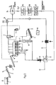
- ein Ablaufschema, in welchem die einzelnen Vorrichtungen zur Durchführung des Reingungsverfahrens schematisch dargestellt sind;
- Fig. 2
- ein Ablaufschema für eine alternative Ausführungsform;
- Fig. 3
- eine schematische Darstellung eines Ausführungsbeispiels für eine Bedampfungseinheit und
- Fig. 4
- eine schematische Schnittdarstellung eines Seitenteils der Bedampfungseinheit gemäß Fig. 3
- Fig. 1
- a flow diagram in which the individual devices for performing the cleaning process are shown schematically;
- Fig. 2
- a flowchart for an alternative embodiment;
- Fig. 3
- a schematic representation of an embodiment for a vapor deposition unit and
- Fig. 4
- 3 shows a schematic sectional illustration of a side part of the vapor deposition unit according to FIG. 3
Die Bedampfungsvorrichtung besteht aus einem dampfdurchlässigen Förderband 5, welches über eine Zugangsschleuse 16 mit Material beschickt wird. Die Schichtdicke läßt sich durch die Vorschubsgeschwindigkeit des Bandes 5 regeln. Unterhalb des Bandes 5 ist ein weiteres Förderband angeordnet, mit welchem durch das Band 5 durchfallendes Feinmaterial aus der Bedampfungsvorrichtung heraus einem Elevator 15 zugeführt wird, mittels welchem das Material in den Kreislauf zurückgeführt wird. Im gezeigten Ausführungsbeispiel fördert der Elevator 15 das Feinmaterial zurück auf das Transportband 4. Nach erfolgter Behandlung wird das gereinigte Gut über eine Ausgangsschleuse 17 einem Transportband 6 zugeleitet, welches im gezeigten Ausführungsbeispiel ein Kühlband ist. Über einen Dampfabzug wird Restdampf abgezogen und ebenfalls in den Kreislauf zurückgeführt. Im Anschluß an das Kühlband wird das gereinigte Gut zur Wiederverwertung bereitgestellt.The steaming device consists of a vapor-
In einem Dampfkessel 7 wird Kesselspeisewasser mittels eines Brenners, welcher in einem Bereich von 1250°C arbeitet, bei einem Druck von vorzugsweise 1,5 bar auf etwa 145°C erwärmt. In einem Überhitzer 8 wird Dampf mit einer Temperatur von vorzugsweise 700°C erzeugt, welcher bei im wesentlichen gleichbleibenden Druck von zwischen 0,5 und 1,5 bar, einem Dampfverteiler zugeführt wird. Über den Dampfverteiler wird der Dampf in die Bedampfungsanlage 5 eingebracht und dort in den Bereich zwischen Obertrum und Untertrum des dampfdurchlässigen Förderbandes, die gesamte Fläche beaufschlagend, geführt. Somit wird sichergestellt, daß die auf dem Förderband befindliche Schicht von zu reinigendem Gut gleichmäßig von Dampf durchströmt wird. Bei diesem sogenannten Destillationsverfahren wird das Gut unter anderem vom KW, CKW, PAK, CI, S und Hg gereinigt. Dabei wird die Bedampfung über eine vorgegebene Zeitspanne fortgeführt. Da die Bedampfungsvorrichtung, auch als Destillationsreaktor zu bezeichnen, im wesentlich gasdicht ausgeführt ist, kann ein entsprechender Druck von beispielsweise 1,5 bar aufrechterhalten werden.In a
Der Dampf wird vom Destillationsreaktor über Leitungen einem Feinteile-Staub-Filter 9 zugeführt, in welchem die Brüden beispielsweise < 10 mg/Ncbm entstaubt werden. In einem Mischer 11 wird der Feinteilestaub granuliert, pelletiert, koaguliert oder dergleichen. So kann beispielsweise eine Mischung mit H₂O gegebenenfalls unter Zufügung von Bindern oder sonstigen Additiven erfolgen. Anschließend läßt sich das Mischungsprodukt wieder in den Kreislauf zurückführen, beispielsweise auf das Transportband 4. Die entstaubten Brüden werden einem Kondensator 10 zugeführt. Das Kondensat wird in einem Dreiphasenseparator 24 behandelt, in welchem Öle und Feststoffe (Schlamm) sowie Wasser voneinander getrennt werden. Die Öle und Feststoffe können entsorgt werden, während das Wasser nach einer weiteren Aufbereitung als Kesselspeisewasser im Kessel 7 zur Heißdampferzeugung verwendet wird und somit im Kreislauf verbleibt. Es wird darauf hingewiesen, daß anstelle des Dreiphasenseparators auch ein Purifikator mit nachgeschaltetem Clarifikator Verwendung finden kannThe steam is fed from the distillation reactor via lines to a fine
Zur Aufbereitung des separierten Wassers wird eine aus Ultrafiltration 25, Umkehrosmose 26 und thermischen Entgasung 27 bestehende Wasseraufbereitungsanlage verwendet, die salzfreies Speisewasser in Mischbettqualität erzeugt. Dies bedeutet als Richtwert eine Leitfähigkeit von 0,2µS/cm sowie weitestgehende Silikatfreiheit im Nachspeisewasser. Im Kesselwasser wird bis auf 50µS/cm aufgesalzt, so daß im Dampf ein Leitwert von 0,2µS/cm und ein Silikatgehalt von 0,02mg/l eingehalten werden. Die verwendete Aufbereitung mit Umkehrosmoseeinrichtung 26 stellt ein ideales Verfahren zur Einrichtung der angestrebten Wasserqualität dar.A water treatment system consisting of
Die vom Kondensator 10 mittels einer Vakuumpumpe abgesaugten Gase werden einem Adsorber 12 zugeführt. In diesem Adsorber, der beispielsweise eine Abluftreinigung mittels Aktivkohle durchführt, fallen flüchtige anorganische Bestandteile wie Schwefel, Chloride, Quecksilber, Arsen usw. an. Die flüchtigen organischen Stoffe werden nach Vermischung mit Frischluft im Brenner und der vorgeschalteten Brennkammer am Dampfkessel bei Temperaturen um 1200°C bzw. 1250°C voll ausgebrannt.The gases drawn off from the
Die Kaminabluft bedarf praktisch keiner besonderen Reinigungsverfahren.Chimney exhaust air requires practically no special cleaning processes.
Bei dem gezeigten Ausführungsbeispiel entstehen keine weiteren Abgase aus der Gesamtanlage. Als einzige Abfälle bzw. Reststoffe entstehen, abgesehen von der beladenen Aktivkohle im Adsorber 12, keine Rückstände, die nicht in konzentriertester Form ausgeschleust werden. Damit ist eine Minimierung der Abfallstoffe erreichbar.In the exemplary embodiment shown, no further exhaust gases arise from the overall system. The only waste or residues, apart from the loaded activated carbon in the
Bei dem in Fig. 2 gezeigten Ausführungsbeispiel handelt es sich um eine gegenüber der in Fig. 1 gezeigten Anlage modifizierten Anlage. Gleiche Elemente sind mit gleichen Bezugszeichen versehen. Im Zuführbereich wurde das Sieb 23 weggelassen, so daß das Magnetband 14 im Bereich des Transportbandes 2 gebildet ist. Auch wurde auf einen Elevator 15 verzichtet. Der wesentliche Unterschied gegenüber dem in Fig. 1 gezeigten Ausführungsbeispiel besteht darin, daß dem Destillationsreaktor 5 eine weitere Reaktorsäule 18 nachgeschaltet ist. In der Reaktorsäule, die im wesentlichen aus einem Reaktorgehäuse besteht, in dem ein Schadgasrohr angeordnet ist, findet eine Weiter- und/oder Nachbehandlung des zu reinigenden Gutes statt. Um das Schadgasrohr herum sind haubenartige Bleche angeordnet, so daß das zu reinigende Gut bis zum unten angeordneten Austrag über Bleche rieselt, während es im Gegenstrom von einem Behandlungsgut durchströmt wird. Dieses Gas sammelt sich mit den weiteren, dem zu reinigenden Gut entzogenen Stoffen, innerhalb der Hauben und wird über das Schadgasrohr abgeführt. Im übrigen entspricht die in Fig. 2 gezeigte Anlage vom Verfahrensablauf her der in Fig. 1 gezeigten Anlage.The exemplary embodiment shown in FIG. 2 is a modified system compared to the system shown in FIG. 1. The same elements are provided with the same reference symbols. In the feed area, the
In Fig. 3 ist ein Destillationsreaktor 5 schematisch dargestellt. Der Destillationsreaktor 5 ist im wesentlichem in einem gasdichten Gehäuse, vorzugsweise aus Edelstahl angeordnet. Auf der Beschickungsseite ist eine Eingangsschleuse 16, auf der Ausbringseite eine Ausgangsschleuse 17 ausgebildet. Innerhalb des Gehäuses ist ein Destillationsband 20 angeordnet, welches dampfdurchlässig ist. Dabei handelt es sich beispielsweise um ein gelochtes Edelstahlband bzw. ein Metallgitter. Ein Düsensystem 19, welches zwischen Obertrum und Untertrum des Bandes 20 angeordnet ist, sorgt für eine flächendeckende Durchdampfung der auf das Band 20 aufgebrachten Reinigungsgutschicht. Der Dampf verläßt das Gehäuse nach oben. Ein Teil des Bedampfungssystems ist schematisch vergrößert in Fig. 4 gezeigt. Der Dampf wird über eine Kanal 21 zwischen Obertrum und Untertrum des Bandes 20 von der Seite her zugeführt. Er durchströmt flächendeckend das Obertrum und die darauf aufgebrachte Schicht von zu reinigendem Gut und wird über einen Absaugkanal 22 wieder aus dem Gehäuse abgesaugt und der beschriebenen weiteren Behandlung zugeführt. Unterhalb des Bandes 20 kann ein Transportband zum Auffangen von durchfallenden Reiningungsstoffbestandteilen angeordnet sein. Die Feinbestandteile können wieder in den Reinigungskreislauf zurückgeführt werden. Die Behandlungszeit einer Schicht innerhalb des Destillationsreaktors kann bis zu 60 min betragen. Der Dampf hat vorzugsweise eine Temperatur von 700°C bei einem Vorlaufdruck von 0,5 und 1,5 bar.3, a
- 11
- KastenbeschickerBox feeder
- 22nd
- TransportbandConveyor belt
- 33rd
- BrecherCrusher
- 44th
- TransportbandConveyor belt
- 55
- Destillationsreaktor/BedampfungsvorrichtungDistillation reactor / steaming device
- 66
- TransportbandConveyor belt
- 77
- DampfkesselSteam boiler
- 88th
- ÜberhitzerSuperheater
- 99
- Filterfilter
- 1010th
- Kondensatorcapacitor
- 1111
- Mischermixer
- 1212th
- AdsorberAdsorber
- 1313
- SteueranlageControl system
- 1414
- MagnetbandMagnetic tape
- 1515
- ElevatorElevator
- 1616
- ZuführschleuseFeed lock
- 1717th
- AusbringschleuseSpreading lock
- 1818th
- ReaktorsäuleReactor column
- 1919th
- DampfdüsenSteam nozzles
- 2020th
- DestillationsbandDistillation belt
- 2121
- ZuführkanalFeed channel
- 2222
- AbsaugkanalSuction channel
- 2323
- SiebSieve
- 2424th
- 3-Phasenseparator3-phase separator
- 2525th
- UltrafiltrationUltrafiltration
- 2626
- UmkehrosmoseReverse osmosis
- 2727
- Thermische EntgasungThermal degassing
Claims (14)
dadurch gekennzeichnet,
daß das Behandlungsgut auf einer gasdurchlässigen, kontinuierlich oder schrittweise vorwärts von einer Aufgabezone zu einer Entnahmezone bewegten Unterlage flächig in einer vorgegebenen Schichtstärke ausgebreitet wird, daß durch die Schicht des Behandlungsgutes ausschließlich Heißdampf mit einer Temperatur ≧ 700°C und einem Dampfdruck zwischen 0,5 und 1,5 bar derart hindurchgeführt wird, daß durch die die Heißdampfbehandlung überlagernde Bewegung des Behandlungsgutes dieses in der Aufgabezone zunächst getrocknet wird und sodann in der nachfolgenden Reaktionszone die Schadstoffe sukzessive mit ansteigender Temperatur des Behandlungsgutes über ihren Siedepunkt erhitzt, verdampft und mit den Heißdampfbrüden abgeführt werden, und daß schließlich die Brüden in an sich bekannter Weise entstaubt und kondensiert werden, wobei das Kondensat in einem Drei-Phasen-Separator in feste Rückstandsprodukte, Öle und eine wässrige Phase getrennt wird, die nach einer Wasseraufbereitung als Kesselspeisewasser zur Heißdampferzeugung verwendet wird.Process for the thermal separation of organic and / or inorganic pollutants from contaminated material to be treated, such as soils, sludges, mill scale and the like, with hot gases, which are then dedusted, condensed and subjected to condensate cleaning,
characterized by
that the material to be treated is spread on a gas-permeable, continuously or step-wise moving surface from a feed zone to a removal zone in a predetermined layer thickness that only hot steam with a temperature of ≧ 700 ° C and a steam pressure between 0.5 and 1.5 bar is passed in such a way that the movement of the material to be treated, which is superimposed on the hot steam treatment, first dries it in the feed zone and then, in the subsequent reaction zone, the pollutants are gradually heated above their boiling point with increasing temperature of the material to be treated, evaporated and discharged with the steam , and that finally the vapors are dedusted and condensed in a manner known per se, the condensate being separated in a three-phase separator into solid residue products, oils and an aqueous phase which are after a water conditioner line is used as boiler feed water for the production of superheated steam.
Priority Applications (1)
| Application Number | Priority Date | Filing Date | Title |
|---|---|---|---|
| EP94116974A EP0715902A1 (en) | 1994-10-27 | 1994-10-27 | Method and plant for the thermal separation of pollutants from contaminated matter |
Applications Claiming Priority (1)
| Application Number | Priority Date | Filing Date | Title |
|---|---|---|---|
| EP94116974A EP0715902A1 (en) | 1994-10-27 | 1994-10-27 | Method and plant for the thermal separation of pollutants from contaminated matter |
Publications (1)
| Publication Number | Publication Date |
|---|---|
| EP0715902A1 true EP0715902A1 (en) | 1996-06-12 |
Family
ID=8216414
Family Applications (1)
| Application Number | Title | Priority Date | Filing Date |
|---|---|---|---|
| EP94116974A Withdrawn EP0715902A1 (en) | 1994-10-27 | 1994-10-27 | Method and plant for the thermal separation of pollutants from contaminated matter |
Country Status (1)
| Country | Link |
|---|---|
| EP (1) | EP0715902A1 (en) |
Cited By (6)
| Publication number | Priority date | Publication date | Assignee | Title |
|---|---|---|---|---|
| WO1999003609A1 (en) * | 1997-07-18 | 1999-01-28 | Mellin, Monica | A process for separating a contaminating substance from a material contaminated by said substance |
| DE10160566B4 (en) * | 2001-02-12 | 2010-04-22 | Parsons Corp., Pasadena | Improved process for incineration-free decontamination of materials containing hazardous components |
| US8257461B2 (en) | 2007-04-19 | 2012-09-04 | Savaterra Oy | Method of producing fertilizer out of sludge |
| DE102013211252A1 (en) | 2013-06-17 | 2014-12-31 | Robert Bosch Gmbh | Plant and process for the treatment of contaminated waste water |
| CN110986065A (en) * | 2019-11-18 | 2020-04-10 | 国网河北省电力有限公司电力科学研究院 | System for heating smoke by cooling air of slag drying machine and method for eliminating smoke plume |
| CN113426820A (en) * | 2021-08-02 | 2021-09-24 | 安徽省通源环境节能股份有限公司 | Direct thermal desorption device of overheated formula steam |
Citations (4)
| Publication number | Priority date | Publication date | Assignee | Title |
|---|---|---|---|---|
| EP0405067A2 (en) * | 1989-06-30 | 1991-01-02 | LEONHARD WEISS GmbH & Co. NIEDERLASSUNG CRAILSHEIM | Device for removing volatile contaminants from soil or similar |
| EP0432812A1 (en) * | 1989-11-15 | 1991-06-19 | METALLGESELLSCHAFT Aktiengesellschaft | Method for cleaning contaminated soil |
| EP0469443A2 (en) * | 1990-07-30 | 1992-02-05 | HEINRICH DERNBACH GmbH, ÖKOLOGISCH-LANDSCHAFTSBEZOGENE SYSTEMBERATUNG | Method of treating waste |
| DE4303722C1 (en) * | 1993-02-10 | 1994-05-05 | Metallgesellschaft Ag | Decontamination of soil, sand, sludge or solid aggregate or residue - by heating with recycled hot gas or super-heated steam contg. oxidant, removing dust, condensing impurities and chemical or physical removal |
-
1994
- 1994-10-27 EP EP94116974A patent/EP0715902A1/en not_active Withdrawn
Patent Citations (4)
| Publication number | Priority date | Publication date | Assignee | Title |
|---|---|---|---|---|
| EP0405067A2 (en) * | 1989-06-30 | 1991-01-02 | LEONHARD WEISS GmbH & Co. NIEDERLASSUNG CRAILSHEIM | Device for removing volatile contaminants from soil or similar |
| EP0432812A1 (en) * | 1989-11-15 | 1991-06-19 | METALLGESELLSCHAFT Aktiengesellschaft | Method for cleaning contaminated soil |
| EP0469443A2 (en) * | 1990-07-30 | 1992-02-05 | HEINRICH DERNBACH GmbH, ÖKOLOGISCH-LANDSCHAFTSBEZOGENE SYSTEMBERATUNG | Method of treating waste |
| DE4303722C1 (en) * | 1993-02-10 | 1994-05-05 | Metallgesellschaft Ag | Decontamination of soil, sand, sludge or solid aggregate or residue - by heating with recycled hot gas or super-heated steam contg. oxidant, removing dust, condensing impurities and chemical or physical removal |
Cited By (8)
| Publication number | Priority date | Publication date | Assignee | Title |
|---|---|---|---|---|
| WO1999003609A1 (en) * | 1997-07-18 | 1999-01-28 | Mellin, Monica | A process for separating a contaminating substance from a material contaminated by said substance |
| DE10160566B4 (en) * | 2001-02-12 | 2010-04-22 | Parsons Corp., Pasadena | Improved process for incineration-free decontamination of materials containing hazardous components |
| US8257461B2 (en) | 2007-04-19 | 2012-09-04 | Savaterra Oy | Method of producing fertilizer out of sludge |
| DE102013211252A1 (en) | 2013-06-17 | 2014-12-31 | Robert Bosch Gmbh | Plant and process for the treatment of contaminated waste water |
| US10112849B2 (en) | 2013-06-17 | 2018-10-30 | Robert Bosch Gmbh | System and method for treating contaminated wastewater |
| CN110986065A (en) * | 2019-11-18 | 2020-04-10 | 国网河北省电力有限公司电力科学研究院 | System for heating smoke by cooling air of slag drying machine and method for eliminating smoke plume |
| CN110986065B (en) * | 2019-11-18 | 2021-08-17 | 国网河北省电力有限公司电力科学研究院 | System for heating smoke by cooling air of slag drying machine and method for eliminating smoke plume |
| CN113426820A (en) * | 2021-08-02 | 2021-09-24 | 安徽省通源环境节能股份有限公司 | Direct thermal desorption device of overheated formula steam |
Similar Documents
| Publication | Publication Date | Title |
|---|---|---|
| DE69131623T2 (en) | METHOD FOR DISINFECTING CONTAMINATED SOIL | |
| DE3706684C2 (en) | ||
| EP1289893B1 (en) | Device and method for treating a refuse material containing hydrocarbons | |
| DE344946T1 (en) | METHOD AND DEVICE FOR TREATING LACQUER SLUDGE. | |
| EP0432812B1 (en) | Method for cleaning contaminated soil | |
| DE4112593A1 (en) | METHOD AND SYSTEM FOR THERMALLY TREATING WASTE POLLUTED WITH ORGANIC COMPONENTS, IN PARTICULAR METAL SCRAP | |
| WO1990012756A1 (en) | Process and device for treating brines and contaminated mineral salts or mixtures thereof | |
| DE2422814A1 (en) | PROCEDURE AND SYSTEM FOR CLEANING UP CONTAMINATED LIQUIDS | |
| DE69218177T2 (en) | METHOD AND DEVICE FOR TREATING EXHAUST GAS | |
| DE3902611C2 (en) | Method and device for deodorising and cleaning wet gases resulting from the combustion of wet waste sludge at a moderate temperature | |
| EP0715902A1 (en) | Method and plant for the thermal separation of pollutants from contaminated matter | |
| DE3612259A1 (en) | SOLVENT ELIMINATION METHOD FOR PURIFYING AIR FROM SOLVENT DAMPERS | |
| DE69615077T2 (en) | Method and device for removing organic halogenated molecules from gas streams | |
| EP0701491B1 (en) | Device and process for cleansing polluted ground | |
| EP0498017B1 (en) | Process for removing pollutants from contaminated material, more particularly from contaminated soil and rubble | |
| DE3023670C2 (en) | Method and device for smoldering oil shale | |
| DE19715839B4 (en) | Process and device for cleaning oil and water-containing mill scale sludges | |
| WO1993018866A1 (en) | Soil decontaminating process | |
| EP0341580B1 (en) | Process for purifying by distillation mercury-containing materials or mixed materials | |
| DE69204420T2 (en) | Process for removing pollutants from substrate drying gas. | |
| DE1257117B (en) | Device for achieving chemical or physical effects between a pourable solid and at least one flowable medium | |
| DE69817588T2 (en) | TREATMENT OF POLLUTED FLOORS | |
| DE2606272C3 (en) | Process for removing the moisture and fat content of a rolling mill sludge | |
| EP0509315B1 (en) | Process and apparatus for treatment and disposal of solid pollutants | |
| DE2715607A1 (en) | METHOD AND DEVICE FOR TREATING A POLLUTED EXHAUST GAS |
Legal Events
| Date | Code | Title | Description |
|---|---|---|---|
| PUAI | Public reference made under article 153(3) epc to a published international application that has entered the european phase |
Free format text: ORIGINAL CODE: 0009012 |
|
| 17P | Request for examination filed |
Effective date: 19950519 |
|
| AK | Designated contracting states |
Kind code of ref document: A1 Designated state(s): AT BE DE ES FR IT LU NL |
|
| STAA | Information on the status of an ep patent application or granted ep patent |
Free format text: STATUS: THE APPLICATION HAS BEEN WITHDRAWN |
|
| 18W | Application withdrawn |
Withdrawal date: 19960531 |