EP0404699B1 - Einfacher oder doppelter Tragarm für Rastschienen zum Stützen von Regalen und Möbelelementen - Google Patents
Einfacher oder doppelter Tragarm für Rastschienen zum Stützen von Regalen und Möbelelementen Download PDFInfo
- Publication number
- EP0404699B1 EP0404699B1 EP90420293A EP90420293A EP0404699B1 EP 0404699 B1 EP0404699 B1 EP 0404699B1 EP 90420293 A EP90420293 A EP 90420293A EP 90420293 A EP90420293 A EP 90420293A EP 0404699 B1 EP0404699 B1 EP 0404699B1
- Authority
- EP
- European Patent Office
- Prior art keywords
- bracket
- rack
- tabs
- slot
- pitch
- Prior art date
- Legal status (The legal status is an assumption and is not a legal conclusion. Google has not performed a legal analysis and makes no representation as to the accuracy of the status listed.)
- Expired - Lifetime
Links
Images

Classifications
-
- A—HUMAN NECESSITIES
- A47—FURNITURE; DOMESTIC ARTICLES OR APPLIANCES; COFFEE MILLS; SPICE MILLS; SUCTION CLEANERS IN GENERAL
- A47B—TABLES; DESKS; OFFICE FURNITURE; CABINETS; DRAWERS; GENERAL DETAILS OF FURNITURE
- A47B57/00—Cabinets, racks or shelf units, characterised by features for adjusting shelves or partitions
- A47B57/30—Cabinets, racks or shelf units, characterised by features for adjusting shelves or partitions with means for adjusting the height of detachable shelf supports
- A47B57/40—Cabinets, racks or shelf units, characterised by features for adjusting shelves or partitions with means for adjusting the height of detachable shelf supports consisting of hooks coacting with openings
- A47B57/42—Cabinets, racks or shelf units, characterised by features for adjusting shelves or partitions with means for adjusting the height of detachable shelf supports consisting of hooks coacting with openings the shelf supports being cantilever brackets
- A47B57/425—Cabinets, racks or shelf units, characterised by features for adjusting shelves or partitions with means for adjusting the height of detachable shelf supports consisting of hooks coacting with openings the shelf supports being cantilever brackets introduced by a vertical pivoting movement
Definitions
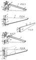
- the subject of the invention is a simple or double improved console for a rack for supporting shelving and furnishing elements.
- shelving supports are produced using generally U-shaped metal profiles (1), provided on their front face with a plurality of oblong slots (1-1) in the lengthwise direction equidistantly arranged in groups. of two or individually and authorizing the positioning, the hanging and the suspension of single or double profiled brackets (2) arranged with hooking lugs (2-1).
- said consoles have two walls or sides (2-2) parallel and arranged at the rear in their upper part with a first pair of legs (2-1) and in their part lower with a couple of underlying legs (2-3).
- consoles are designed specifically for a type of rack, so that in practice, it is necessary to manufacture for each rack a suitable console. More specifically and by way of example, there are currently commercial racks whose spacing of the slots according to a determined pitch is 32 millimeters (dimension c), or racks with a pitch of 50 millimeters (dimension c1). The spacing of the fastening tabs is therefore adapted to these dimensions. The disadvantage therefore results in an increase in the number of manufactured parts and therefore in non-negligible storage costs. In addition, we do not always have consoles of a specific size with regard to racks. This also poses problems practical, including, for example, doubling console stocks to meet demand.
- a rack arranged with a plurality of vertical slots of different lengths allowing the positioning of the console hooks.
- the brackets are positioned by their hooks in the bottom of the slots and are limited to supports given on the bottom face of the slots according to preset spacing dimensions.
- the aim of the research according to the invention was to remedy these drawbacks by proposing a simple solution which is practical to implement.
- the console is remarkable in that the upper and lower legs of each wall are judiciously arranged and spaced from one another to allow universal use of the console regardless of the spacing characteristics of the slots successive lengthwise established on a range of known support racks, the spacing of said legs being different from the pitch defined between two successive slots formed on a rack in which the spacing pitch of the slots is the most important and in that the arrangement of the legs is such that the console can be positioned on the bottom of the successive slots of the rack whose pitch is the most reduced, and on the other hand and respectively on the bottom of the upper slot and the top of the underlying slot for the rack whose pitch is greater than the previous one.
- the upper edge of the lower hooking tab is substantially in contact with the top of the slot ensuring the hooking and the lower positioning of the console.
- the lower tab is arranged on its upper edge with a profiled shape forming a projection defining a groove at the rear and ensuring engagement of the console by clipping to its lower part.
- the console (5) comprises a sidewall (5-1) and more generally two parallel sidewalls (5-2), profiled, capable of serving as support for shelving and the like.
- the console In its rear part, the console has on each side two profiled legs (5-3) (5-4) capable of engaging in the slots established on the racks (3) (4).
- said legs are judiciously disposed and spaced from one another to allow universal use of the corresponding console whatever the characteristics of the support rack. To this end, the spacing of the legs no longer corresponds to the pitch of the successive slots of a rack of which the spacing pitch of the slots is the largest.
- the arrangement of the legs (5-3) (5-4) is such that the console according to the invention can be positioned by resting on the bottom (3-2) (6-2) of the slots (3-1) ( 4-1) successive of the rack whose pitch is 32 millimeters and respectively on the bottom (4-2) of the upper slot and the top (4-3) of the underlying slot for the rack whose pitch is 50 millimeters.
- the upper edge (5-5) of the lower tab (5-4) comes into substantial contact or contact with the top (4-3) of the slot ensuring the attachment and the lower positioning of the console.
- At least one of the lower legs (5-4) is arranged on its upper edge (5-5) with a profiled shape (5-6) forming a projection or boss substantially raised to define the back of a groove (5-7).
- This projection makes it possible to introduce and fix the console by clipping to its lower part. In this case, the console is held securely and any angular movement thereof is avoided.
- connection line between the high and low legs with oblique sections capable of coming to bear on the front face of the rack.
- console Only one type of console can be made, making it practical to use and considerably limiting stocks.
Landscapes
- Assembled Shelves (AREA)
- Warehouses Or Storage Devices (AREA)
- Display Racks (AREA)
- Cabinets, Racks, Or The Like Of Rigid Construction (AREA)
Claims (3)
- Weiterentwickelte Konsole für Regal- und Möblierungselemente-Wandschiene mit mindestens einer Wandung oder einer Flanke mit einer Ober- und einer Unter-Halterung zur Aufhängung und zur Positionierung in den mit gleichen Abständen in der Längsrichtung an einer Wandschiene befindlichen, aufeinanderfolgenden Spalten, wobei die unteren und oberen Halterungen jeder Wandung so angeordnet sind und einen derartigen Abstand voneinander haben, daß die Konsole auf dem Grund der aufeinanderfolgenden Spalte der Wandschiene positioniert werden kann, wobei besagte Konsole dadurch gekennzeichnet ist, daß die oberen (5-3) und unteren (5-4) Halterungen jeder Wandung zweckmäßig angeordnet sind und untereinander einen derartigen Abstand aufweisen, daß eine universelle Verwendung der Konsole ermöglicht wird - gleich welche Abstandsmerkmale die aufeinanderfolgenden Spalte auf einer Wandschienen-Reihe aufweisen -, dabei ist der Abstand der besagten Halterungen (5-3) (5-4) verschieden von der definierten Teilung zwischen zwei aufeinanderfolgenden Spalten, die auf einer Wandschiene ausgebildet sind, deren Abstandsteilung die bedeutendste ist, und dadurch daß die Anordnung der Halterungen (5-3) (5-4) derart gestaltet ist, daß die Konsole auf dem Grund (3-2) (4-2) der aufeinanderfolgenden Spalten (3-1) (4-1) der Wandschiene positioniert werden kann, deren Teilung die geringste ist, und andererseits und jeweils auf dem Grund (4-2) des oberen Spalts und dem Oberteil (4-3) des darunterliegenden Spalts für die Wandschiene, deren Teilung größer als die vorhergehende ist.
- Konsole nach Anspruch 1, dadurch gekennzeichnet, daß die Oberkante (5-5) der unteren Aufhängehalterung wesentlich mit dem Oberteil des Spalts (4-3) in Verbindung steht, wodurch die Aufhängung und die untere Positionierung der Konsole sichergestellt wird.
- Konsole nach den Ansprüchen 1 und 2 zusammen, dadurch gekennzeichnet, daß die untere Halterung (5-4) auf ihrer Oberkante mit einer vorspringenden Profilform (5-6) ausgestattet ist, die an der Rückseite eine Auskehlung (5-7) bildet, und eine Verbindung der Konsole durch Einklipsen an ihrem Unterteil gewährleistet.
Priority Applications (1)
| Application Number | Priority Date | Filing Date | Title |
|---|---|---|---|
| AT90420293T ATE96985T1 (de) | 1989-06-23 | 1990-06-22 | Einfacher oder doppelter tragarm fuer rastschienen zum stuetzen von regalen und moebelelementen. |
Applications Claiming Priority (2)
| Application Number | Priority Date | Filing Date | Title |
|---|---|---|---|
| FR8908741 | 1989-06-23 | ||
| FR8908741A FR2648689B1 (fr) | 1989-06-23 | 1989-06-23 | Console simple ou double perfectionnee pour cremaillere support de rayonnages et d'elements d'ameublement |
Publications (2)
| Publication Number | Publication Date |
|---|---|
| EP0404699A1 EP0404699A1 (de) | 1990-12-27 |
| EP0404699B1 true EP0404699B1 (de) | 1993-11-10 |
Family
ID=9383289
Family Applications (1)
| Application Number | Title | Priority Date | Filing Date |
|---|---|---|---|
| EP90420293A Expired - Lifetime EP0404699B1 (de) | 1989-06-23 | 1990-06-22 | Einfacher oder doppelter Tragarm für Rastschienen zum Stützen von Regalen und Möbelelementen |
Country Status (5)
| Country | Link |
|---|---|
| EP (1) | EP0404699B1 (de) |
| AT (1) | ATE96985T1 (de) |
| DE (1) | DE69004497T2 (de) |
| ES (1) | ES2045869T3 (de) |
| FR (1) | FR2648689B1 (de) |
Families Citing this family (2)
| Publication number | Priority date | Publication date | Assignee | Title |
|---|---|---|---|---|
| DE29717791U1 (de) * | 1997-10-06 | 1999-02-04 | Tegometall (International) AG, Tägerwilen | Regalkonsole |
| RU2245092C2 (ru) * | 2003-01-08 | 2005-01-27 | Зао "Борторгтехмаш" | Соединение полок торгово-выставочного оборудования стеллажного типа |
Family Cites Families (3)
| Publication number | Priority date | Publication date | Assignee | Title |
|---|---|---|---|---|
| DE1177781B (de) * | 1956-02-27 | 1964-09-10 | Harry Olofsson | Regal mit hoehenstellbaren Fachbodentraegern |
| FR1380062A (fr) * | 1964-01-11 | 1964-11-27 | Tim Fleck Sa | Dispositif de réglage, pour ossature métallique notamment pour supports d'étagères ou autres applications |
| US3482706A (en) * | 1966-09-29 | 1969-12-09 | Eric C Stewart | Panelling arrangement for supporting shelves and other fitments |
-
1989
- 1989-06-23 FR FR8908741A patent/FR2648689B1/fr not_active Expired - Fee Related
-
1990
- 1990-06-22 EP EP90420293A patent/EP0404699B1/de not_active Expired - Lifetime
- 1990-06-22 AT AT90420293T patent/ATE96985T1/de not_active IP Right Cessation
- 1990-06-22 DE DE90420293T patent/DE69004497T2/de not_active Expired - Fee Related
- 1990-06-22 ES ES90420293T patent/ES2045869T3/es not_active Expired - Lifetime
Also Published As
| Publication number | Publication date |
|---|---|
| DE69004497D1 (de) | 1993-12-16 |
| DE69004497T2 (de) | 1994-02-24 |
| ES2045869T3 (es) | 1994-01-16 |
| FR2648689A1 (fr) | 1990-12-28 |
| ATE96985T1 (de) | 1993-11-15 |
| EP0404699A1 (de) | 1990-12-27 |
| FR2648689B1 (fr) | 1994-05-20 |
Similar Documents
| Publication | Publication Date | Title |
|---|---|---|
| FR2458254A1 (fr) | Vitrine d'exposition adaptable en forme de caisson en verre | |
| CA1050489A (fr) | Dispositif d'assemblage entre montants et traverses pour l'execution de structures metalliques | |
| EP2808964A1 (de) | System, das als waagrechte Halterung für einen Gegenstand wie einen Kabelkanal dienen soll, und Schiene für ein solches System | |
| EP0085630A1 (de) | Trennwand bestehend aus auf einem Skelett befestigten Platten, sowie Platte für eine derartige Trennwand | |
| EP0404699B1 (de) | Einfacher oder doppelter Tragarm für Rastschienen zum Stützen von Regalen und Möbelelementen | |
| EP0468869A1 (de) | Platte für elektrisches Gerät und dazu gehörende Haltevorrichtung | |
| EP0813012B1 (de) | Elektrischer Kabelträger und Kabelrinne mit solchen Trägern | |
| EP0123614A1 (de) | Kartei mit schrägen Ablageflächen | |
| EP1013197B1 (de) | Regale | |
| BE1008651A3 (fr) | Rampe d'eclairage comportant un support d'etiquette de prix. | |
| CA2075561C (fr) | Element pour l'assemblage de pieces en bois | |
| FR2501984A1 (de) | ||
| EP2177775B1 (de) | Anlage zum Zusammenbauen von zwei Teilen, wie beispielsweise zwei Platten, mittels einer Schraubvorrichtung mit Verankerungsmutter | |
| BE890361A (fr) | Meuble | |
| FR2591453A1 (fr) | Casier, en particulier pour le rangement de bouteilles | |
| BE1004567A6 (fr) | Element de fixation pour gril de plafond ouvert. | |
| FR2502921A1 (fr) | Dispositif de rayonnage | |
| EP1358820A2 (de) | Träger für Regal, bestehend aus einem solchen Träger | |
| KR0132565Y1 (ko) | 밧테리 고정장치 | |
| FR2632838A1 (fr) | Dispositif de fixation d'un evier sur un meuble | |
| EP0997592A1 (de) | Abnehmbare Abdeckleiste | |
| FR2616822A1 (fr) | Dispositif de fixation d'un panneau sur des montants | |
| FR2700369A1 (fr) | Dispositif de fixation pour appareil mural, notamment pour appareil de chauffage électrique. | |
| FR2544183A3 (fr) | Rayonnage de stockage | |
| FR2735072A1 (fr) | Profile-support pour classeurs suspendus et analogues |
Legal Events
| Date | Code | Title | Description |
|---|---|---|---|
| PUAI | Public reference made under article 153(3) epc to a published international application that has entered the european phase |
Free format text: ORIGINAL CODE: 0009012 |
|
| AK | Designated contracting states |
Kind code of ref document: A1 Designated state(s): AT BE CH DE DK ES GB GR IT LI LU NL SE |
|
| 17P | Request for examination filed |
Effective date: 19910122 |
|
| 17Q | First examination report despatched |
Effective date: 19920714 |
|
| GRAA | (expected) grant |
Free format text: ORIGINAL CODE: 0009210 |
|
| AK | Designated contracting states |
Kind code of ref document: B1 Designated state(s): AT BE CH DE DK ES GB GR IT LI LU NL SE |
|
| PG25 | Lapsed in a contracting state [announced via postgrant information from national office to epo] |
Ref country code: DK Effective date: 19931110 |
|
| REF | Corresponds to: |
Ref document number: 96985 Country of ref document: AT Date of ref document: 19931115 Kind code of ref document: T |
|
| GBT | Gb: translation of ep patent filed (gb section 77(6)(a)/1977) |
Effective date: 19931112 |
|
| REF | Corresponds to: |
Ref document number: 69004497 Country of ref document: DE Date of ref document: 19931216 |
|
| ITF | It: translation for a ep patent filed | ||
| REG | Reference to a national code |
Ref country code: ES Ref legal event code: FG2A Ref document number: 2045869 Country of ref document: ES Kind code of ref document: T3 |
|
| REG | Reference to a national code |
Ref country code: GR Ref legal event code: FG4A Free format text: 3010175 |
|
| PG25 | Lapsed in a contracting state [announced via postgrant information from national office to epo] |
Ref country code: LU Free format text: LAPSE BECAUSE OF NON-PAYMENT OF DUE FEES Effective date: 19940630 Ref country code: LI Effective date: 19940630 Ref country code: CH Effective date: 19940630 |
|
| PLBE | No opposition filed within time limit |
Free format text: ORIGINAL CODE: 0009261 |
|
| STAA | Information on the status of an ep patent application or granted ep patent |
Free format text: STATUS: NO OPPOSITION FILED WITHIN TIME LIMIT |
|
| 26N | No opposition filed | ||
| EAL | Se: european patent in force in sweden |
Ref document number: 90420293.4 |
|
| REG | Reference to a national code |
Ref country code: CH Ref legal event code: PL |
|
| PGFP | Annual fee paid to national office [announced via postgrant information from national office to epo] |
Ref country code: AT Payment date: 19960528 Year of fee payment: 7 |
|
| PGFP | Annual fee paid to national office [announced via postgrant information from national office to epo] |
Ref country code: NL Payment date: 19960529 Year of fee payment: 7 |
|
| PGFP | Annual fee paid to national office [announced via postgrant information from national office to epo] |
Ref country code: GR Payment date: 19960531 Year of fee payment: 7 |
|
| PGFP | Annual fee paid to national office [announced via postgrant information from national office to epo] |
Ref country code: ES Payment date: 19960613 Year of fee payment: 7 |
|
| PGFP | Annual fee paid to national office [announced via postgrant information from national office to epo] |
Ref country code: BE Payment date: 19960710 Year of fee payment: 7 |
|
| PG25 | Lapsed in a contracting state [announced via postgrant information from national office to epo] |
Ref country code: AT Effective date: 19970622 |
|
| PG25 | Lapsed in a contracting state [announced via postgrant information from national office to epo] |
Ref country code: ES Free format text: LAPSE BECAUSE OF NON-PAYMENT OF DUE FEES Effective date: 19970623 |
|
| PG25 | Lapsed in a contracting state [announced via postgrant information from national office to epo] |
Ref country code: GR Free format text: LAPSE BECAUSE OF NON-PAYMENT OF DUE FEES Effective date: 19970630 Ref country code: BE Effective date: 19970630 |
|
| BERE | Be: lapsed |
Owner name: ETS G. GUILLAUMOND S.A. Effective date: 19970630 |
|
| PG25 | Lapsed in a contracting state [announced via postgrant information from national office to epo] |
Ref country code: NL Effective date: 19980101 |
|
| NLV4 | Nl: lapsed or anulled due to non-payment of the annual fee |
Effective date: 19980101 |
|
| PGFP | Annual fee paid to national office [announced via postgrant information from national office to epo] |
Ref country code: GB Payment date: 19980616 Year of fee payment: 9 |
|
| PGFP | Annual fee paid to national office [announced via postgrant information from national office to epo] |
Ref country code: SE Payment date: 19980617 Year of fee payment: 9 Ref country code: DE Payment date: 19980617 Year of fee payment: 9 |
|
| PG25 | Lapsed in a contracting state [announced via postgrant information from national office to epo] |
Ref country code: GB Free format text: LAPSE BECAUSE OF NON-PAYMENT OF DUE FEES Effective date: 19990622 |
|
| PG25 | Lapsed in a contracting state [announced via postgrant information from national office to epo] |
Ref country code: SE Free format text: THE PATENT HAS BEEN ANNULLED BY A DECISION OF A NATIONAL AUTHORITY Effective date: 19990629 |
|
| GBPC | Gb: european patent ceased through non-payment of renewal fee |
Effective date: 19990622 |
|
| EUG | Se: european patent has lapsed |
Ref document number: 90420293.4 |
|
| PG25 | Lapsed in a contracting state [announced via postgrant information from national office to epo] |
Ref country code: DE Free format text: LAPSE BECAUSE OF NON-PAYMENT OF DUE FEES Effective date: 20000503 |
|
| REG | Reference to a national code |
Ref country code: ES Ref legal event code: FD2A Effective date: 20000503 |
|
| PG25 | Lapsed in a contracting state [announced via postgrant information from national office to epo] |
Ref country code: IT Free format text: LAPSE BECAUSE OF NON-PAYMENT OF DUE FEES;WARNING: LAPSES OF ITALIAN PATENTS WITH EFFECTIVE DATE BEFORE 2007 MAY HAVE OCCURRED AT ANY TIME BEFORE 2007. THE CORRECT EFFECTIVE DATE MAY BE DIFFERENT FROM THE ONE RECORDED. Effective date: 20050622 |