EP0404152B1 - Lichtverstärker mit optischer Faser - Google Patents
Lichtverstärker mit optischer Faser Download PDFInfo
- Publication number
- EP0404152B1 EP0404152B1 EP90111762A EP90111762A EP0404152B1 EP 0404152 B1 EP0404152 B1 EP 0404152B1 EP 90111762 A EP90111762 A EP 90111762A EP 90111762 A EP90111762 A EP 90111762A EP 0404152 B1 EP0404152 B1 EP 0404152B1
- Authority
- EP
- European Patent Office
- Prior art keywords
- fiber
- demultiplexer
- optical multiplexer
- doped
- optical
- Prior art date
- Legal status (The legal status is an assumption and is not a legal conclusion. Google has not performed a legal analysis and makes no representation as to the accuracy of the status listed.)
- Expired - Lifetime
Links
Images


Classifications
-
- G—PHYSICS
- G02—OPTICS
- G02B—OPTICAL ELEMENTS, SYSTEMS OR APPARATUS
- G02B6/00—Light guides; Structural details of arrangements comprising light guides and other optical elements, e.g. couplings
- G02B6/24—Coupling light guides
- G02B6/255—Splicing of light guides, e.g. by fusion or bonding
- G02B6/2551—Splicing of light guides, e.g. by fusion or bonding using thermal methods, e.g. fusion welding by arc discharge, laser beam, plasma torch
-
- G—PHYSICS
- G02—OPTICS
- G02B—OPTICAL ELEMENTS, SYSTEMS OR APPARATUS
- G02B6/00—Light guides; Structural details of arrangements comprising light guides and other optical elements, e.g. couplings
- G02B6/24—Coupling light guides
- G02B6/26—Optical coupling means
- G02B6/28—Optical coupling means having data bus means, i.e. plural waveguides interconnected and providing an inherently bidirectional system by mixing and splitting signals
- G02B6/2804—Optical coupling means having data bus means, i.e. plural waveguides interconnected and providing an inherently bidirectional system by mixing and splitting signals forming multipart couplers without wavelength selective elements, e.g. "T" couplers, star couplers
- G02B6/2821—Optical coupling means having data bus means, i.e. plural waveguides interconnected and providing an inherently bidirectional system by mixing and splitting signals forming multipart couplers without wavelength selective elements, e.g. "T" couplers, star couplers using lateral coupling between contiguous fibres to split or combine optical signals
- G02B6/2835—Optical coupling means having data bus means, i.e. plural waveguides interconnected and providing an inherently bidirectional system by mixing and splitting signals forming multipart couplers without wavelength selective elements, e.g. "T" couplers, star couplers using lateral coupling between contiguous fibres to split or combine optical signals formed or shaped by thermal treatment, e.g. couplers
-
- H—ELECTRICITY
- H01—ELECTRIC ELEMENTS
- H01S—DEVICES USING THE PROCESS OF LIGHT AMPLIFICATION BY STIMULATED EMISSION OF RADIATION [LASER] TO AMPLIFY OR GENERATE LIGHT; DEVICES USING STIMULATED EMISSION OF ELECTROMAGNETIC RADIATION IN WAVE RANGES OTHER THAN OPTICAL
- H01S3/00—Lasers, i.e. devices using stimulated emission of electromagnetic radiation in the infrared, visible or ultraviolet wave range
- H01S3/09—Processes or apparatus for excitation, e.g. pumping
- H01S3/091—Processes or apparatus for excitation, e.g. pumping using optical pumping
- H01S3/094—Processes or apparatus for excitation, e.g. pumping using optical pumping by coherent light
- H01S3/094003—Processes or apparatus for excitation, e.g. pumping using optical pumping by coherent light the pumped medium being a fibre
-
- H—ELECTRICITY
- H01—ELECTRIC ELEMENTS
- H01S—DEVICES USING THE PROCESS OF LIGHT AMPLIFICATION BY STIMULATED EMISSION OF RADIATION [LASER] TO AMPLIFY OR GENERATE LIGHT; DEVICES USING STIMULATED EMISSION OF ELECTROMAGNETIC RADIATION IN WAVE RANGES OTHER THAN OPTICAL
- H01S3/00—Lasers, i.e. devices using stimulated emission of electromagnetic radiation in the infrared, visible or ultraviolet wave range
- H01S3/09—Processes or apparatus for excitation, e.g. pumping
- H01S3/091—Processes or apparatus for excitation, e.g. pumping using optical pumping
- H01S3/094—Processes or apparatus for excitation, e.g. pumping using optical pumping by coherent light
- H01S3/09408—Pump redundancy
Definitions
- This invention relates to an optical fiber samplifier wherein signal light and pumping light are introduced into a rare-earth element doped fiber doped with a rare-earth element to directly amplify the signal light.
- repeaters are interposed at predetermined intervals in order to compensate for attenuation of a light signal which may be caused from a loss of an optical fiber.
- a light signal is converted into an electric signal by means of a photodiode and then the electric signal is amplified by an electronic amplifier and then converted again into a light signal by means of a semiconductor laser or the like, whereafter the light signal thus obtained is forwarded again into the optical fiber transmission line. If such light signal can be directly amplified as it is with a low noise, then the optical repeaters can be reduced in size and economized.
- optical amplifiers which are objects of such researches are roughly classified into three types including (a) optical amplifiers wherein pumping light is combined with an optical fiber which is doped with a rare-earth element (Er, Nb, Yb or the like), (b) optical amplifiers which include a semiconductor laser doped with a rare-earth element, and (c) induction Raman amplifiers and induction Brillouin amplifiers which make use of a non-linear effect in an optical fiber.
- a rare-earth element Er, Nb, Yb or the like
- optical amplifiers which include a semiconductor laser doped with a rare-earth element
- induction Raman amplifiers and induction Brillouin amplifiers which make use of a non-linear effect in an optical fiber.
- the first optical amplifiers of (a) wherein pumping light is combined with a rare-earth element doped fiber have superior features that they have no polarization dependency, that noises are low and that the coupling loss of a transmission line is low.
- doped fiber a rare-earth element doped fiber
- FIG. 1 A principle of optical amplification in a doped fiber is illustrated in FIG. 1.
- an optical fiber 2 is constituted from a core 4 and a clad 6, and erbium (Er) is doped in the core 4.
- erbium Er
- pumping light is introduced into such erbium doped fiber 2
- erbium atoms are excited to a high energy level.
- signal light comes at the erbium atoms in the optical fiber 2 excited to a high energy level in this manner, the erbium atoms are changed into a ground state, whereupon stimulated emission of radiation of light occurs. Consequently, the power of the signal light is increased gradually along the optical fiber so that amplification of the signal light is effected.
- the optical fiber amplifier is generally denoted at 8 and includes an optical fiber 10 doped with erbium, an incidence side optical fiber 12, and an emergence side optical fiber 14.
- the incidence side optical fiber 12 and the doped fiber 10 are optically coupled to each other using a pair of lenses 16 while the doped fiber 10 and the emergence side optical fiber 14 are also optically coupled to each other using another pair of lenses 16.
- the optical fiber amplifier 8 further includes a pumping light source 18 such as a laser diode which emits pumping light of a wavelength of, for example, 1.48 ⁇ m.
- Pumping light emitted from the pumping light source 18 is coupled to signal light from the incidence side optical fiber 12 by means of an optical coupler 22 by way of a lens 20.
- the optical power of the pumping light is sufficiently high, erbium atoms in the doped fiber 10 are put into an excited state, and if signal light is introduced to the erbium atoms, then light is stimulated to emit from the erbium atoms. Consequently, the optical power of the signal light is increased gradually along the doped fiber 10, that is, the signal light is amplified, and the thus amplified signal light is introduced into the emergence side optical fiber 14.
- the pumping light source 18 is required to have a high power of such as, for example, several hundreds mW.
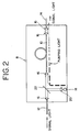
- a pair of pumping light sources 18 and 24 may be used as shown in FIG. 3.
- pumping light from the pumping light source 24 is optically coupled to pumping light from the pumping light source 18 by means of an optical coupler 28 by way of a lens 26.
- the pumping light coupled in this manner is then coupled to signal light from the incidence side optical fiber 12 by means of another optical coupler 22 and introduced into the doped optical fiber 10.
- a pumping light source of a high power of, for example, several hundreds mW or so is required as described above, and in order to make up for an insufficient power, normally a plurality of pumping light sources are used to introduce pumping light therefrom into the doped fiber. Consequently, in order to assure a high power of a pumping light source such as a laser diode, high driving current is required, which sometimes deteriorates the reliability of a device. Further, since a plurality of pumping light sources are used, an introducing mechanism for pumping light is complicated, which deteriorates the economy of the system. In addition, in case the output power of a pumping light source is low, the length of a doped fiber must be increased, for example, to several tens meters or so, and accordingly, there is a problem that miniaturization of the optical amplifier cannot be achieved.
- an object of the present invention to provide an optical fiber amplifier which solves such problems of the prior art as described above and makes effective use of pumping light.
- An optical fiber amplifier adapted to directly amplify signal light, comprising: a signal light transmission line including a rare-earth element doped fiber doped with a rare-earth element; a light source for emitting pumping light; a first optical multiplexer/demultiplexer interposed in said signal light transmission line and having an end connected to said light source; and pumping light reflecting means for returning pumping light which has been introduced into said doped fiber by way of said first optical multiplexer/demultiplexer and has passed through said doped fiber again into said doped fiber, said pumping light reflecting means transmitting signal light but reflecting pumping light.
- optical fiber amplifiers as set out in claims 6, 8 and 10.
- the amplification efficiency of the optical fiber amplifier is improved.
- Such improvement in amplification efficiency makes it possible to reduce the output power of the pumping light source and results in improvement in economy and reliability of the optical fiber samplifier. Meanwhile, if the output power of the pumping light source is the same, then the improvement in amplification efficiency makes it possible to reduce the length of the doped fiber to be used, and accordingly, miniaturization of the optical fiber amplifier can be achieved.
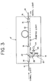
- the optical fiber amplifier shown is generally denoted at 30a and includes a rare-earth element doped fiber 10 having a core in which a rare-earth element such as erbium is doped.
- the optical fiber amplifier further includes an incidence side optical fiber 12 and an emergence side optical fiber 14.
- the doped fiber 10 and the emergence side optical fiber 14 are connected to each other by way of a connecting portion 32 provided by fusion joining or the like.
- the incidence side optical fiber 12 and the doped fiber 10 are connected to each other by way of a reflecting film 40.
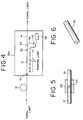
- connection at such reflecting film portion is constructed in such a manner as shown in an enlarged sectional view of FIG. 5.
- the reflecting film 40 is disposed in such a ferrule 42 as shown in FIG. 6, and the incidence side optical fiber 12 and the doped optical fiber 10 are inserted from the opposite ends into the ferrule 42 and connected to each other by way of the reflecting film 40 in such a manner as shown in FIG. 5.
- the inner diameter of the ferrule 42 is formed a little greater than the outer diameter of the optical fibers 10 and 12 such that, when the incidence side optical fiber 12 and the doped optical fiber 10 are inserted into the ferrule 42, the two optical fibers 10 and 12 may be secured in an accurately aligned condition with each other in and by the ferrule 42.
- the ferrule 42 is formed from such a material as, for example, a ceramics material.
- the reflecting film 40 has a characteristic that it reflects light of a wavelength of pumping light but transmits signal light of a 1.55 ⁇ m band therethrough and is formed from, for example, a dielectric multi layer film.
- an optical multiplexer/demultiplexer 34 of the fusion joined fiber type is provided on the emergence side optical fiber 14, and an optical fiber 36 of the optical multiplexer/demultiplexer 34 is connected to a pumping laser diode 38.
- the optical fiber 36 of the optical multiplexer/demultiplexer 34 has an optical isolator 37 interposed therein for preventing reflected returning light of pumping light from being introduced into the pumping laser diode 38.
- Pumping light emitted from the pumping laser diode 38 (for example, of a wavelength of 0.67 ⁇ m, 0.9 ⁇ m or 1.48 ⁇ m) is introduced by way of the optical multiplexer/demultiplexer 34 into the doped fiber 10 wherein erbium is doped in the core, Meanwhile, signal light (for example, of a wavelength of 1.55 ⁇ m) is introduced into the optical fiber amplifier 30a by way of the incidence side optical fiber 12. Since the reflecting film 40 has a characteristic that it transmits signal light of the 1.55 ⁇ m band therethrough, the signal light passes through the reflecting film 40 and is introduced into the doped fiber 10.
- Erbium atoms which are in an excited state due to reception of the pumping light are changed into a ground state as a result of such incidence of the signal light, whereupon light is stimulated to emit from the erbium atoms. Consequently, the optical power of the signal light is increased gradually along the doped fiber 10, or in other words, the signal light is amplified, and the thus amplified signal light is introduced into the emergence side optical fiber 14. Meanwhile, the pumping light having been transmitted in the doped fiber 10 is reflected by the reflecting film 40 and thus fed back into the doped fiber 10 so that it further makes an amplifying action.
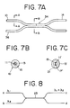
- FIGS. 7A to 7C A construction wherein the connecting portion between the doped fiber 10 and the emergence side optical fiber 14 is formed as a common portion to the optical multiplexer/demultiplexer 34 of the fusion joined fiber type will be described subsequently with reference to FIGS. 7A to 7C.
- end faces of the doped fiber 10 and the emergence side optical fiber 14 are abutted and connected to each other by fusion joining.
- the optical fiber 36 connected to the pumping laser diode 38 is disposed in a juxtaposed relationship with the fiber obtained by such fusion joining, and then, they are heated and drawn or elongated to connect them by fusion joining.
- FIG. 7A includes the core 11 and the clad 13 as shown in FIG. 7B. Meanwhile, a portion of the fibers connected to each other by fusion joining by heating and drawing has such a construction that cores 11′ and 17′ of the doped fiber 10 and optical fiber 36 which have been made thinner by heating and drawing are disposed proximate to each other and the clads of the doped fiber 10 and optical fiber 36 are fused to form a common clad 13′ having an elliptical shape as seen in FIG. 7C.
- the signal light While the signal light is confined in and transmitted along the core 11, it may partly leak to the clad 13 side as indicated by a broken line in FIG. 7B. Meanwhile, where the sectional area of the core 11 is reduced as indicated at 11′ in FIG. 76 while the sectional area of the core of the optical fiber 36 is reduced as indicated at 17′ in FIG. 7C, the amount of the signal light which leaks to the clad 13′ side is increased as indicated by broken lines 19 and 21 in FIG. 7C. As a result, the signal light and the pumping light are combined with each other. Further, where the length of the connected portion by fusion joining by heating and drawing is selected suitably, the combination efficiency or multiplexing efficiency can be increased.
- the sectional area of the abutted fused portion between the doped fiber 10 and the emergence side optical fiber 14 is reduced by the drawing, and if it is reduced, for example, to one half comparing with a sectional area of any other portion, then the amount of reflected light at the abutted fused portion is reduced to one half comparing with that in an alternative case wherein the sectional area is not reduced.
- reflection at the abutted fused portion at which reflection is small comparing with a connector is further reduced by heating and drawing.
- the optical multiplexer/demultiplexer of the fusion joined fiber type shown in FIG. 7A has such a construction wherein it has four ports a, b, c and d as shown in FIG. 8. If light of a wavelength ⁇ 1 is introduced into the optical multiplexer/demultiplexer by way of the port "a" and light of another wavelength ⁇ 2 is introduced in by way of the port b, then they are combined with each other in the fusion joined portion 23 having a length selected in accordance with those wavelengths, and light of the wavelength ⁇ 1 + wavelength ⁇ 2 is forwarded from the port c.
- FIGS, 9A to 9D A process of production of the optical multiplexer/demultiplexer of the fusion joined fiber type shown in FIG. 7A will be described subsequently with reference to FIGS, 9A to 9D.
- a doped fiber and an emergence side optical fiber 14 are abutted with each other between a pair of electrodes 25 and 27 as shown in FIG. 9A, and a voltage is applied between the electrodes 25 and 27 to cause a discharge between them to fuse the abutted portions of the fibers 10 and 14.
- positioning of the doped fiber 10 and optical fiber 14 can be performed under the observation by means of a microscope or in accordance with contents of an indication by an enlarging indicating device which may be a display unit.
- the doped fiber 10 and the optical fiber 14 in most cases have different melting points, it is required to space the discharge position between the electrodes 25 and 27 and the abutting position of the fibers 10 and 14 by a distance of several ⁇ m to several hundreds ⁇ m from each other in accordance with a difference between the melting points.
- an optical fiber 36 is placed in a juxtaposed relationship along the thus fusion joined doped fiber 10 and the optical fiber 14 as shown in FIG. 9B, and then, they are heated by means of an oxyhydrogen burner 29 while the doped fiber 10 and optical fibers 14 and 36 are drawn in the opposite directions as indicated by arrow marks to reduce the outer diameters of them to a value from several ⁇ m to several tens ⁇ m or so and as shown in FIG. 9C fusion join the optical fiber 36 to the doped fiber 10 and the emergence side optical fiber 14 which are fusion joined to each other.
- a reinforcing case made of a metal, plastics or ceramics material or the like is fitted on the thus fusion joined portion of the fibers 10, 14 and 36 and a synthetic resin material for the filling is poured into and solidified in the reinforcing case to form a reinforcing portion 31 as shown in FIG. 9D.
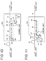
- FIG. 10 shows general construction of another optical fiber amplifier according to a second preferred embodiment of the present invention.
- the optical fiber amplifier is generally denoted at 30b and includes the incidence side optical fiber 12 and the doped fiber 10 connected to each other at a connecting portion 44 provided by fusion joining or the like.
- An optical multiplexer/demultiplexer 46 of the fusion joined fiber type similar to the optical multiplexer/demultiplexer 34 described hereinabove is provided on the incidence side optical fiber 12, and a reflecting film 50 is provided at an end face of an optical fiber 48 of the optical multiplexer/demultiplexer 46.
- the reflecting film 50 may be a reflecting film which only reflects light of a wavelength of pumping light or else a totally reflecting film which reflects light of all wavelengths.
- the other construction of the optical fiber amplifier of the present embodiment is similar to that of the optical fiber amplifier of the first embodiment shown in FIG. 4.
- pumping light emitted from the pumping laser diode 38 and introduced into the doped fiber 10 by way of the optical multiplexer/demultiplexer 34 is separated from signal light by the optical multiplexer/demultiplexer 46 provided adjacent the emergent end of the incidence side optical fiber 12 and is introduced into the optical fiber 48 of the optical multlplexer/demultiplexer 46. Since the reflecting film 50 is provided at the end of the optical fiber 48, the pumping light is reflected by the reflecting film 50 and consequently is introduced back into the doped fiber 10 again by way of the optical multiplexer/demultiplexer 46.
- the signal light is introduced into the optical fiber amplifier 30b by way of the incidence side optical fiber 12 and then passes through the optical multiplexer/demultiplexer 46, whereafter it is introduced into the doped fiber 10 in which it is amplified due to stimulated emission of radiation. After then, it is introduced into the emergence side optical fiber 14 and transmitted along the transmission line.
- optical multiplexer/demultiplexers 34 and 46 in FIGS. 4 and 10 are disposed on the emergence side optical fiber 14 and the incidence side optical fiber 12, they may otherwise be disposed on the opposite ends of the doped optical fiber 10.
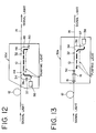
- optical fiber amplifiers of the embodiments shown in FIGS. 4 and 10 employ backward pumping wherein the incidence direction of pumping light is different from the incidence direction of signal light, similar effects can be achieved with an optical fiber amplifier which employs forward pumping wherein pumping light and signal light are introduced in the same direction into the optical fiber amplifier. Exemplary ones of such optical fiber amplifiers are shown in FIGS. 11 and 12.
- the incidence side optical fiber 12 and the doped fiber 10 may otherwise be connected to each other by way of a pair of lenses 16 as shown in FIG. 13.
- the emergence side optical fiber 14 and the doped fiber 10 can be connected to each other in a similar manner.
- a reflecting film 52 is formed on an end face of the doped fiber 10 by vapor deposition or the like.
- FIG. 14 there is shown general construction of a further optical fiber amplifier according to a sixth preferred embodiment of the present invention.
- a pair of optical multiplexer/demultiplexers 34 and 46 of the fusion joined fiber type are connected to each other by way of a connecting optical fiber 62 to form a fiber loop.
- Pumping light emitted from the pumping laser diode 38 is coupled to the fiber loop by way of an optical coupler. 64.
- pumping light emitted from the pumping laser diode 38 passes through the optical coupler 64 and the optical multiplexer/demultiplexer 34 of the fusion joined fiber type and is introduced into the doped fiber 10.
- signal light is introduced into the optical fiber amplifier 60a by way of the incidence side optical fiber 12 and passes through the optical multiplexer/demultiplexer 46, whereafter it is introduced into the doped fiber 10.
- Erbium atoms which have been excited to a high energy level by the pumping light are changed into a ground state by the reception of the signal light, whereupon light is stimulated to emit from the erbium atoms. Consequently, the optical power of the signal light is increased gradually along the optical fiber 10 (that is, the signal light is amplified), and the thus amplified signal light is introduced into the emergence side optical fiber 14.
- the pumping light having passed through the doped fiber 10 is separated from the signal light by the optical multiplexer/demultiplexer 46 and is then transmitted in the connecting optical fiber 62. Then, the pumping light is coupled to the pumping light from the pumping laser diode 38 by the optical coupler 64 and is introduced into the doped fiber 10 by way of the optical multiplexer/demultiplexer 34. Since the pumping light which has been used once is introduced again into the doped fiber 10 by way of the fiber loop in this manner, the amplification efficiency of the optical fiber amplifier is improved.
- the optical fiber amplifier denoted at 60b includes an optical multiplexer/demultiplexer 66 of the fusion joined fiber type provided on the emergence side optical fiber 14 such that pumping light from the pumping laser diode 38 may be directly introduced into the emergence side optical fiber 14 by way of the optical multiplexer/demultiplexer 66.
- a fiber loop for pumping light is formed from the connecting optical fiber 62 in a similar manner as in the optical fiber amplifier of the sixth embodiment shown in FIG. 14.
- rearward scattered light which is produced when pumping light from the pumping laser diode 38 is introduced into the doped fiber 10 can be removed by means of the optical multiplexer/demultiplexer 34 provided on the emergence side optical fiber 14, and such rearward scattered light can be transported in the opposite direction by way of the fiber loop constituted from the connecting optical fiber 62 so that it may be introduced into the doped fiber 10 again.
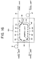
- the optical fiber amplifier generally denoted at 60c includes an additional signal light transmission line for transmitting signal light in the opposite direction to that of the signal light transmission line which is constituted from the incidence side optical fiber 12, the doped fiber 10 and the emergence side optical fiber 14.
- additional signal light transmission line Various components of the additional signal light transmission line are denoted by like reference characters by priming thereof.
- the optical multiplexer/demultiplexer 46 and another optical multiplexer/demultiplexer 34′ are connected to each other by way of a first connecting optical fiber 68 while the optical multiplexer/demultiplexer 34 and another optical multiplexer/demultiplexer 46′ are connected to each other by way of a second connecting optical fiber 70 to form a fiber loop.
- Pumping light emitted from the pumping laser diode 38 is introduced into the second connecting optical fiber 70 by way of the optical coupler 64.
- the optical fiber amplifier of the present embodiment two optically amplifying stations individually constituted from the doped fibers 10 and 10′ are provided in the fiber loop. Since pumping light is gradually attenuated while it is transmitted along the fiber loop, the length of the doped fiber 10′ is preferably made greater than the length of the doped fiber 10 in order to make the two amplifying stations have substantially same amplification factors.
- the optical fiber amplifier of the present embodiment is advantageous in that optical amplification can be effected at a plurality of stations with the single pumping laser diode 38 by using the fiber loop.
- the optical fiber amplifier of the present embodiment includes a plurality of (five in the embodiment shown) signal light transmission lines each including the incidence side optical fiber 12, the doped fiber 10 and the emergence side optical fiber 14.
- the optical fibers which constitute the individual signal light transmission lines are identified with suffixes "a" to "e” applied to individual reference numerals.
- Each adjacent ones of the signal light transmission lines are connected to each other by way of a connecting fiber 72, and an optical multiplexer/demultiplexer 74 is provided at each of such connecting portions.
- the optical fiber amplifier wherein a plurality of optically amplifying stations are provided in the fiber loop is thus constituted with such construction as described just above.
- the doped fibers 10a to 10e are preferably constituted such that the lengths thereof may be increased stepwise in order to make the individual amplifying stations have substantially same amplification factors.
- optical multiplexer/demultiplexer of the fusion joined fiber type is employed in the optical fiber amplifier of any of the embodiments described above, the present invention is not limited to this.
- an optical multiplexer/demultiplexer which employs a dielectric multilayer film, a wavelength separating coupler or the like may be employed instead.
- introduction of signal light into the doped fiber need not be effected by way of the incidence side optical fiber, but signal light may be introduced into the doped fiber directly from a light source such as a laser diode module.
- optical fiber amplifiers of the embodiments shown in FIGS. 14 to 16 all adopt backward pumping wherein the incidence directions of pumping light and signal light are different from each other, similar effects can naturally be achieved even with optical fiber amplifiers which adopt forward pumping wherein the incidence direction of pumping light is reversed so that it may coincide with the incidence direction of signal light.
Landscapes
- Physics & Mathematics (AREA)
- Engineering & Computer Science (AREA)
- Plasma & Fusion (AREA)
- Optics & Photonics (AREA)
- General Physics & Mathematics (AREA)
- Electromagnetism (AREA)
- Lasers (AREA)
- Optical Communication System (AREA)
Claims (11)
- Faseroptischer Verstärker (30a) ausgelegt zur direkten Verstärkung von Signallicht, umfassend:
eine Signallicht-Übertragungsleitung umfassend eine Edelerdenelement-dotierte Faser (10), die mit einem Edelerdenelement dotiert ist;
eine Lichtquelle (38) zum Aussenden von Pumplicht; und
einen ersten optischen Multiplexer/Demultiplexer (34), der in der Signallicht-Übertragungsleitung eingebaut ist, und dessen eines Ende mit der Lichtquelle verbunden ist; und
gekennzeichnet durch:
eine Pumplicht-Reflexionseinrichtung (40, 46, 50) zum Zurückführen von Pumplicht, das mittels des ersten optischen Multiplexers/Demultiplexers in die dotierte Faser eingeleitet worden ist und durch die dotierte Faser gelaufen ist, wieder in die dotierte Faser, wobei die Pumplicht-Reflexionseinrichtung Signallicht transmittiert, aber Pumplicht reflektiert. - Faseroptischer Verstärker nach Anspruch 1,
dadurch gekennzeichnet, daß die Pumplicht-Reflexionseinrichtung ein reflektierender Film ist, der in die Signallicht-Übertragungsleitung eingebaut ist. - Faseroptischer Verstärker nach Anspruch 1,
ferner umfassend einen zweiten optischen Multiplexer/Demultiplexer (46), der in die Signallicht-Übertragungsleitung auf der entgegengesetzten Seite des ersten optischen Multiplexers/Demultiplexers in bezug auf dotierte Faser eingebaut ist, zum Trennen von Signallicht und Pumplicht voneinander, wobei die Pumplicht-Reflexionseinrichtung auf der Pumplicht-Ausgangsseite des zweiten optischen Multiplexers/Demultiplexers vorgesehen ist. - Faseroptischer Verstärker nach Anspruch 3,
dadurch gekennzeichnet, daß die Pumplicht-Reflexionseinrichtung ein reflektierender Film ist, der wenigstens Pumplicht reflektiert. - Faseroptischer Verstärker nach Anspruch 1,
dadurch gekennzeichnet, daß der erste optische Multiplexer/Demultiplexer ein Multiplexer/Demultiplexer des faserversohmolzenen Typs ist, bei dem die dotierte Faser, eine Ausgangsfaser und eine mit der Lichtquelle verbundene Faser verschmolzen und untereinander verbunden sind. - Faseroptischer Verstärker (60a) ausgelegt zur direkten Verstärkung von Signallicht, umfassend:
eine Signallicht-Übertragungsleitung mit einer Edelerdenelement-dotierten Faser (13), die mit einem Edelerdenelement dotiert ist;
eine Lichtquelle (33) zum Aussenden von Pumplicht; und
einen ersten optischen Multiplexer/Demultiplexer (34), der in die Signallicht-Übertragungsleitung eingebaut ist;
gekennzeichnet durch:
einen zweiten optischen Multiplexer/Demultiplexer (46), der in die Signallicht-Übertragungsleitung eingebaut ist, um mit dem ersten optischen Multiplexer/Demultiplexer zusammenzuarbeiten, um die dotierte Faser dazwischen in Sandwich-Bauweise zu enthalten;
eine verbindende Faser (62) zum Verbinden der ersten und zweiten optischen Multiplexer/Demultiplexer miteinander, um eine Faserschleife zu bilden, die die dotierte Faser umfaßt; und
eine Einrichtung (64) zum Verbinden der Lichtquelle mit der Faserschleife. - Faseroptischer Verstärker nach Anspruch 6,
dadurch gekennzeichnet, daß jeder der ersten und zweiten optischen Multiplexer/Demultiplexer ein optischer Multiplexer/Demultiplexer des faserverschmolzenen Typs ist. - Faseroptischer Verstärker (60c) ausgelegt zur direkten Verstärkung von Signallicht, umfassend:
eine erste Signallicht-Übertragungsleitung (10) mit einer Edelerdenelement-dotierten Faser, die mit einem Edelerdenelement dotiert ist;
eine zweite Signallicht-Übertragungsleitung (10′) mit einer zweiten Edelerdenelement-dotierten Faser, die mit einem Edelerdenelement dotiert ist;
eine Lichtquelle (38) zum Aussenden von Pumplicht; und
einen ersten optischen Multiplexer/Demultiplexer (34), der in die erste Signallicht-Übertragungsleitung eingebaut ist;
einen zweiten optischen Multiplexer/Demultiplexer (46), der in die erste Signallicht-Übertragungsleitung zum Zusammenwirken mit dem ersten optischen Multiplexer/Demultiplexer eingebaut ist, um die erste dotierte Faser dazwischen in Sandwich-Bauweise zu beinhalten;
einen dritten optischen Multiplexer/Demultiplexer (34′), der in der zweiten Signallicht-Übertragungsleitung eingebaut ist;
einen vierten optischen Multiplexer/Demultiplexer (46′), der in der zweiten Signallicht-Übertragungsleitung zum Zusammenwirken mit dem dritten optischen Multiplexer/Demultiplexer eingebaut ist, um die zweite dotierte Faser dazwischen in Sandwich-Bauweise zu beinhalten;
eine erste verbindende Faser (68) zum Verbinden der zweiten und dritten optischen Multiplexer/Demultiplexer untereinander; und
eine zweite verbindende Faser (70) zum Verbinden der ersten und vierten optischen Multiplexer/Demultiplexer untereinander, um eine Faserschleife zu bilden, die die ersten und zweiten dotierten Fasern umfaßt; und
eine Einrichtung (64) zum Verbinden der Lichtquelle mit der Faserschleife. - Faseroptischer Verstärker nach Anspruch 8,
dadurch gekennzeichnet, daß jeder der ersten bis vierten optischen Multiplexer/Demultiplexer ein optischer Multiplexer/Demultiplexer des faserverschmolzenen Typs ist. - Faseroptischer Verstärker ausgelegt zum direkten Verstärken von Signallicht, umfassend:
eine Vielzahl von Signalübertragungsleitungen (10a bis 10e), die jeweils eine Edelerdenelement-dotierte Faser umfassen, die mit einem Edelerdenelement dotiert ist;
eine Vielzahl von verbindenden Fasern (72) zum einzelnen Verbinden von benachbarten der Signallicht-Übertragungsleitungen untereinander, um eine Faserschleife zu bilden, die die dotierten Fasern einschließt;
eine Vielzahl von optischen Multiplexern/Demultiplexern (74), die einzeln an Verbindungspunkten zwischen den Signallicht-Übertragungsleitungen und den verbindenden Fasern vorgesehen sind, um Signallicht dadurch zu führen, aber eine Zirkulation von Pumplicht in der Faserschleife zu bewirken;
eine Lichtquelle (38) zum Aussenden von Pumplicht; und
eine Einrichtung (64) zum Verbinden der Lichtquelle mit der Faserschleife. - Faseroptischer Verstärker nach Anspruch 10,
dadurch gekennzeichnet, daß jeder der Vielzahl von optischen Multiplexern/Demultiplexern ein optischer Multiplexer/Demultiplexer des faserverschmolzenen Typs ist.
Applications Claiming Priority (4)
| Application Number | Priority Date | Filing Date | Title |
|---|---|---|---|
| JP159736/89 | 1989-06-23 | ||
| JP1159736A JPH0325985A (ja) | 1989-06-23 | 1989-06-23 | 光ファイバ増幅器 |
| JP182629/89 | 1989-07-17 | ||
| JP1182629A JPH0348472A (ja) | 1989-07-17 | 1989-07-17 | 光ファイバ増幅器 |
Publications (3)
| Publication Number | Publication Date |
|---|---|
| EP0404152A2 EP0404152A2 (de) | 1990-12-27 |
| EP0404152A3 EP0404152A3 (de) | 1991-10-23 |
| EP0404152B1 true EP0404152B1 (de) | 1995-09-06 |
Family
ID=26486447
Family Applications (1)
| Application Number | Title | Priority Date | Filing Date |
|---|---|---|---|
| EP90111762A Expired - Lifetime EP0404152B1 (de) | 1989-06-23 | 1990-06-21 | Lichtverstärker mit optischer Faser |
Country Status (4)
| Country | Link |
|---|---|
| US (1) | US5136420A (de) |
| EP (1) | EP0404152B1 (de) |
| CA (1) | CA2019253C (de) |
| DE (1) | DE69022129T2 (de) |
Families Citing this family (49)
| Publication number | Priority date | Publication date | Assignee | Title |
|---|---|---|---|---|
| US5179603A (en) * | 1991-03-18 | 1993-01-12 | Corning Incorporated | Optical fiber amplifier and coupler |
| FR2675592B1 (fr) * | 1991-04-22 | 1993-07-16 | Alcatel Nv | Amplificateur optique dans le domaine spectral 1,26 a 1,34 mum. |
| DK168180B1 (da) * | 1991-07-19 | 1994-02-21 | Lycom As | Fremgangsmåde til at forstærke et optisk signal, optisk forstærker til udøvelse af fremgangsmåden, og anvendelse af en sådan optisk forstærker som lyskilde |
| US5173957A (en) * | 1991-09-12 | 1992-12-22 | At&T Bell Laboratories | Pump redundancy for optical amplifiers |
| DE69224340T2 (de) * | 1991-09-30 | 1998-06-04 | Nippon Electric Co | Zweiwegzwischenverstärker mit optischer Verstärkung |
| DE69228393T2 (de) * | 1991-11-08 | 1999-06-17 | Mitsubishi Denki K.K., Tokio/Tokyo | Faseroptischer Verstärker |
| WO1993018561A1 (en) * | 1992-03-13 | 1993-09-16 | Raychem Corporation | Ring laser pumped optical amplifier |
| US5253104A (en) * | 1992-09-15 | 1993-10-12 | At&T Bell Laboratories | Balanced optical amplifier |
| JP3247919B2 (ja) * | 1993-07-19 | 2002-01-21 | 三菱電機株式会社 | 光増幅装置 |
| US5408356A (en) * | 1993-08-02 | 1995-04-18 | The United States Of America As Represented By The United States Department Of Energy | Fiber optic signal amplifier using thermoelectric power generation |
| US5448586A (en) * | 1993-09-20 | 1995-09-05 | At&T Corp. | Pumping arrangements for arrays of planar optical devices |
| US5430572A (en) * | 1993-09-30 | 1995-07-04 | At&T Corp. | High power, high gain, low noise, two-stage optical amplifier |
| JP3012760B2 (ja) * | 1993-10-25 | 2000-02-28 | 三菱電機株式会社 | 光増幅器及び分配システム及びローカル・エリア・ネットワーク及び利得制御方法 |
| US5394265A (en) * | 1993-10-25 | 1995-02-28 | At&T Corp. | In-line two-stage erbium doped fiber amplifier system with in-band telemetry channel |
| US5396506A (en) * | 1993-12-09 | 1995-03-07 | United Technologies Corporation | Coupled multiple output fiber laser |
| JP3423761B2 (ja) * | 1994-03-02 | 2003-07-07 | 東北パイオニア株式会社 | 光波長変換装置 |
| FR2721158B1 (fr) * | 1994-06-14 | 1996-07-12 | Alcatel Submarcom | Système de transmission sur une ligne à fibre optique sans répéteur, avec amplifications distante et locale. |
| EP0729207A3 (de) * | 1995-02-24 | 1997-10-15 | At & T Corp | Faseroptischer Verstärker mit optischem Zirkulator |
| EP2503655A3 (de) | 1995-03-20 | 2013-02-27 | Fujitsu Limited | Faseroptischer Verstärker und dispersionskompensierendes Fasermodul für faseroptischen Verstärker |
| JPH10157199A (ja) * | 1996-11-27 | 1998-06-16 | Dainippon Screen Mfg Co Ltd | 画像記録装置 |
| US6477295B1 (en) | 1997-01-16 | 2002-11-05 | Jds Uniphase Corporation | Pump coupling of double clad fibers |
| US5768012A (en) * | 1997-03-07 | 1998-06-16 | Sdl, Inc. | Apparatus and method for the high-power pumping of fiber optic amplifiers |
| JP3597999B2 (ja) * | 1997-12-26 | 2004-12-08 | 京セラ株式会社 | 光ファイバカップラとその製造方法及びそれを用いた光増幅器 |
| JPH11275021A (ja) * | 1998-03-20 | 1999-10-08 | Fujitsu Ltd | 光増幅装置 |
| JP4179662B2 (ja) | 1998-04-27 | 2008-11-12 | 富士通株式会社 | 光増幅器及び能動型光ファイバ |
| JPH11307844A (ja) * | 1998-04-27 | 1999-11-05 | Fujitsu Ltd | 能動型光ファイバ及び光ファイバ増幅器 |
| US6122413A (en) * | 1998-10-20 | 2000-09-19 | Optigain, Inc. | Fiber optic transmitter |
| JP4237871B2 (ja) * | 1999-05-27 | 2009-03-11 | 京セラ株式会社 | 光ファイバカップラとその製造方法及びこれを用いた光増幅器 |
| KR100326119B1 (ko) | 1999-06-23 | 2002-03-07 | 윤종용 | 씨드-빔을 이용한 엘-밴드 광섬유 증폭기 |
| KR100334809B1 (ko) | 1999-07-21 | 2002-05-02 | 윤종용 | 씨드-빔을 이용한 광대역 광원 |
| US6538817B1 (en) | 1999-10-25 | 2003-03-25 | Aculight Corporation | Method and apparatus for optical coherence tomography with a multispectral laser source |
| US6501782B1 (en) | 1999-10-25 | 2002-12-31 | Aculight Corporation | Compact laser apparatus |
| US6456756B1 (en) | 1999-10-25 | 2002-09-24 | Aculight Corporation | Fiber raman amplifier pumped by an incoherently beam combined diode laser |
| US6529542B1 (en) | 2000-04-04 | 2003-03-04 | Aculight Corporation | Incoherent beam combined optical system utilizing a lens array |
| WO2002103419A2 (en) * | 2000-11-27 | 2002-12-27 | Photon-X, Inc. | Compact optical fiber amplifier module |
| US6724528B2 (en) | 2001-02-27 | 2004-04-20 | The United States Of America As Represented By The Secretary Of The Navy | Polarization-maintaining optical fiber amplifier employing externally applied stress-induced birefringence |
| EP1255139A1 (de) * | 2001-05-03 | 2002-11-06 | Corning Incorporated | Verfahren und Apparat zum Spleissen von Glasfasern |
| WO2003044569A2 (en) * | 2001-11-19 | 2003-05-30 | Photon-X, Inc. | L band optical amplifier |
| US6690507B2 (en) | 2002-01-30 | 2004-02-10 | Corning Incorporated | Double-pumped raman amplifier |
| US7113328B2 (en) * | 2002-03-11 | 2006-09-26 | Telefonaktiebolaget Lm Ericsson (Publ) | Dual-wavelength pumped thulium-doped optical fiber amplifier |
| JP2003298527A (ja) * | 2002-04-02 | 2003-10-17 | Fujitsu Ltd | ラマン増幅を用いた光ファイバ伝送のための方法及び装置 |
| US7046432B2 (en) * | 2003-02-11 | 2006-05-16 | Coherent, Inc. | Optical fiber coupling arrangement |
| US7876497B2 (en) * | 2008-05-09 | 2011-01-25 | Institut National D'optique | Multi-stage long-band optical amplifier with ASE re-use |
| JP5512348B2 (ja) * | 2010-03-29 | 2014-06-04 | 株式会社フジクラ | 光学部品付き増幅用光ファイバ、及び、これを用いたファイバレーザ装置 |
| US8578739B2 (en) * | 2010-10-04 | 2013-11-12 | National Applied Research Laboratories | Shorter wavelength photo-annealing apparatus for rare-earth-doped fiber and its optical assemblies under irradiation |
| US8903211B2 (en) * | 2011-03-16 | 2014-12-02 | Ofs Fitel, Llc | Pump-combining systems and techniques for multicore fiber transmissions |
| JP6998754B2 (ja) * | 2017-12-15 | 2022-01-18 | 古河電気工業株式会社 | 光結合器及び光増幅器 |
| US11621778B2 (en) | 2019-06-11 | 2023-04-04 | Nippon Telegraph And Telephone Corporation | Optical communication system and optical communication method |
| WO2021240731A1 (ja) | 2020-05-28 | 2021-12-02 | 日本電信電話株式会社 | 光漏洩確認方法、光漏洩確認装置、およびプログラム |
Family Cites Families (12)
| Publication number | Priority date | Publication date | Assignee | Title |
|---|---|---|---|---|
| US4132955A (en) * | 1974-08-01 | 1979-01-02 | Helen Hughes | System for amplifying laser beams |
| US4225826A (en) * | 1978-02-03 | 1980-09-30 | The University Of Rochester | Laser apparatus |
| US5048026A (en) * | 1983-09-30 | 1991-09-10 | The Board Of Trustees Of The Leland Stanford Junior University | Fiber optic amplifier |
| US4938556A (en) * | 1983-11-25 | 1990-07-03 | The Board Of Trustees Of The Leland Stanford Junior University | Superfluorescent broadband fiber laser source |
| US4637025A (en) * | 1984-10-22 | 1987-01-13 | Polaroid Corporation | Super radiant light source |
| FR2573547B1 (fr) * | 1984-11-16 | 1987-04-10 | Thomson Csf | Source optique monomode et dispositif amplificateur optique accordables dans le proche infra-rouge et l'application aux dispositifs amplificateurs selectifs et de regeneration |
| US4794598A (en) * | 1986-07-18 | 1988-12-27 | The Board Of Trustees Of The Leland Stanford Junior University | Synchronously pumped ring fiber Raman laser |
| GB8512980D0 (en) * | 1985-05-22 | 1985-06-26 | Pa Consulting Services | Fibre optic transmissions systems |
| US4778238A (en) * | 1985-08-01 | 1988-10-18 | Hicks John W | Optical communications systems and process for signal amplification using stimulated brillouin scattering (SBS) and laser utilized in the system |
| US4712075A (en) * | 1985-11-27 | 1987-12-08 | Polaroid Corporation | Optical amplifier |
| US4782491A (en) * | 1987-04-09 | 1988-11-01 | Polaroid Corporation | Ion doped, fused silica glass fiber laser |
| IT1237135B (it) * | 1989-10-30 | 1993-05-24 | Pirelli Cavi Spa | Gruppo di amplificazione ottico a basso rumore, con riflessione della potenza di pompaggio. |
-
1990
- 1990-06-19 CA CA002019253A patent/CA2019253C/en not_active Expired - Fee Related
- 1990-06-21 DE DE69022129T patent/DE69022129T2/de not_active Expired - Fee Related
- 1990-06-21 EP EP90111762A patent/EP0404152B1/de not_active Expired - Lifetime
- 1990-06-21 US US07/541,822 patent/US5136420A/en not_active Expired - Lifetime
Also Published As
| Publication number | Publication date |
|---|---|
| DE69022129T2 (de) | 1996-03-21 |
| DE69022129D1 (de) | 1995-10-12 |
| CA2019253A1 (en) | 1990-12-23 |
| EP0404152A2 (de) | 1990-12-27 |
| CA2019253C (en) | 1994-01-11 |
| US5136420A (en) | 1992-08-04 |
| EP0404152A3 (de) | 1991-10-23 |
Similar Documents
| Publication | Publication Date | Title |
|---|---|---|
| EP0404152B1 (de) | Lichtverstärker mit optischer Faser | |
| EP0415167B1 (de) | Optische Verstärker | |
| US6462864B1 (en) | Dual substrate laminate-configured optical channel for multi-fiber ribbon form factor-compliant integrated multi-channel optical amplifier | |
| US6434295B1 (en) | Side coupled pumping of double clad fiber gain media | |
| US20060187541A1 (en) | Optical fiber coupling arrangement | |
| EP1639679B1 (de) | Optische vorrichtung | |
| EP0444694B1 (de) | Optischer Koppler | |
| US20080267227A1 (en) | Gain-clamped optical amplifier using double-clad fiber | |
| US6542677B2 (en) | Amplification optical fiber and fiber optic amplifier including the same | |
| JP4237871B2 (ja) | 光ファイバカップラとその製造方法及びこれを用いた光増幅器 | |
| JP3152432B2 (ja) | 光ファイバ通信線用増幅器および同増幅器を含む通信線 | |
| US6020991A (en) | Optical amplifier | |
| JPH0325985A (ja) | 光ファイバ増幅器 | |
| US5473713A (en) | Optical amplifier having a doped fluoride glass optical fibre and process for producing this amplifier | |
| EP0926519B1 (de) | Optischer Faserkoppler, Herstellungsverfahren dafür und optischer Verstärker mit diesem Faserkoppler | |
| JP2955780B2 (ja) | 光ファイバ増幅器 | |
| JPH0888430A (ja) | 光ファイバ増幅器 | |
| EP0939466A2 (de) | Lichtquelle mit WDM-Funktion, optischer Verstärker und bidirektionales Ubertragungssystem unter Verwendung derselben | |
| JP3215236B2 (ja) | 光ファイバ増幅器 | |
| JPH06224497A (ja) | 光増幅器 | |
| JP2003322749A (ja) | 分散補償モジュールおよび光通信システム | |
| JPH05136486A (ja) | 光増幅用icチツプ | |
| JP2000105325A (ja) | 光ファイバーコリメータとこれを用いた光モジュール及び光増幅器 | |
| JP2001127364A (ja) | 光ファイバ増幅器及びそのパッケージ方法 | |
| JPH0348472A (ja) | 光ファイバ増幅器 |
Legal Events
| Date | Code | Title | Description |
|---|---|---|---|
| PUAI | Public reference made under article 153(3) epc to a published international application that has entered the european phase |
Free format text: ORIGINAL CODE: 0009012 |
|
| AK | Designated contracting states |
Kind code of ref document: A2 Designated state(s): DE FR GB |
|
| PUAL | Search report despatched |
Free format text: ORIGINAL CODE: 0009013 |
|
| AK | Designated contracting states |
Kind code of ref document: A3 Designated state(s): DE FR GB |
|
| 17P | Request for examination filed |
Effective date: 19920225 |
|
| 17Q | First examination report despatched |
Effective date: 19931014 |
|
| GRAA | (expected) grant |
Free format text: ORIGINAL CODE: 0009210 |
|
| AK | Designated contracting states |
Kind code of ref document: B1 Designated state(s): DE FR GB |
|
| REF | Corresponds to: |
Ref document number: 69022129 Country of ref document: DE Date of ref document: 19951012 |
|
| ET | Fr: translation filed | ||
| PLBQ | Unpublished change to opponent data |
Free format text: ORIGINAL CODE: EPIDOS OPPO |
|
| PLBI | Opposition filed |
Free format text: ORIGINAL CODE: 0009260 |
|
| PLBF | Reply of patent proprietor to notice(s) of opposition |
Free format text: ORIGINAL CODE: EPIDOS OBSO |
|
| 26 | Opposition filed |
Opponent name: ALCATEL KABEL BETEILIGUNGS-AG Effective date: 19960601 |
|
| PLBF | Reply of patent proprietor to notice(s) of opposition |
Free format text: ORIGINAL CODE: EPIDOS OBSO |
|
| PLBO | Opposition rejected |
Free format text: ORIGINAL CODE: EPIDOS REJO |
|
| APAC | Appeal dossier modified |
Free format text: ORIGINAL CODE: EPIDOS NOAPO |
|
| APAE | Appeal reference modified |
Free format text: ORIGINAL CODE: EPIDOS REFNO |
|
| APAC | Appeal dossier modified |
Free format text: ORIGINAL CODE: EPIDOS NOAPO |
|
| PLBQ | Unpublished change to opponent data |
Free format text: ORIGINAL CODE: EPIDOS OPPO |
|
| PLAB | Opposition data, opponent's data or that of the opponent's representative modified |
Free format text: ORIGINAL CODE: 0009299OPPO |
|
| R26 | Opposition filed (corrected) |
Opponent name: ALCATEL KABEL BETEILIGUNGS-AG Effective date: 19960601 |
|
| APAC | Appeal dossier modified |
Free format text: ORIGINAL CODE: EPIDOS NOAPO |
|
| PLBN | Opposition rejected |
Free format text: ORIGINAL CODE: 0009273 |
|
| STAA | Information on the status of an ep patent application or granted ep patent |
Free format text: STATUS: OPPOSITION REJECTED |
|
| REG | Reference to a national code |
Ref country code: GB Ref legal event code: IF02 |
|
| 27O | Opposition rejected |
Effective date: 20011026 |
|
| PGFP | Annual fee paid to national office [announced via postgrant information from national office to epo] |
Ref country code: FR Payment date: 20050608 Year of fee payment: 16 |
|
| PGFP | Annual fee paid to national office [announced via postgrant information from national office to epo] |
Ref country code: GB Payment date: 20050615 Year of fee payment: 16 |
|
| PGFP | Annual fee paid to national office [announced via postgrant information from national office to epo] |
Ref country code: DE Payment date: 20050616 Year of fee payment: 16 |
|
| APAH | Appeal reference modified |
Free format text: ORIGINAL CODE: EPIDOSCREFNO |
|
| PG25 | Lapsed in a contracting state [announced via postgrant information from national office to epo] |
Ref country code: GB Free format text: LAPSE BECAUSE OF NON-PAYMENT OF DUE FEES Effective date: 20060621 |
|
| PG25 | Lapsed in a contracting state [announced via postgrant information from national office to epo] |
Ref country code: DE Free format text: LAPSE BECAUSE OF NON-PAYMENT OF DUE FEES Effective date: 20070103 |
|
| GBPC | Gb: european patent ceased through non-payment of renewal fee |
Effective date: 20060621 |
|
| REG | Reference to a national code |
Ref country code: FR Ref legal event code: ST Effective date: 20070228 |
|
| PG25 | Lapsed in a contracting state [announced via postgrant information from national office to epo] |
Ref country code: FR Free format text: LAPSE BECAUSE OF NON-PAYMENT OF DUE FEES Effective date: 20060630 |
|
| PLAB | Opposition data, opponent's data or that of the opponent's representative modified |
Free format text: ORIGINAL CODE: 0009299OPPO |