EP0403693A2 - Dispositif pour obtenir un couple pour un système de conversion de mouvement, spécialement pour l'ajustement des mors d'un mandrin ou de la force de serrage - Google Patents
Dispositif pour obtenir un couple pour un système de conversion de mouvement, spécialement pour l'ajustement des mors d'un mandrin ou de la force de serrage Download PDFInfo
- Publication number
- EP0403693A2 EP0403693A2 EP89120452A EP89120452A EP0403693A2 EP 0403693 A2 EP0403693 A2 EP 0403693A2 EP 89120452 A EP89120452 A EP 89120452A EP 89120452 A EP89120452 A EP 89120452A EP 0403693 A2 EP0403693 A2 EP 0403693A2
- Authority
- EP
- European Patent Office
- Prior art keywords
- wheels
- adjusting
- gear
- work spindle
- driven
- Prior art date
- Legal status (The legal status is an assumption and is not a legal conclusion. Google has not performed a legal analysis and makes no representation as to the accuracy of the status listed.)
- Granted
Links
Images
Classifications
-
- B—PERFORMING OPERATIONS; TRANSPORTING
- B23—MACHINE TOOLS; METAL-WORKING NOT OTHERWISE PROVIDED FOR
- B23B—TURNING; BORING
- B23B31/00—Chucks; Expansion mandrels; Adaptations thereof for remote control
- B23B31/02—Chucks
- B23B31/24—Chucks characterised by features relating primarily to remote control of the gripping means
- B23B31/28—Chucks characterised by features relating primarily to remote control of the gripping means using electric or magnetic means in the chuck
-
- B—PERFORMING OPERATIONS; TRANSPORTING
- B23—MACHINE TOOLS; METAL-WORKING NOT OTHERWISE PROVIDED FOR
- B23B—TURNING; BORING
- B23B2260/00—Details of constructional elements
- B23B2260/062—Electric motors
-
- Y—GENERAL TAGGING OF NEW TECHNOLOGICAL DEVELOPMENTS; GENERAL TAGGING OF CROSS-SECTIONAL TECHNOLOGIES SPANNING OVER SEVERAL SECTIONS OF THE IPC; TECHNICAL SUBJECTS COVERED BY FORMER USPC CROSS-REFERENCE ART COLLECTIONS [XRACs] AND DIGESTS
- Y10—TECHNICAL SUBJECTS COVERED BY FORMER USPC
- Y10T—TECHNICAL SUBJECTS COVERED BY FORMER US CLASSIFICATION
- Y10T82/00—Turning
- Y10T82/25—Lathe
- Y10T82/2531—Carriage feed
-
- Y—GENERAL TAGGING OF NEW TECHNOLOGICAL DEVELOPMENTS; GENERAL TAGGING OF CROSS-SECTIONAL TECHNOLOGIES SPANNING OVER SEVERAL SECTIONS OF THE IPC; TECHNICAL SUBJECTS COVERED BY FORMER USPC CROSS-REFERENCE ART COLLECTIONS [XRACs] AND DIGESTS
- Y10—TECHNICAL SUBJECTS COVERED BY FORMER USPC
- Y10T—TECHNICAL SUBJECTS COVERED BY FORMER US CLASSIFICATION
- Y10T82/00—Turning
- Y10T82/25—Lathe
- Y10T82/2552—Headstock
- Y10T82/2558—Spindle reverser
-
- Y—GENERAL TAGGING OF NEW TECHNOLOGICAL DEVELOPMENTS; GENERAL TAGGING OF CROSS-SECTIONAL TECHNOLOGIES SPANNING OVER SEVERAL SECTIONS OF THE IPC; TECHNICAL SUBJECTS COVERED BY FORMER USPC CROSS-REFERENCE ART COLLECTIONS [XRACs] AND DIGESTS
- Y10—TECHNICAL SUBJECTS COVERED BY FORMER USPC
- Y10T—TECHNICAL SUBJECTS COVERED BY FORMER US CLASSIFICATION
- Y10T82/00—Turning
- Y10T82/25—Lathe
- Y10T82/2552—Headstock
- Y10T82/2562—Spindle and bearings
Definitions
- the invention relates to a device for generating an actuating torque for a movement conversion system, in particular for adjusting the jaws of a chuck or the clamping force exerted by them, with a work spindle of a machine tool that can be driven to rotate and an adjusting rod that is adjustably arranged in the hollow work spindle, the movement conversion system at the
- the work spindle is arranged in a revolving manner, two adjusting wheels arranged coaxially to the work spindle and rotatable relative to one another for actuating the movement conversion system in opposite directions of rotation are provided and a planetary differential is arranged in the drive train between these adjusting wheels and a stationary servomotor which branches the rotary movement or the torque of the servomotor onto the two adjusting wheels.
- the differential is designed as a two-stage synchronous gear in the manner of a countershaft transmission, the central wheels of which are coupled in synchronism by two counterswheels arranged in a rotationally fixed manner on the countershaft, the countershaft rotatably mounted around the central wheels being supported on the output element of a torque clutch connected downstream of the servomotor.
- the electric servomotor always rotates at the same speed and direction of rotation, whereby the state of equilibrium between the torque transmitted by the torque clutch and the applied clamping force is established by automatically rotating the countershaft around the main shaft of the countershaft transmission.
- a helical gear is provided as the movement conversion system, with which the initiated rotary movement into a Axial movement is implemented, which is communicated to the actuating rod which is guided axially adjustably in the hollow drive spindle.
- the electric servomotor has a rotor which rotates continuously with the work spindle and which is accelerated or braked by changing the motor current in order to exert the actuating torque.
- the resulting reaction actuating torque on the motion conversion system is supported on the work spindle and its rotary drive on stationary components in order to close the flow of force which adjusts the motion conversion system.
- the invention has for its object to provide a device of the type mentioned in such a way that the movement conversion system enables an axially adjustable actuating rod to be actuated directly without the actuating torque being exerted on the work spindle, and that the actuation required to generate a specific actuating torque of the servomotor is independent of the speed of the work spindle and therefore the actuating torque is uniquely determined without a regulating process solely by a predetermined control of the servomotor.
- the adjusting wheels which can be rotated relative to the working spindle, are in drive connection with tensioning threaded spindles which are mounted on the working spindle so as to be rotatable and axially non-displaceable, are arranged parallel to the axis and eccentrically to the axis of the working spindle and are provided with their clamping thread in the axially adjustable adjusting rod Threaded receptacles run, wherein the threaded screw spindles that are in drive connection with the adjusting wheel have the reverse thread sense as the threaded screw spindles in drive connection with the other adjusting wheel.
- the two adjusting wheels convert the rotating actuating movement directly via the clamping threaded spindles into an axial actuating movement of the actuating rod and work completely symmetrically with respect to the introduction of the actuating torque into the movement conversion system and also the support of the reaction actuating torque, that is, it does not work for another support member requirement.
- the actuating torque acts on one setting wheel, the reaction actuating torque on the other, and vice versa.
- the work spindle remains unaffected by the actuating or reaction actuating torque, since both adjusting wheels are rotatably mounted on the work spindle.
- the adjusting wheels take part in the rotation of the work spindle, however, due to the symmetry ratio, the rotation of the two adjusting wheels in the differential gear is completely canceled against each other, so that the drive member of the differential gear is stationary even when the work spindle is running, as long as the two adjusting wheels are not Operation of the movement conversion system can be adjusted relative to each other and the servomotor is controlled accordingly.
- the servomotor its motor part, which adjusts when the servomotor is activated and actuates the drive element of the differential, is always completely decoupled from the rotation of the work spindle.
- the servomotor therefore does not need to have a rotor, but can have a very simple structure, for example also a cylinder-piston arrangement, which rotates the drive member of the differential gear via the toothed rack and pinion to the extent necessary for the opposite relative adjustment of both adjusting wheels on the stationary or rotating one Work spindle is required to get the actuating torque in the desired size.
- the actuating torque is also completely independent of the speed of the work spindle. Changes in the spindle speed leave the servomotor completely unaffected, so that the actuating torque acting on the setting wheels is determined solely by the actuation and adjustment of the servomotor and not also by the spindle speed. As a result, all control processes for maintaining a certain actuating torque regardless of the speed of the work spindle are unnecessary.
- a particularly expedient embodiment is characterized in that the threaded receptacles for the screw leadscrews are arranged in a flange of the adjusting rod and the adjusting wheels and the leadscrews are mounted on a flange of the work spindle, whereby mesh the adjusting wheels in a toothing with toothed pinions which are non-rotatable on the clamping threaded spindles and which, like the adjusting wheels, are arranged on both sides of the flange of the working spindle. It is best if the adjusting wheels each have an internal ring gear with which the pinions are in engagement.
- the epicyclic differential is designed as a bevel gear differential gear, in which the rotary movement initiated by the servomotor via a drive member is diverted via two driven wheels connected in opposite directions by at least one differential gear, which are connected to one of the adjusting wheels each is in rotary connection, with a reversal of the direction of rotation taking place in the rotating connection between one of the driven wheels and the corresponding adjusting wheel such that this driven wheel and the adjusting wheel rotate in opposite directions to one another.
- two drive wheels connected to the setting wheels and rotating with them in the same direction are provided, one of which is connected directly and the other is connected via a gear reversing direction to each of the driven wheels, so that the intermediate wheel and the driven wheel are connected via the Reversing gears are connected, rotate in opposite directions to each other.
- the adjusting wheels can each be connected to their idler gear by a toothed belt.
- the output gears and the intermediate gears are expediently arranged coaxially and, together with the gear members of the gear reversing the direction of rotation, are mounted on a stationary gear housing which holds the output gears and the drive member surrounds with the balance wheels mounted on the drive member and running between the driven wheels, while the intermediate wheels are arranged axially next to one another on the same side outside the transmission housing.
- the driven wheels are axially opposite one another with stub axles facing away from one another in the wall of the transmission housing, that in the hollow stub axles of both driven wheels a drive shaft actuated by the servo motor and supporting the drive member in a rotationally fixed manner is mounted, wherein the drive member directed radially to the drive shaft, the differential gears bearing journal, and that the idler gear, which is connected to the driven gear via the reversing gear, is rotatably mounted on the stub axle of the other driven gear on which the second idler gear sits in a rotationally fixed manner.
- the driven wheels, the intermediate wheels and the adjusting wheels each have the same drive diameter, so that they each have the same speed or angle of rotation.
- the servomotor can be a rotary field magnet with a stationary stator and with a rotor that is in rotary connection with the drive shaft of the differential gear for simple power transmission to the differential gear, but, to emphasize it again, the rotor does not turn on when transmitting the actuating torque participates in the rotation of the work spindle.
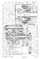
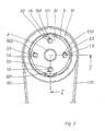
- the section line I-I entered in FIG. 2 corresponds to the axial section shown in FIG. 1.
- the hollow drive spindle 1 of a machine tool which is otherwise not shown, is only partially reproduced, in particular without its bearings in the machine frame and without the drive device which rotates the work spindle.
- a hollow actuating rod 2 is guided axially displaceably in the work spindle 1 and can be adjusted axially in the work spindle 1 with the aid of a movement conversion system, generally designated 3, in order, for example, to adjust the jaws of a chuck, not shown, located at the head of the work spindle 1.
- the entire movement conversion system 3 is arranged on the work spindle 1 and is operated by a stationary servomotor 4.
- a differential or differential gear is arranged between the adjusting wheels 61, 62 and the servomotor 4, in which the rotary movement initiated by the servomotor 4 via a drive member 8 is diverted via two driven wheels 91, 92, the adjusting wheels 61, 62, the driven wheels 91, 92 and the drive member 8 are arranged axially parallel.
- the driven wheels 91, 92 are each in rotary connection with one of the adjusting wheels 61, 62, wherein in the rotating connection between the driven wheel 91 and the corresponding adjusting wheel 61 the direction of rotation is reversed such that this driven wheel 91 and the adjusting wheel 61 rotate in opposite directions to one another.
- the two adjusting wheels 61, 62 are connected via an external toothing and toothed belt 101, 102 with toothed intermediate wheels 201, 202, which are also toothed on the outer circumference and are parallel to the axis with the adjusting wheels 61, 62 and in the same direction.
- One idler gear 202 is connected directly to the driven gear 92, the other idler gear 201 is connected to the other driven gear 9 via a gear 30 reversing the direction of rotation such that this idler gear 201 and the driven gear 91 rotate in opposite directions to one another.
- the driven gears 91, 92 and the intermediate gears 201, 202 are arranged coaxially and, together with the gear members 301 to 306 of the reversing gear 30, are mounted on a stationary gear housing 11, which holds the driven gears 91, 92 and the drive member 8 of the differential 7 surrounded on the drive member 8, running between the driven wheels 91, 92 balance wheels 12.
- the intermediate wheels 201, 202 are arranged on the same side outside the gear housing 11.
- the driven wheels 91, 92 lie axially opposite one another and are mounted in the wall of the transmission housing 11 with stub axles 401, 402 facing away from one another.
- a drive shaft 13 which is actuated by the servomotor 4 and supports the drive member 8 in a rotationally fixed manner, is mounted.
- the drive member 8 has radially directed to the drive shaft 13, the differential gears 12 bearing journals 14, only two of these journals 14 and differential gears 12 can be seen in FIG. 1.
- the intermediate gear 201 which is connected to its driven gear 91 via the gear 30 reversing the direction of rotation, is rotatably seated on the stub axle 402 of the other driven gear 92, the second idler gear 202 being seated on this stub axle 402 in a rotationally fixed manner.
- the gear 30 reversing the direction of rotation transmits the rotational movement of the driven wheel 91 to the axially opposite side of the gear housing 11, so that the two intermediate wheels 201, 202 and accordingly the adjusting wheels 61, 62 can be arranged axially close to one another.
- the gear 30 reversing the direction of rotation comprises a gear wheel 301 on the stub axle 401 of the driven gear 91, the movement of which is transmitted via an inserted gear wheel 302 to a gear shaft 303 mounted parallel to the drive shaft 13 of the differential gear 7 in the gear housing 11.
- This gear shaft 303 extends from one to the other end wall of the gear housing 11, where its rotational movement is transmitted via two meshing gears 304, 305 to a sleeve 15 carrying the idler gear 201, which engages with the gear 305 with external teeth 306 and is rotatably mounted on the stub axle 402 of the driven gear 92 and idler gear 202.
- the driven wheels 91, 92, the intermediate wheels 201, 202 and the adjusting wheels 61, 62 each have the same drive diameter.
- the servomotor 4 is a rotating field magnet with a stationary stator 4.1 and a rotor which is in rotary connection with the drive shaft 13 of the differential 7 via a toothed belt and has an output shaft operated by the rotor.
- Clamping thread spindles 501, 502, which are arranged parallel to the axis and eccentrically to the axis of the work spindle 1, are rotatably and axially immovably mounted on the flange 5 of the work spindle 1.
- the clamping thread spindles 501, 502 each have a clamping thread pin 19 with a clamping thread 20.
- the clamping thread pin 19 runs in threaded receptacles which are provided in a flange 21 of the actuating rod 2. All tensioning thread spindles 501, which are in engagement with the same adjusting wheel 61, have the same thread direction of their tensioning thread 20, but the opposite thread direction as the tensioning thread spindles 502 which are in drive connection with the other adjusting wheel 62.
- the two adjusting wheels 61, 62 are rotated in opposite directions relative to one another, the actuating torques acting on the adjusting wheels being opposite in the direction of rotation, but are otherwise of the same size.
- the work spindle 1 remains unaffected by these actuating torques.
- the tensioning threaded spindles 501 which are driven by one adjusting wheel 61, move correspondingly in the opposite direction of rotation as the threaded spindles 502 driven by the other adjusting wheel 62.
- the threaded direction of the tensioning thread 20 on the tensioning threaded spindles 501 and 502 is opposite, the rotation of all the tensioning threaded spindles nevertheless results different direction of rotation the same axial adjustment of the Control rod 2.
- the entire movement conversion system 3 rotates with it, in particular therefore the two adjusting wheels 61, 62 also rotate with the work spindle 1, both in the same direction.
- This rotational movement in the same direction is transmitted to the intermediate wheels 201, 202, which thus also rotate in the same direction.
- the driven wheels 91, 92 of the differential 7 connected to the intermediate wheels rotate in opposite directions of rotation because of the gear 30, so that the differential gears 12 rotate about their journals 14, but the drive member 8 of the differential 7 remains stationary with the drive shaft 13, so that the rotor of the servomotor 4 does not experience any rotation.
Landscapes
- Engineering & Computer Science (AREA)
- Mechanical Engineering (AREA)
- Gripping On Spindles (AREA)
- Details Of Spanners, Wrenches, And Screw Drivers And Accessories (AREA)
- Retarders (AREA)
- Constituent Portions Of Griding Lathes, Driving, Sensing And Control (AREA)
Priority Applications (3)
| Application Number | Priority Date | Filing Date | Title |
|---|---|---|---|
| AT89120452T ATE85251T1 (de) | 1989-06-23 | 1989-11-04 | Vorrichtung zum erzeugen eines stelldrehmomentes fuer ein bewegungswandlungssystem, insbesondere zum verstellen der backen eines futters oder der von ihnen ausgeuebten spannkraft. |
| BR9001357A BR9001357A (pt) | 1989-06-23 | 1990-03-23 | Dispositivo para a producao de um momento de torcao de ajuste para um sistema de transformacao de movimento,especialmente para o ajuste dos mordentes de um mandril,ou da forca elastica exercida pelos mesmos |
| JP16551290A JPH0332509A (ja) | 1989-06-23 | 1990-06-22 | 特にチャックジョーの調整又はチャックジョーによる締付力の調整のための運動変換システムに関する調整回転モーメント発生装置 |
Applications Claiming Priority (2)
| Application Number | Priority Date | Filing Date | Title |
|---|---|---|---|
| DE3920612A DE3920612A1 (de) | 1989-06-23 | 1989-06-23 | Vorrichtung zum erzeugen eines stelldrehmoments fuer ein bewegungswandlungssystem, insbesondere zum verstellen der backen eines futters oder der von ihnen ausgeuebten spannkraft |
| DE3920612 | 1989-06-23 |
Publications (3)
| Publication Number | Publication Date |
|---|---|
| EP0403693A2 true EP0403693A2 (fr) | 1990-12-27 |
| EP0403693A3 EP0403693A3 (fr) | 1991-03-20 |
| EP0403693B1 EP0403693B1 (fr) | 1993-02-03 |
Family
ID=6383431
Family Applications (1)
| Application Number | Title | Priority Date | Filing Date |
|---|---|---|---|
| EP89120452A Expired - Lifetime EP0403693B1 (fr) | 1989-06-23 | 1989-11-04 | Dispositif pour obtenir un couple pour un système de conversion de mouvement, spécialement pour l'ajustement des mors d'un mandrin ou de la force de serrage |
Country Status (4)
| Country | Link |
|---|---|
| US (1) | US5005453A (fr) |
| EP (1) | EP0403693B1 (fr) |
| DE (2) | DE3920612A1 (fr) |
| ES (1) | ES2037375T3 (fr) |
Cited By (2)
| Publication number | Priority date | Publication date | Assignee | Title |
|---|---|---|---|---|
| EP2283955A1 (fr) * | 2009-08-13 | 2011-02-16 | Karl Hiestand | Dispositif de serrage pour machines-outils |
| EP2363223A1 (fr) | 2010-03-02 | 2011-09-07 | Karl Hiestand | Dispositif de serrage pour machines-outils |
Families Citing this family (6)
| Publication number | Priority date | Publication date | Assignee | Title |
|---|---|---|---|---|
| ES2042077T3 (es) * | 1990-01-12 | 1993-12-01 | Gunter Horst Rohm | Procedimiento para generar una fuerza de ajuste para los miembros de sujecion de un equipo de sujecion. |
| ES2042078T3 (es) * | 1990-01-12 | 1993-12-01 | Gunter Horst Rohm | Dispositivo para generar una fuerza de ajuste para los miembros de sujecion de un dispositivo de sujecion. |
| US5678464A (en) * | 1996-04-04 | 1997-10-21 | Climax Portable Machine Tools, Inc. | Portable lathe with push rod actuated rack and pinion feed |
| DE102004037964A1 (de) * | 2004-08-05 | 2006-03-16 | Karl Hiestand | Spanneinrichtung für Werkzeugmaschinen |
| EP1637256B1 (fr) * | 2004-09-15 | 2014-04-02 | PIETRO CUCCHI S.p.A. | Mécanisme d'alimentation de barres avec capteur linéaire de déplacement du pousseur et tours automatiques comportant une telle mécanisme |
| DE102007044309A1 (de) * | 2007-09-17 | 2009-03-19 | Röhm Gmbh | Elektrospanner mit Fliehkraftausgleich bei einer Werkzeugmaschine mit einem Elektrospanner |
Citations (2)
| Publication number | Priority date | Publication date | Assignee | Title |
|---|---|---|---|---|
| EP0033908A1 (fr) * | 1980-02-06 | 1981-08-19 | Pont-A-Mousson S.A. | Dispositif d'entraînement en rotation d'une pièce cylindrique |
| EP0234230A2 (fr) * | 1986-02-25 | 1987-09-02 | SMW Schneider & Weisshaupt GmbH | Dispositif de contrôle des mors de mandrin |
Family Cites Families (7)
| Publication number | Priority date | Publication date | Assignee | Title |
|---|---|---|---|---|
| US2947188A (en) * | 1955-01-31 | 1960-08-02 | Bullard Co | Synchronizing device |
| US4411178A (en) * | 1981-06-04 | 1983-10-25 | Power Cutting Incorporated | Pipe end preparation machine |
| US4567794A (en) * | 1982-05-13 | 1986-02-04 | Hubert Bald | Apparatus for producing an axial clamping force for rotating spindles, and a method of operation for an apparatus of this kind |
| DE3218084C3 (de) * | 1982-05-13 | 1990-07-12 | Bald Hubert | Vorrichtung zum erzeugen einer stelldrehbewegung |
| DE3218083C2 (de) * | 1982-05-13 | 1986-11-27 | Hubert Dipl.-Ing. 5920 Bad Berleburg Bald | Vorrichtung zum Erzeugen eines Stelldrehmoments, insbesondere zum Verstellen der Position der Backen eines Futters oder der von ihnen ausgeübten Spannkraft |
| US4644819A (en) * | 1985-09-18 | 1987-02-24 | Leggett & Platt Incorporated | High-low speed drive system for multiple spindle machines |
| DE3737190A1 (de) * | 1987-11-03 | 1989-05-18 | Smw Spanneinrichtungen | Einrichtung zur betaetigung der spannbacken eines kraftspannfutters |
-
1989
- 1989-06-23 DE DE3920612A patent/DE3920612A1/de not_active Withdrawn
- 1989-11-04 ES ES198989120452T patent/ES2037375T3/es not_active Expired - Lifetime
- 1989-11-04 DE DE8989120452T patent/DE58903469D1/de not_active Expired - Fee Related
- 1989-11-04 EP EP89120452A patent/EP0403693B1/fr not_active Expired - Lifetime
-
1990
- 1990-02-01 US US07/473,448 patent/US5005453A/en not_active Expired - Fee Related
Patent Citations (2)
| Publication number | Priority date | Publication date | Assignee | Title |
|---|---|---|---|---|
| EP0033908A1 (fr) * | 1980-02-06 | 1981-08-19 | Pont-A-Mousson S.A. | Dispositif d'entraînement en rotation d'une pièce cylindrique |
| EP0234230A2 (fr) * | 1986-02-25 | 1987-09-02 | SMW Schneider & Weisshaupt GmbH | Dispositif de contrôle des mors de mandrin |
Cited By (2)
| Publication number | Priority date | Publication date | Assignee | Title |
|---|---|---|---|---|
| EP2283955A1 (fr) * | 2009-08-13 | 2011-02-16 | Karl Hiestand | Dispositif de serrage pour machines-outils |
| EP2363223A1 (fr) | 2010-03-02 | 2011-09-07 | Karl Hiestand | Dispositif de serrage pour machines-outils |
Also Published As
| Publication number | Publication date |
|---|---|
| EP0403693B1 (fr) | 1993-02-03 |
| DE3920612A1 (de) | 1991-01-03 |
| EP0403693A3 (fr) | 1991-03-20 |
| US5005453A (en) | 1991-04-09 |
| DE58903469D1 (de) | 1993-03-18 |
| ES2037375T3 (es) | 1993-06-16 |
Similar Documents
| Publication | Publication Date | Title |
|---|---|---|
| DE4103160C2 (de) | Falzapparat mit einem verstellbare Elemente, insbesondere Falzklappen oder bogenförmige Segmente, aufweisenden Falzwerkzylinder | |
| DE4430184C2 (de) | Axialgewinderollkopf | |
| DE3938353C2 (de) | Spindelantriebsvorrichtung zur Erzeugung von wahlweisen Linear- und/oder Drehbewegungen der Spindel | |
| EP0664176B1 (fr) | Fraiseuse-aléseuse universelle | |
| DE4201906A1 (de) | Lenkvorrichtung mit veraenderbarem lenkwinkelverhaeltnis | |
| EP0383915A1 (fr) | Commande electrique a doubleur manuel | |
| EP0674122A2 (fr) | Moto-réducteur | |
| EP0403693B1 (fr) | Dispositif pour obtenir un couple pour un système de conversion de mouvement, spécialement pour l'ajustement des mors d'un mandrin ou de la force de serrage | |
| EP0443576A1 (fr) | Dispositif d'entraînement d'au moins deux axes coaxiaux dans un robot | |
| DE102005025538A1 (de) | Spannvorrichtung einer Werkzeugmaschine | |
| WO2003044394A1 (fr) | Systeme pour produire un mouvement de rotation d'un arbre | |
| EP0127576A1 (fr) | Dispositif d'entraînement linéaire avec deux moteurs | |
| EP0436769B1 (fr) | Dispositif de génération d'une force de serrage dans un dispositif de serrage | |
| DE3032587A1 (de) | Elektrische maschine | |
| EP0314945B1 (fr) | Dispositif d'actionnement de machoires d'un mandrin de serrage | |
| DE4234394C1 (de) | Vorschubgetriebe fuer ein kaltpilgerwalzwerk | |
| EP2363223B1 (fr) | Dispositif de serrage pour machines-outils | |
| EP0436768A1 (fr) | Dispositif de génération d'une force de serrage dans un dispositif de serrage | |
| DE1752285C3 (de) | Drehmaschine zum Herstellen von Werkstücken mit im Querschnitt regelmäßig unrunden und in Achsrichtung gewindeartig verlaufenden Außen- oder Innenmantelflächen | |
| DE102010007399B4 (de) | Werkstück- oder Werkzeughaltevorrichtung einer Werkzeugmaschine | |
| EP0202415B1 (fr) | Dispositif d'entraînement pour mouvements rotatifs et autres | |
| AT208976B (de) | Elektrodenkopf an elektroerosiv arbeitenden Werkzeugmaschinen und Antrieb hiefür | |
| DE901722C (de) | Verstelleinrichtung an einer Riemenscheibe veraenderlichen Durchmessers | |
| DE3637357C2 (de) | Einstellvorrichtung an einer mechanischen Presse | |
| DD280917A5 (de) | Dreh- und vorschubeinrichtung zum absatzweisen walzen langgestreckter werkstuecke auf einem kaltpilgerwalzwerk |
Legal Events
| Date | Code | Title | Description |
|---|---|---|---|
| PUAI | Public reference made under article 153(3) epc to a published international application that has entered the european phase |
Free format text: ORIGINAL CODE: 0009012 |
|
| AK | Designated contracting states |
Kind code of ref document: A2 Designated state(s): AT CH DE ES FR GB IT LI SE |
|
| PUAL | Search report despatched |
Free format text: ORIGINAL CODE: 0009013 |
|
| AK | Designated contracting states |
Kind code of ref document: A3 Designated state(s): AT CH DE ES FR GB IT LI SE |
|
| 17P | Request for examination filed |
Effective date: 19910213 |
|
| 17Q | First examination report despatched |
Effective date: 19920318 |
|
| GRAA | (expected) grant |
Free format text: ORIGINAL CODE: 0009210 |
|
| AK | Designated contracting states |
Kind code of ref document: B1 Designated state(s): AT CH DE ES FR GB IT LI SE |
|
| REF | Corresponds to: |
Ref document number: 85251 Country of ref document: AT Date of ref document: 19930215 Kind code of ref document: T |
|
| REF | Corresponds to: |
Ref document number: 58903469 Country of ref document: DE Date of ref document: 19930318 |
|
| ET | Fr: translation filed | ||
| ITF | It: translation for a ep patent filed |
Owner name: STUDIO JAUMANN |
|
| GBT | Gb: translation of ep patent filed (gb section 77(6)(a)/1977) |
Effective date: 19930422 |
|
| REG | Reference to a national code |
Ref country code: ES Ref legal event code: FG2A Ref document number: 2037375 Country of ref document: ES Kind code of ref document: T3 |
|
| PGFP | Annual fee paid to national office [announced via postgrant information from national office to epo] |
Ref country code: FR Payment date: 19931006 Year of fee payment: 5 |
|
| PGFP | Annual fee paid to national office [announced via postgrant information from national office to epo] |
Ref country code: SE Payment date: 19931008 Year of fee payment: 5 Ref country code: CH Payment date: 19931008 Year of fee payment: 5 |
|
| PGFP | Annual fee paid to national office [announced via postgrant information from national office to epo] |
Ref country code: GB Payment date: 19931025 Year of fee payment: 5 |
|
| PGFP | Annual fee paid to national office [announced via postgrant information from national office to epo] |
Ref country code: ES Payment date: 19931028 Year of fee payment: 5 |
|
| PGFP | Annual fee paid to national office [announced via postgrant information from national office to epo] |
Ref country code: AT Payment date: 19931130 Year of fee payment: 5 |
|
| PLBE | No opposition filed within time limit |
Free format text: ORIGINAL CODE: 0009261 |
|
| STAA | Information on the status of an ep patent application or granted ep patent |
Free format text: STATUS: NO OPPOSITION FILED WITHIN TIME LIMIT |
|
| PGFP | Annual fee paid to national office [announced via postgrant information from national office to epo] |
Ref country code: DE Payment date: 19940117 Year of fee payment: 5 |
|
| 26N | No opposition filed | ||
| PG25 | Lapsed in a contracting state [announced via postgrant information from national office to epo] |
Ref country code: GB Effective date: 19941104 Ref country code: AT Effective date: 19941104 |
|
| PG25 | Lapsed in a contracting state [announced via postgrant information from national office to epo] |
Ref country code: SE Effective date: 19941105 Ref country code: ES Free format text: LAPSE BECAUSE OF NON-PAYMENT OF DUE FEES Effective date: 19941105 |
|
| PG25 | Lapsed in a contracting state [announced via postgrant information from national office to epo] |
Ref country code: LI Effective date: 19941130 Ref country code: CH Effective date: 19941130 |
|
| EAL | Se: european patent in force in sweden |
Ref document number: 89120452.1 |
|
| GBPC | Gb: european patent ceased through non-payment of renewal fee |
Effective date: 19941104 |
|
| PG25 | Lapsed in a contracting state [announced via postgrant information from national office to epo] |
Ref country code: FR Effective date: 19950731 |
|
| REG | Reference to a national code |
Ref country code: CH Ref legal event code: PL |
|
| PG25 | Lapsed in a contracting state [announced via postgrant information from national office to epo] |
Ref country code: DE Effective date: 19950801 |
|
| EUG | Se: european patent has lapsed |
Ref document number: 89120452.1 |
|
| REG | Reference to a national code |
Ref country code: FR Ref legal event code: ST |
|
| REG | Reference to a national code |
Ref country code: ES Ref legal event code: FD2A Effective date: 19951214 |
|
| PG25 | Lapsed in a contracting state [announced via postgrant information from national office to epo] |
Ref country code: IT Free format text: LAPSE BECAUSE OF NON-PAYMENT OF DUE FEES;WARNING: LAPSES OF ITALIAN PATENTS WITH EFFECTIVE DATE BEFORE 2007 MAY HAVE OCCURRED AT ANY TIME BEFORE 2007. THE CORRECT EFFECTIVE DATE MAY BE DIFFERENT FROM THE ONE RECORDED. Effective date: 20051104 |