EP0403416A2 - Datenspeicherhierarchie zur gleichmässigen Verschiebung eines Bitmap-Bildes - Google Patents
Datenspeicherhierarchie zur gleichmässigen Verschiebung eines Bitmap-Bildes Download PDFInfo
- Publication number
- EP0403416A2 EP0403416A2 EP90480077A EP90480077A EP0403416A2 EP 0403416 A2 EP0403416 A2 EP 0403416A2 EP 90480077 A EP90480077 A EP 90480077A EP 90480077 A EP90480077 A EP 90480077A EP 0403416 A2 EP0403416 A2 EP 0403416A2
- Authority
- EP
- European Patent Office
- Prior art keywords
- display
- cache
- document
- bitmap image
- display window
- Prior art date
- Legal status (The legal status is an assumption and is not a legal conclusion. Google has not performed a legal analysis and makes no representation as to the accuracy of the status listed.)
- Granted
Links
Images


Classifications
-
- G—PHYSICS
- G09—EDUCATION; CRYPTOGRAPHY; DISPLAY; ADVERTISING; SEALS
- G09G—ARRANGEMENTS OR CIRCUITS FOR CONTROL OF INDICATING DEVICES USING STATIC MEANS TO PRESENT VARIABLE INFORMATION
- G09G5/00—Control arrangements or circuits for visual indicators common to cathode-ray tube indicators and other visual indicators
- G09G5/34—Control arrangements or circuits for visual indicators common to cathode-ray tube indicators and other visual indicators for rolling or scrolling
- G09G5/346—Control arrangements or circuits for visual indicators common to cathode-ray tube indicators and other visual indicators for rolling or scrolling for systems having a bit-mapped display memory
Definitions
- the invention relates to displaying a document on a display screen of a computer or other digital storage device.
- the invention provides fast response and scrolling in increments of a single display row, while being storage efficient.
- the prior art does not address continuing to provide displayable data once the off-screen buffer is exhausted.
- the present invention focuses on this very point.
- the present invention is a method of displaying a document on an all-points-addressable display system which provides smooth scrolling and fast response time while being storage efficient. Smooth scrolling is desirable since it provides the viewer with a sense of where the portion of the document presently on the display lies with respect to the rest of the document. In other words, it provides the viewer with a sense of continuity as the display is changed.
- bitmap image format is well known in the art. Generally, it refers to a memory array with intensity encoded values such that each successive memory array row corresponds to a successive row of the document as displayed by a row of display elements, and each successive group of one or more memory elements of each row of the memory array has an intensity encoded value which corresponds to successive display elements in the corresponding display row.
- a way to reduce the excessive and wasteful memory consumption which results from storing the entire document in bitmap image format is to only store that portion of the document which is currently being displayed in bitmap image format, and storing the remainder of the document in standard compact memory formats.
- Such compact memory formats are numerous and well known in the art to be character arrays, graphic arrays, etc.
- smooth scrolling would be achieved by rasterizing the compact memory format into bitmap image format line by line for the number of lines of the bitmap image corresponding to the extent of the scroll.
- Rasterizing as used here is a term known to the art and consists of retrieving and converting the relevant portions of the compact format of the document into bitmap format.
- U.S. Patent 4,723,210 describes compact storage of a document where the document has interleaved portions of text and graphics in both a vertical and horizontal sense, and the portions of the compact representation divide in this manner.
- the present invention is a method of achieving fast response and therefore smooth scrolling while being memory efficient.
- the entire document is stored in one or more compact formats.
- a cache or subsection of the document, which encompasses the portion of the document to be displayed, is stored in bitmap image format, or some other type of format, defined generally as "fast access format", which may be used to drive the display.
- the portion of the document to be displayed or "display frame" is marked in the bitmap image memory regions. This marker signals the portion of the bitmap image which is to be outputted to the display.
- the marker can be moved in increments of a single row of the bitmap image throughout the bitmap image by means of an input device for scrolling.
- Moving the marker in single row increments leads to smooth scrolling on the display screen between portions of the document in bitmap image format.
- the smooth scrolling is interrupted only when the display frame denoted by the marker is moved to the top or bottom of the bitmap image and, consequently, some or all of the portion of the document to be displayed is not present in the cache.
- a rasterization process then occurs.
- the end result of the rasterization process is the complete portion of the document to be displayed in the center of the cache in bitmap image format and bordering portions in the cache filled with correct bitmap images representing the neighboring regions of the document along with the marker being adjusted to output the desired display portion.
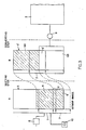
- FIG. 1 a block diagram illustrating the components of the present invention is shown. It is to be noted throughout the ensuing discussion that the components pictured do not correspond to any specific piece or pieces of hardware. The pictured components may also encompass more than one piece of hardware components. Those skilled in the art, however, will easily be able to design specific devices from the following necessarily general description.
- memory 3 of a computing device stores a document in compact format.
- the compact format of the document is partially shown as elements 4A, 4B, 4C and 4D.
- Element 4A and 4C are shown to be portions of the text of the document while elements 4B and 4D are shown to be portions of the graphics of the document.
- the compact representation is shown to be in sections to emphasize that the particular storage methods of each machine will vary and the storage format of any particular machine may divide the document into portions for storage efficiency.
- the document may have interleaved portions of text and graphics in both a vertical and horizontal sense, and the portions of the compact representation may divide in this manner.
- the compact format includes character and graphic arrays stored in structured format.
- a portion of cache 5 of the document is stored in bitmap image format.
- the display window of the document is defined as that portion of the document to be displayed on the display 1.
- the display window 6 resides completely within the portion of the document in the bitmap image 5.
- the display window 6, residing completely within the bitmap image has the same number of rows 2′ as the number of scan lines 2 of the display 1.
- the display window is marked with display marker 7 which may be moved up or down in increments of one row 2′ of the bitmap image by input device 10.
- At least part of the display window 6 as marked by display marker 7 is outputted to display hardware 8.
- the cache is typically stored in a raster buffer.
- At least the line 2′ of the display window 6 which corresponds to line 2 of the display 1 being physically scanned is outputted to a storage region of the display hardware 8.
- the display hardware converts the intensity encoder signals of the bitmap image into electronic signals which are recognized by the display element intensity controller. Often a number of lines 2′ below the current line 2 being physically scanned are stored in a number of line buffers in the display hardware 8. These buffers are reloaded from the bitmap image as the scan progresses.
- the display element intensity controller for a standard CRT for example, is the intensity controller of the electron gun.
- the cache 5 is created by rasterizor 9 accessing the appropriate portions of the document in memory 3, converting from compact format into bitmap image format, and loading the bitmap image 5.
- the display 1 and display hardware 8 of Figure 1 may, for example, consist of an IBM Video Gate Array (VGA) attached to a PS/2 monochrome display.
- the cache 5 may be stored in an IBM PC 64K byte memory segment. The entire document, stored in compact format, may reside in multiple IBM PC 64K memory segments, used in structured application.
- the compact format itself may be, for example, a single font text format or a multiple font text format.
- the function of the rasterizor 9 is that of a realtime document formatter.
- the initial display window 6 resides completely within the bitmap image 5 as defined by the position of display marker 7.
- This display window 6 corresponds to the portion of the document seen on display 1.
- the display marker 7 is then moved by input device 10 such that the final display window 6′, shown by dashed lines, also resides completely within the bitmap image 5.
- This display window 6′ then corresponds to the portion of the document seen on display 1.
- the system may have additional capability to allow the user to "jump” to a desired portion of the document by using the input device 10. This would move the display marker to the final display window 6′ without moving between intervening lines 2′.
- the change on the display would be a discrete change between the initial and final display window rather than a scrolled change.
- the user may "jump" from an initial display window within the cache to a final display window outside the cache, in which case adjustment of the cache will occur as described below so that the desired display window is encompassed within the cache.
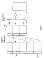
- Figures 3 and 4 demonstrate the present invention when the display marker 7 is moved such that some or all of the display window 6′ of the portion of the document to be displayed is not within the bitmap image. It is empha sized that this is a relatively unusual event since the user will normally be interested in scrolling within a small region of the document completely encompassed by the cache, as in Figure 2. When this occurs, the scroll on the display 1 is necessarily interrupted as the bitmap image is adjusted to contain a new cache which completely includes the display window 6′ of the portion of the document to be displayed.
- the display marker 7 is shown at an initial position defining initial display window 6, shown by solid line boundaries, and at a final position defining final display window 6′, shown by broken line boundaries.
- Display marker 7 is again moved by input device 10.
- the movement of display marker 7 to final display window 6′ may be by the input device 10 in "scroll” mode or "jump” mode.
- final display window 6′ lies partially within and partially without bitmap image 5.
- the output to display intensity controller 8 is insufficient to fill display 1.
- display marker 7 does not actually move outside the bitmap image 5 as shown in Figure 3.
- a counter in the system not shown in the Figures, which keeps track of the number of lines below the cache the display marker has been moved and, consequently, the relationship between the present cache and the final display window and, thus, the new display area within the document.
- Figure 3 is representative of the relative position of the portion of the document to be displayed with respect to the present cache when the display marker 7 moves to the extreme of the bitmap image 5.
- the display marker 7 and the final display window 6′ are shown as imaginary extensions, show by broken lines, of the bitmap image 5′. In the hardware, however, the relative position s are maintained by the counter.
- the display may "freeze” the last complete display window at the extrema of the cache, while the adjustment step occurs as described below. If the input device is in "jump” mode, the display may "freeze” the initial display window of the cache while adjustment occurs.
- the cache is adjusted as illustrated in Figure 3 so that the bitmap image 5 contains complete final display window 6′.
- the bitmap image 5 is shown to be adjusted at B so that the final display window 6′ lies in the center of the cache.
- two discretionary fringes 6A, 6B of the cache above and below the final display window 6′ have an equal number of rows.
- the dashed lines between the bitmap image 5 shown at A before adjustment of the cache shows the spatial relationship between the same portion of the document stored in the bitmap image 5 before and after adjustment. It is seen that the shaded portion at the bottom of the cache in bitmap image A appears at the top of the cache in bitmap image B after the adjustment step.
- the first step of the adjustment process consists of moving any usable portion of the present cache to the opposite side of the cache.
- the usable portion of he cache is defined as that portion of the cache present in the bitmap image 5 before adjustment which appears in the cache after the adjustment.
- the usable portion of the cache depends on the position of the final display window 6′ and the sizes of the discretionary fringes above 6A and below 6B the final display window 6′ after adjustment.
- Figure 4 demonstrates a relatively large scroll or jump where the top of the final display window 6′ at A is scrolled beneath the bottom of the bitmap image 5 by a number of rows greater than the discretionary fringe 6A above the final display window 6′ at B. It is seen by the dashed lines showing relative positions between the portions of the cache at A and the cache at B that none of the present cache at A appears in the post-adjustment cache at B; therefore, there is no usable portion as a result of the relatively large scroll.
- the usable portion is always written from one end of the cache to the other in order to move the final display window, located partially or completely outside the cache, into the cache after the adjustment step.
- the usable portion is that portion of the adjusted cache which is located at the opposite end. If the scroll were to the top end of the bitmap image 5 in Figure 3, the usable portion would be written to the bottom of the bitmap image 5 in the first adjustment step.
- the writing of the usable portion from one end of the bitmap image to the other may be accomplished row by row starting by writing the row of the usable portion opposite the border of the bitmap image to the opposite border of the bitmap image.
- the hardware to accomplish this step is not represented in the figures.
- the purpose of shifting the usable portion of the present cache in the first adjustment step is to avoid repeated rasterization of the usable portion, an unnecessarily slow process.
- the next step of the adjustment process consists of filling the remainder of the bitmap image 5′, the unshaded portion at B, with the remainder of the cache beneath the usable portion.
- the appropriate portion of the compact representation of the document in memory 3 is accessed, rasterized into bitmap image format by rasterizor 9 and loaded into bitmap image 5′.
- FIG 3 it is seen at B that the portion of the cache corresponding to part of the final display window 6′ and the complete lower discretionary fringe 6B loaded into the bitmap image 5′ at B by the rasterizor 9 in this step.
- the rasterization step can, of course, completely supplant the shifting step. Such is the case in Figure 4, where there is no usable portion of the initial cache.
- the complete final cache is therefore loaded into the bitmap image 5′ at B by the rasterizor 9. While a scroll or jump of this magnitude would be the worst case in terms of response time, such a change will be relatively rare, as described above. Furthermore, occasional prolonged response time, as in this case, is the result of storing less than the complete document in bitmap format, and thus reducing the interactive memory requirements.
- rasterizor In order to "know” the appropriate portions of the compact representation to rasterize, rasterizor must have an input derived from the counter, described above, the sizes of the discretionary fringes and the size of the cache which either directly inform rasterizor which portions of the compact memory need to be converted to "fill in” the cache, or allow the rasterizor to determine those portions.
- the rasterizor while performing a relatively simple conceptual step in the present invention, performs a numb er of complex steps on a hardware level to carry out that step.
- the rasterizor encompasses a portion of the CPU of the computer, since it must address and access the compact memory, and a portion of the display subsystem, since it converts the compact memory into the bitmap image format appropriate for the display.
- the POLITE "blocks" of text, graphics, image and use promotive functions such as character generators, line drawers and generators to produce bitmap output.
- the final step of the adjustment process is moving display marker 7 to mark display window 6′ of the newly adjusted cache. This step is shown completed at B in Figures 3 and 4.
- the outcome of the adjusting step in Figures 3 and 4 at B is a cache in the bitmap image 5′ with the display window 6′ of the portion of the document to be displayed in the center of the bitmap image 5′.
- smooth scrolling may be achieved between display windows completely within the cache. as in Figure 2.
- the three steps of the adjusting process may occur in any order in approximately an equivalent amount of time.
- the rasterizor may be converting the compact format and loading portions of the bitmap image at the same time the usable portion of the cache is being shifted.
- variable discretionary fringes which may be changed by the user depending on his requirements.
- a zero top discretionary fringe would be desirable, since the user will be scrolling continuously downward through the cache. This would reduce adjustment cycles since the lower discretionary fringe would be larger.
- the display marker 7 has been moved out of the cache, as in Figure 3. Until that point, the viewed scroll is smooth. Rather than continuing the scroll on the display before the adjustment process, which would simply scroll the last full display window of the cache partly or fully off the screen, the display would continue to output the last full display window at the bottom of the cache. This would only be reduced if the scroll were such that the usable portion of the cache became less than the last full display window, in which case only the usable portion would be displayed. After the complete rasterization step, or after each line of the step, the display would be "filled in” or moved line by line until the final display window appeared on the display.
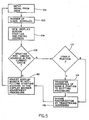
- the algorithm may be controlled by a program stored in the microprocessor of a computer which is executed each time a scroll input is received from the user.
- the algorithm is initiated upon an input signal from the user 100 which corresponds to a scroll.
- the scroll signal may be a digitally encoded signal which corresponds to the displacement of the input device, for example.
- the particular input depends on the input device used for scrolling in the particular machine. Whichever one is chosen, the particular signal for vertical scrolling must be determined from the device's reference document and the microprocessor translates the input signal into the number of lines in the bitmap image which is scrolled 102.
- the scroll can correlate to more lines than are available in the bitmap image. This corresponds to scrolling into the "imaginary" portion of the bitmap image as in Figures 3 and 4. In this case the determination of the number of lines scrolled 102 by the microprocessor will exceed the number above or below the current display window of the bitmap image.
- the starting and ending addresses of the new display window 104 in the bitmap image are determined. If the bitmap image addresses are consecutively numbered, the new starting address is determined by multiplying the number of lines scrolled by the number of display elements per line, and adding the product to the current bitmap window starting address. The specifics of the particular bitmap storage medium must be considered in this step. If the scroll exceeds the number of lines above or below the current display, the starting or ending address or both may be outside the bitmap image.
- the algorithm determines if the new display window resides completely in the current cache 108.
- the new display's bitmap starting and ending addresses are compared with the starting and ending addresses of the bitmap image itself or the "actual" bitmap image. If both addresses of the new display fall within the actual addresses of the bitmap image, the algorithm simply moves the display marker by outputting the starting and ending address to the display marker adjustment procedure 110.
- Adjustment of the display marker of a bitmap image by inputting new bitmap image addresses is dependent on the bitmap medium and supporting hardware and software. This step corresponds to "normal" scrolling completely within a bitmap image and may be implemented in numerous different ways available commercially and/or well documented in the art. See, for example, Foley and Van Dam, Fundamentals of Interactive Computer Graphics (Addison Wesley).
- the algorithm of the present invention must at this junction invoke the particular adjustment routine and hand off the appropriate data for adjustment, be it bitmap addresses or some equivalent.
- the algorithm of the present invention determines that the starting and/or ending bitmap address of the new display window is not within the actual bitmap image, whether there is a usable portion of the cache is then determined 112. If either the starting or ending bitmap address of the new display is in the actual bitmap image, then there is a usable portion. This situation corresponds to Figure 3. If both the starting and ending bitmap addresses of the new display are outside the actual bitmap image, then there may or may not be a usable portion.
- the usable portion determination 112 may be accomplished by subtracting the address width of the upper discretionary fringe from the starting bitmap address of the new display and determining if it lies within the actual bitmap addresses.
- the "address width" of the discretionary fringe is defined as the difference between the starting and ending bitmap addresses of the discretionary fringe. If there is a usable portion in this instance, it corresponds to the portion of the image between the address obtained by the above-cited subtraction, and the ending address of the actual bitmap image.
- the usable portion determination 112 may be accomplished by adding the address width of the lower discretionary fringe to the ending bitmap address of the new display and determining if it lies within the actual bitmap addresses. If there is a usable portion in this instance, it corresponds to the portion of the image between the beginning address of the actual bitmap image and the address of obtained by the above-cited addition.
- the microprocessor invokes a block shift routine of the bitmap image.
- the address of the usable portion and the starting and ending addresses of the actual bitmap image are used by the routine to shift each row of the usable portion to the opposite end of the bitmap image.
- the block shift routine algorithms are numerous and well documented. Commercial embodiments are widely available and documented and may be adapted for use by the algorithm of the present invention by handing off the appropriate addresses corresponding to the bitmap memory to be shifted and the area in the bitmap memory it is to be shifted to.
- bitmap block shift For algorithms describing bitmap block shift, see, for example, the Foley and Van Dam text, cited supra. Block shifting of a bitmap image is also utilized in a prior art device, the PERQ Mini-Computer, manufactured by Three Rivers Computer Co. and is described in the supporting technical documents.
- bitmap addresses corresponding thereto are first determined bases on the bitmap starting and ending addresses of the new display window and the sizes of the discretionary fringes.
- the bitmap addresses of the portion required to be rasterized will necessarily lie outside the actual bitmap addresses.
- bitmap addresses are passes off to the rasterization procedure where they are correlated to the compact memory addresses based on the compact memory addresses of the current cache in the bitmap image.
- the compact memory is rasterized and loaded serially into either the complete bitmap image or the portion above or below the shifted usable portion.
- the correlation step may take place in the rasterization algorithm.
- Rasterization algorithms including correlation features, are documented in Pazlidis, Algorithms for Graphics and Image Processing (Computer Science Press).
- the rasterizor must ultimately have the target compact memory addresses, but with correlation the bitmap addresses of the portion to be rasterized and the compact addresses of the orignal cache in the bitmap image enable the compact memory addresses to be determined.
Landscapes
- Engineering & Computer Science (AREA)
- Physics & Mathematics (AREA)
- Computer Hardware Design (AREA)
- General Physics & Mathematics (AREA)
- Theoretical Computer Science (AREA)
- Digital Computer Display Output (AREA)
- Controls And Circuits For Display Device (AREA)
Applications Claiming Priority (2)
| Application Number | Priority Date | Filing Date | Title |
|---|---|---|---|
| US07/367,434 US5053761A (en) | 1989-06-16 | 1989-06-16 | Method for smooth bitmap scrolling |
| US367434 | 1994-12-29 |
Publications (3)
| Publication Number | Publication Date |
|---|---|
| EP0403416A2 true EP0403416A2 (de) | 1990-12-19 |
| EP0403416A3 EP0403416A3 (de) | 1991-10-16 |
| EP0403416B1 EP0403416B1 (de) | 1996-09-04 |
Family
ID=23447150
Family Applications (1)
| Application Number | Title | Priority Date | Filing Date |
|---|---|---|---|
| EP90480077A Expired - Lifetime EP0403416B1 (de) | 1989-06-16 | 1990-05-29 | Datenspeicherhierarchie zur gleichmässigen Verschiebung eines Bitmap-Bildes |
Country Status (4)
| Country | Link |
|---|---|
| US (1) | US5053761A (de) |
| EP (1) | EP0403416B1 (de) |
| JP (1) | JPH0816836B2 (de) |
| DE (1) | DE69028353T2 (de) |
Cited By (5)
| Publication number | Priority date | Publication date | Assignee | Title |
|---|---|---|---|---|
| EP0516233A1 (de) * | 1991-05-31 | 1992-12-02 | Philips Electronique Grand Public | Vorrichtung zum Darstellen von Teilansichten eines Bildes |
| GB2308536A (en) * | 1995-12-21 | 1997-06-25 | Mitsubishi Electric Corp | A window display apparatus which moves display frames and a data processing system using this apparatus |
| FR2846115A1 (fr) * | 2002-10-16 | 2004-04-23 | Canal Plus Technologies | Procede d'affichage d'un document sur un ecran de visualisation susceptible d'etre soumis a une procedure de defilement |
| CN100423080C (zh) * | 2002-07-08 | 2008-10-01 | 汤姆森许可贸易公司 | 管理文档的当前部分在屏幕上的显示的单元和方法 |
| CN110109844A (zh) * | 2014-03-27 | 2019-08-09 | 英特尔公司 | 分布式图形处理器分级中的系统一致性 |
Families Citing this family (19)
| Publication number | Priority date | Publication date | Assignee | Title |
|---|---|---|---|---|
| US5526128A (en) * | 1989-06-19 | 1996-06-11 | Matsushita Electric Industrial Co., Ltd. | Image producing apparatus with memory unit having an image memory area of changeable storage capacity |
| DE69206796T2 (de) * | 1991-04-24 | 1997-02-13 | Michael Sussman | Digitale dokumentenvergroesserungsvorrichtung |
| JPH05158459A (ja) * | 1991-12-03 | 1993-06-25 | Pioneer Electron Corp | 画像表示制御装置 |
| US5774134A (en) * | 1993-12-10 | 1998-06-30 | Fujitsu Limited | Graphic display device having function of displaying transfer area |
| US7322011B2 (en) * | 1994-01-06 | 2008-01-22 | Microsoft Corporation | System and method of adjusting display characteristics of a displayable data file using an ergonomic computer input device |
| US5473344A (en) * | 1994-01-06 | 1995-12-05 | Microsoft Corporation | 3-D cursor positioning device |
| US6940488B1 (en) | 1994-01-06 | 2005-09-06 | Microsoft Corporation | System and method of adjusting display characteristics of a displayable data file using an ergonomic computer input device |
| DE4405330A1 (de) * | 1994-02-21 | 1995-08-24 | Vobis Microcomputer Ag | Verfahren zum Scrollen von mehreren Rasterzeilen in einem Fenster eines Grafikmodus betriebenen Bildschirms eines Personalcomputers |
| US5530455A (en) * | 1994-08-10 | 1996-06-25 | Mouse Systems Corporation | Roller mouse for implementing scrolling in windows applications |
| JPH08146941A (ja) * | 1994-11-18 | 1996-06-07 | Pioneer Electron Corp | 画像表示装置 |
| US6067068A (en) * | 1996-04-16 | 2000-05-23 | Canon Business Machines, Inc. | Scrollable display window |
| US6745368B1 (en) * | 1999-06-11 | 2004-06-01 | Liberate Technologies | Methods, apparatus, and systems for storing, retrieving and playing multimedia data |
| US7038664B2 (en) * | 2001-11-01 | 2006-05-02 | Fellowes, Inc. | Input device for scrolling a computer display |
| US7660512B2 (en) * | 2003-10-16 | 2010-02-09 | Microsoft Corporation | Systems and methods for managing frame rates during multimedia playback |
| EP1690433B1 (de) * | 2003-11-12 | 2008-04-30 | Research In Motion Limited | Datenfähige netzwerkprioritäten mit verringerten verzögerungen in einem datendienst |
| US7681141B2 (en) * | 2004-05-11 | 2010-03-16 | Sony Computer Entertainment America Inc. | Fast scrolling in a graphical user interface |
| US9223771B2 (en) * | 2008-09-30 | 2015-12-29 | Apple Inc. | Locking spreadsheet cells |
| JP2014110597A (ja) * | 2012-12-04 | 2014-06-12 | Canon Inc | 画像処理装置、プレビュー画像表示方法、及びプログラム |
| JP6834118B2 (ja) * | 2015-02-16 | 2021-02-24 | 富士通株式会社 | 端末装置、画面更新プログラム、画面更新方法及び情報処理システム |
Family Cites Families (14)
| Publication number | Priority date | Publication date | Assignee | Title |
|---|---|---|---|---|
| JPS6014356B2 (ja) * | 1979-03-05 | 1985-04-12 | 日本電信電話株式会社 | 画像表示装置 |
| US4412294A (en) * | 1981-02-23 | 1983-10-25 | Texas Instruments Incorporated | Display system with multiple scrolling regions |
| US4437093A (en) * | 1981-08-12 | 1984-03-13 | International Business Machines Corporation | Apparatus and method for scrolling text and graphic data in selected portions of a graphic display |
| JPS5938791A (ja) * | 1982-08-30 | 1984-03-02 | 株式会社東芝 | 画像表示装置 |
| JPS5942413A (ja) * | 1982-09-01 | 1984-03-09 | Hitachi Ltd | 車両用走行位置表示装置 |
| DE3373233D1 (en) * | 1983-09-28 | 1987-10-01 | Ibm | Data display apparatus with character refresh buffer and bow buffers |
| IT1162945B (it) * | 1983-09-30 | 1987-04-01 | Olivetti & Co Spa | Apparecchiatura di visualizzazione di immagini definite da una pluralita di righe di dati |
| US4611202A (en) * | 1983-10-18 | 1986-09-09 | Digital Equipment Corporation | Split screen smooth scrolling arrangement |
| US4663617A (en) * | 1984-02-21 | 1987-05-05 | International Business Machines | Graphics image relocation for display viewporting and pel scrolling |
| JPS60205580A (ja) * | 1984-03-30 | 1985-10-17 | オークマ株式会社 | 動画処理方法 |
| JPS61209485A (ja) * | 1985-03-14 | 1986-09-17 | 富士通株式会社 | 画像表示装置 |
| JPS61267788A (ja) * | 1985-05-23 | 1986-11-27 | 東京電力株式会社 | 図形表示装置 |
| US4815012A (en) * | 1986-02-05 | 1989-03-21 | Allied-Signal Inc. | Apparatus and method for real time reconstruction of digital map data |
| JPS62197900A (ja) * | 1986-02-25 | 1987-09-01 | 沖電気工業株式会社 | 地図情報表示方法及び装置 |
-
1989
- 1989-06-16 US US07/367,434 patent/US5053761A/en not_active Expired - Fee Related
-
1990
- 1990-05-16 JP JP2126528A patent/JPH0816836B2/ja not_active Expired - Lifetime
- 1990-05-29 EP EP90480077A patent/EP0403416B1/de not_active Expired - Lifetime
- 1990-05-29 DE DE69028353T patent/DE69028353T2/de not_active Expired - Fee Related
Cited By (9)
| Publication number | Priority date | Publication date | Assignee | Title |
|---|---|---|---|---|
| EP0516233A1 (de) * | 1991-05-31 | 1992-12-02 | Philips Electronique Grand Public | Vorrichtung zum Darstellen von Teilansichten eines Bildes |
| FR2677206A1 (fr) * | 1991-05-31 | 1992-12-04 | Philips Electro Grand Public | Dispositif pour visualiser des vues partielles d'une image. |
| GB2308536A (en) * | 1995-12-21 | 1997-06-25 | Mitsubishi Electric Corp | A window display apparatus which moves display frames and a data processing system using this apparatus |
| GB2308536B (en) * | 1995-12-21 | 1998-06-03 | Mitsubishi Electric Corp | A window display apparatus which moves display frames and a data processing system using this apparatus |
| CN100423080C (zh) * | 2002-07-08 | 2008-10-01 | 汤姆森许可贸易公司 | 管理文档的当前部分在屏幕上的显示的单元和方法 |
| FR2846115A1 (fr) * | 2002-10-16 | 2004-04-23 | Canal Plus Technologies | Procede d'affichage d'un document sur un ecran de visualisation susceptible d'etre soumis a une procedure de defilement |
| WO2004035702A3 (fr) * | 2002-10-16 | 2004-07-22 | Canal Plus Technologies | Ecran de visualisation susceptible d'etre soumis a une procedure de defilement. |
| US7796142B2 (en) | 2002-10-16 | 2010-09-14 | Thomson Licensing S.A. | Display screen capable of being subjected to a scroll procedure |
| CN110109844A (zh) * | 2014-03-27 | 2019-08-09 | 英特尔公司 | 分布式图形处理器分级中的系统一致性 |
Also Published As
| Publication number | Publication date |
|---|---|
| EP0403416A3 (de) | 1991-10-16 |
| DE69028353D1 (de) | 1996-10-10 |
| JPH0816836B2 (ja) | 1996-02-21 |
| DE69028353T2 (de) | 1997-03-13 |
| JPH0394296A (ja) | 1991-04-19 |
| US5053761A (en) | 1991-10-01 |
| EP0403416B1 (de) | 1996-09-04 |
Similar Documents
| Publication | Publication Date | Title |
|---|---|---|
| EP0403416B1 (de) | Datenspeicherhierarchie zur gleichmässigen Verschiebung eines Bitmap-Bildes | |
| US6172669B1 (en) | Method and apparatus for translation and storage of multiple data formats in a display system | |
| US4947342A (en) | Graphic processing system for displaying characters and pictures at high speed | |
| US5815168A (en) | Tiled memory addressing with programmable tile dimensions | |
| EP0737956B1 (de) | Bildspeicher für graphische Daten | |
| JPH06214550A (ja) | コンピュータの出力表示のためのフレームバッファメモリを提供する装置および方法 | |
| CN87100869A (zh) | 显示处理器 | |
| US6078306A (en) | Basic input-output system (BIOS) read-only memory (ROM) with capability for vertical scrolling of bitmapped graphic text by columns | |
| US4570161A (en) | Raster scan digital display system | |
| US4667306A (en) | Method and apparatus for generating surface-fill vectors | |
| US5291188A (en) | Method and apparatus for allocating off-screen display memory | |
| KR860001450B1 (ko) | 그래픽 디스플레이 시스템 | |
| JPS6261092A (ja) | 表示装置 | |
| EP0118255A2 (de) | Graphische Anzeigeeinheit | |
| US6281876B1 (en) | Method and apparatus for text image stretching | |
| JPH07113818B2 (ja) | オペレータが選択した像部分の表示方法及び装置 | |
| KR960003396B1 (ko) | 모니터 제어회로 | |
| EP0062669B1 (de) | Grafik- und text-bildgenerator für eine rasterabtastanzeige | |
| US5371513A (en) | Apparatus for generating programmable interrupts to indicate display positions in a computer | |
| US5870074A (en) | Image display control device, method and computer program product | |
| US4649379A (en) | Data display apparatus with character refresh buffer and row buffers | |
| US4646262A (en) | Feedback vector generator for storage of data at a selectable rate | |
| JP4107517B2 (ja) | Xyマップメモリを用いた部分的ポリゴン描画方法 | |
| US4703230A (en) | Raster operation circuit | |
| EP0146594B1 (de) | Verfahren und vorrichtung zum erzeugen von vektorattributen |
Legal Events
| Date | Code | Title | Description |
|---|---|---|---|
| PUAI | Public reference made under article 153(3) epc to a published international application that has entered the european phase |
Free format text: ORIGINAL CODE: 0009012 |
|
| AK | Designated contracting states |
Kind code of ref document: A2 Designated state(s): DE FR GB |
|
| 17P | Request for examination filed |
Effective date: 19901213 |
|
| PUAL | Search report despatched |
Free format text: ORIGINAL CODE: 0009013 |
|
| AK | Designated contracting states |
Kind code of ref document: A3 Designated state(s): DE FR GB |
|
| 17Q | First examination report despatched |
Effective date: 19931019 |
|
| GRAH | Despatch of communication of intention to grant a patent |
Free format text: ORIGINAL CODE: EPIDOS IGRA |
|
| GRAH | Despatch of communication of intention to grant a patent |
Free format text: ORIGINAL CODE: EPIDOS IGRA |
|
| GRAA | (expected) grant |
Free format text: ORIGINAL CODE: 0009210 |
|
| AK | Designated contracting states |
Kind code of ref document: B1 Designated state(s): DE FR GB |
|
| REF | Corresponds to: |
Ref document number: 69028353 Country of ref document: DE Date of ref document: 19961010 |
|
| ET | Fr: translation filed | ||
| PLBE | No opposition filed within time limit |
Free format text: ORIGINAL CODE: 0009261 |
|
| STAA | Information on the status of an ep patent application or granted ep patent |
Free format text: STATUS: NO OPPOSITION FILED WITHIN TIME LIMIT |
|
| 26N | No opposition filed | ||
| PG25 | Lapsed in a contracting state [announced via postgrant information from national office to epo] |
Ref country code: FR Free format text: LAPSE BECAUSE OF NON-PAYMENT OF DUE FEES Effective date: 19980130 |
|
| REG | Reference to a national code |
Ref country code: FR Ref legal event code: ST |
|
| PGFP | Annual fee paid to national office [announced via postgrant information from national office to epo] |
Ref country code: GB Payment date: 20000427 Year of fee payment: 11 |
|
| PG25 | Lapsed in a contracting state [announced via postgrant information from national office to epo] |
Ref country code: GB Free format text: LAPSE BECAUSE OF NON-PAYMENT OF DUE FEES Effective date: 20010529 |
|
| PGFP | Annual fee paid to national office [announced via postgrant information from national office to epo] |
Ref country code: DE Payment date: 20010914 Year of fee payment: 12 |
|
| GBPC | Gb: european patent ceased through non-payment of renewal fee |
Effective date: 20010529 |
|
| PG25 | Lapsed in a contracting state [announced via postgrant information from national office to epo] |
Ref country code: DE Free format text: LAPSE BECAUSE OF NON-PAYMENT OF DUE FEES Effective date: 20021203 |