EP0403127A1 - Automatische Gangwechsel-Steuereinrichtung für Kraftfahrzeuge und Verfahren zur Steuerung - Google Patents
Automatische Gangwechsel-Steuereinrichtung für Kraftfahrzeuge und Verfahren zur Steuerung Download PDFInfo
- Publication number
- EP0403127A1 EP0403127A1 EP90305985A EP90305985A EP0403127A1 EP 0403127 A1 EP0403127 A1 EP 0403127A1 EP 90305985 A EP90305985 A EP 90305985A EP 90305985 A EP90305985 A EP 90305985A EP 0403127 A1 EP0403127 A1 EP 0403127A1
- Authority
- EP
- European Patent Office
- Prior art keywords
- engine
- gear
- load
- automobile
- automatic transmission
- Prior art date
- Legal status (The legal status is an assumption and is not a legal conclusion. Google has not performed a legal analysis and makes no representation as to the accuracy of the status listed.)
- Granted
Links
- 230000008859 change Effects 0.000 title claims abstract description 39
- 238000000034 method Methods 0.000 title claims abstract description 14
- 230000005540 biological transmission Effects 0.000 claims abstract description 57
- 238000002485 combustion reaction Methods 0.000 claims abstract description 8
- 230000035939 shock Effects 0.000 description 19
- 239000000446 fuel Substances 0.000 description 4
- 238000010586 diagram Methods 0.000 description 3
- 230000000694 effects Effects 0.000 description 2
- 230000009467 reduction Effects 0.000 description 2
- 230000001360 synchronised effect Effects 0.000 description 2
- 230000001133 acceleration Effects 0.000 description 1
- 230000009471 action Effects 0.000 description 1
- 238000010276 construction Methods 0.000 description 1
- 238000013016 damping Methods 0.000 description 1
- 230000007246 mechanism Effects 0.000 description 1
- SYHGEUNFJIGTRX-UHFFFAOYSA-N methylenedioxypyrovalerone Chemical compound C=1C=C2OCOC2=CC=1C(=O)C(CCC)N1CCCC1 SYHGEUNFJIGTRX-UHFFFAOYSA-N 0.000 description 1
- 238000002360 preparation method Methods 0.000 description 1
- 230000002035 prolonged effect Effects 0.000 description 1
- 230000004044 response Effects 0.000 description 1
- 239000004065 semiconductor Substances 0.000 description 1
- 239000000725 suspension Substances 0.000 description 1
- 238000004804 winding Methods 0.000 description 1
Images


Classifications
-
- B—PERFORMING OPERATIONS; TRANSPORTING
- B60—VEHICLES IN GENERAL
- B60K—ARRANGEMENT OR MOUNTING OF PROPULSION UNITS OR OF TRANSMISSIONS IN VEHICLES; ARRANGEMENT OR MOUNTING OF PLURAL DIVERSE PRIME-MOVERS IN VEHICLES; AUXILIARY DRIVES FOR VEHICLES; INSTRUMENTATION OR DASHBOARDS FOR VEHICLES; ARRANGEMENTS IN CONNECTION WITH COOLING, AIR INTAKE, GAS EXHAUST OR FUEL SUPPLY OF PROPULSION UNITS IN VEHICLES
- B60K31/00—Vehicle fittings, acting on a single sub-unit only, for automatically controlling vehicle speed, i.e. preventing speed from exceeding an arbitrarily established velocity or maintaining speed at a particular velocity, as selected by the vehicle operator
-
- F—MECHANICAL ENGINEERING; LIGHTING; HEATING; WEAPONS; BLASTING
- F16—ENGINEERING ELEMENTS AND UNITS; GENERAL MEASURES FOR PRODUCING AND MAINTAINING EFFECTIVE FUNCTIONING OF MACHINES OR INSTALLATIONS; THERMAL INSULATION IN GENERAL
- F16H—GEARING
- F16H61/00—Control functions within control units of change-speed- or reversing-gearings for conveying rotary motion ; Control of exclusively fluid gearing, friction gearing, gearings with endless flexible members or other particular types of gearing
- F16H61/04—Smoothing ratio shift
- F16H61/0403—Synchronisation before shifting
-
- B—PERFORMING OPERATIONS; TRANSPORTING
- B60—VEHICLES IN GENERAL
- B60W—CONJOINT CONTROL OF VEHICLE SUB-UNITS OF DIFFERENT TYPE OR DIFFERENT FUNCTION; CONTROL SYSTEMS SPECIALLY ADAPTED FOR HYBRID VEHICLES; ROAD VEHICLE DRIVE CONTROL SYSTEMS FOR PURPOSES NOT RELATED TO THE CONTROL OF A PARTICULAR SUB-UNIT
- B60W10/00—Conjoint control of vehicle sub-units of different type or different function
- B60W10/04—Conjoint control of vehicle sub-units of different type or different function including control of propulsion units
- B60W10/06—Conjoint control of vehicle sub-units of different type or different function including control of propulsion units including control of combustion engines
-
- B—PERFORMING OPERATIONS; TRANSPORTING
- B60—VEHICLES IN GENERAL
- B60W—CONJOINT CONTROL OF VEHICLE SUB-UNITS OF DIFFERENT TYPE OR DIFFERENT FUNCTION; CONTROL SYSTEMS SPECIALLY ADAPTED FOR HYBRID VEHICLES; ROAD VEHICLE DRIVE CONTROL SYSTEMS FOR PURPOSES NOT RELATED TO THE CONTROL OF A PARTICULAR SUB-UNIT
- B60W10/00—Conjoint control of vehicle sub-units of different type or different function
- B60W10/10—Conjoint control of vehicle sub-units of different type or different function including control of change-speed gearings
- B60W10/11—Stepped gearings
-
- B—PERFORMING OPERATIONS; TRANSPORTING
- B60—VEHICLES IN GENERAL
- B60W—CONJOINT CONTROL OF VEHICLE SUB-UNITS OF DIFFERENT TYPE OR DIFFERENT FUNCTION; CONTROL SYSTEMS SPECIALLY ADAPTED FOR HYBRID VEHICLES; ROAD VEHICLE DRIVE CONTROL SYSTEMS FOR PURPOSES NOT RELATED TO THE CONTROL OF A PARTICULAR SUB-UNIT
- B60W30/00—Purposes of road vehicle drive control systems not related to the control of a particular sub-unit, e.g. of systems using conjoint control of vehicle sub-units
- B60W30/18—Propelling the vehicle
- B60W30/19—Improvement of gear change, e.g. by synchronisation or smoothing gear shift
-
- B—PERFORMING OPERATIONS; TRANSPORTING
- B60—VEHICLES IN GENERAL
- B60W—CONJOINT CONTROL OF VEHICLE SUB-UNITS OF DIFFERENT TYPE OR DIFFERENT FUNCTION; CONTROL SYSTEMS SPECIALLY ADAPTED FOR HYBRID VEHICLES; ROAD VEHICLE DRIVE CONTROL SYSTEMS FOR PURPOSES NOT RELATED TO THE CONTROL OF A PARTICULAR SUB-UNIT
- B60W2540/00—Input parameters relating to occupants
- B60W2540/16—Ratio selector position
-
- B—PERFORMING OPERATIONS; TRANSPORTING
- B60—VEHICLES IN GENERAL
- B60W—CONJOINT CONTROL OF VEHICLE SUB-UNITS OF DIFFERENT TYPE OR DIFFERENT FUNCTION; CONTROL SYSTEMS SPECIALLY ADAPTED FOR HYBRID VEHICLES; ROAD VEHICLE DRIVE CONTROL SYSTEMS FOR PURPOSES NOT RELATED TO THE CONTROL OF A PARTICULAR SUB-UNIT
- B60W2710/00—Output or target parameters relating to a particular sub-units
- B60W2710/06—Combustion engines, Gas turbines
- B60W2710/0644—Engine speed
-
- B—PERFORMING OPERATIONS; TRANSPORTING
- B60—VEHICLES IN GENERAL
- B60W—CONJOINT CONTROL OF VEHICLE SUB-UNITS OF DIFFERENT TYPE OR DIFFERENT FUNCTION; CONTROL SYSTEMS SPECIALLY ADAPTED FOR HYBRID VEHICLES; ROAD VEHICLE DRIVE CONTROL SYSTEMS FOR PURPOSES NOT RELATED TO THE CONTROL OF A PARTICULAR SUB-UNIT
- B60W2710/00—Output or target parameters relating to a particular sub-units
- B60W2710/10—Change speed gearings
- B60W2710/1005—Transmission ratio engaged
-
- F—MECHANICAL ENGINEERING; LIGHTING; HEATING; WEAPONS; BLASTING
- F16—ENGINEERING ELEMENTS AND UNITS; GENERAL MEASURES FOR PRODUCING AND MAINTAINING EFFECTIVE FUNCTIONING OF MACHINES OR INSTALLATIONS; THERMAL INSULATION IN GENERAL
- F16H—GEARING
- F16H61/00—Control functions within control units of change-speed- or reversing-gearings for conveying rotary motion ; Control of exclusively fluid gearing, friction gearing, gearings with endless flexible members or other particular types of gearing
- F16H61/04—Smoothing ratio shift
- F16H61/0403—Synchronisation before shifting
- F16H2061/0411—Synchronisation before shifting by control of shaft brakes
Definitions
- This invention relates to an automatic gear change control apparatus for an automobile and a method of controlling such apparatus, and more particularly to an automatic gear change control apparatus capable of reducing a shock (jolt) due to a gear change (gear shift) and a method of controlling such apparatus.
- Japanese Unexamined Patent Publication No. 55-69738 discloses an automatic gear change control apparatus in which a jolt (gear-change shock) control-starting speed (n1nA) and a terminating speed (n1nE) are calculated from the rotational speed of the engine obtained when starting the gear shifting, and the output torque is controlled during a period when the rotational speed of the engine actually changes from the speed n1nA to the speed n1nE.
- a jolt (gear-change shock) control-starting speed (n1nA) and a terminating speed (n1nE) are calculated from the rotational speed of the engine obtained when starting the gear shifting, and the output torque is controlled during a period when the rotational speed of the engine actually changes from the speed n1nA to the speed n1nE.
- a method of controlling a gear change of an automobile comprising an internal combustion engine; an automatic transmission connected to an output rotation shaft of the engine so as to transmit the rotational output of the engine to drive wheels of the automobile through any selected one of a plurality of gear ratios; a load device selectively connectable to the output rotation shaft of the engine via selectively-connecting means; and means for generating a gear change control signal for selecting one of the gear ratios of the automatic transmission in accordance with one of operational conditions of the automobile and the engine; the method comprising the steps of: controlling the selectively-connecting means when the gear change signal-generating means generates the control signal for shifting up the gear in the automatic transmission, in such a manner that the selectively-connecting means connects the load device to the output rotation shaft of the engine.
- an automatic gear change control apparatus for an automobile, the automobile comprising an internal combustion engine; an automatic transmission connected to an output rotation shaft of the engine so as to transmit the rotational output of the engine to drive wheels of the automobile through any selected one of a plurality of gear ratios; the apparatus comprising: a load device for applying a load; means for connecting the load device to the output rotation shaft of the engine and for generating a gear change control signal for selecting one of the gear ratios of the automatic transmission in accordance with one of operational conditions of the automobile and the engine; and load control means for increasing the load of the load device when the gear change signal-generating means generates the control signal for shifting up the gear in the automatic transmission.
- the rotational output of the internal combustion engine is transmitted to the drive wheels of the automobile via the automatic transmission, and also the rotational output of the internal combustion engine is connected to the load device.
- the load of the load device is increased, or the load device is connected to the output rotation shaft of the engine via the selectively-connecting means.
- the rotational speed of the output rotation shaft of the engine is rapidly lowered or reduced to a required level by the energy-absorbing action of the load device, so that the rotational speeds of the opposite side of the cluth, connected to the gear of the automatic transmission, are made equal to each other, thereby achieving the gear shifting (gear change) without causing a shock.
- Fig. 1 is a block diagram of the first embodiment according to the present invention
- Fig. 2 is a block diagram of the second embodiment according to the present invention
- Fig. 3 is a block diagram of the third embodiment according to the present invention
- Fig. 4 is diagramatic view of the third embodiment according to the present invention
- Fig. 5 is diagramatic view of the fifth embodiment according to the present invention
- Fig. 6 is a time chart explanatory of the operation of each of the above control apparatuses of the invention.
- Fig. 1 shows an automatic gear change control apparatus for an automobile according to a first embodiment of the present invention.
- An engine 1 of the automobile includes an output rotation shaft 101.
- the rotation output exerted on the output rotation shaft 101 of the engine 1 is inputted into an automatic transmission 2, and is also connected to a load device 4 via a load-applying clutch 3.
- the output of the automatic transmission 2 is also connected via its output shaft and a differential device 5 to drive wheels 6 for propelling the automobile.
- a common form of the automatic transmission 2 comprises planetary gears and hydraulic clutches, and these are schematically shown as a plurality of gears 7 to 9 having respective reduction ratios of 1/n1 to 1/nm and clutches 11 to nm for connecting these gears to the output shaft 10.
- a transmission control device 14 outputs a shift control signal SP to the automatic transmission 2 so as to control the gear shifting of the automatic transmission 2.
- a running speed (vehicle speed) V of the automobile, a throttle opening degree L representative of the engine load, and etc. are inputted to the transmission control device 14.
- the transmission control device 14 outputs a load-applying signal LD for controlling the operation (engagement and disengagement) of the load-applying clutch 3 so as to apply the load, and an engine control signal PD for controlling the output of the engine 1.
- the clutch 12 is to be engaged.
- a difference between the rotational speeds of the opposite sides of the clutch 12 is (1/n2 - 1/n1) ⁇ N since the rotational speed of the input side of the clutch 12 is N1/n2.
- the clutch 12 is engaged in this condition, a gear-change shock (jolt) occurs. Therefore, when the engine rotational speed N is lowered to N2 which is equal to (n2/n1) ⁇ N1, the rotational speed of the input side of the clutch 12 is N2/n2 which is equal to N1/n1.
- the rotational speed of the input side of the clutch 12 becomes equal to the rotational speed of the output side thereof, thereby preventing a gear-change shock or jolt. Since this sequential operation is carried out in a short shfit-up time of about 0.5 seconds, the rotational speed N of the engine 1 is also required to rapidly change from N1 to N2 in such a short time of about 0.5 seconds.
- the engine 1 can not recover the rotational energy, stored in the moment of inertia possessed by the engine itself, in a fuel system serving as an energy source. Therefore, although the engine output can be lowered by a stop of fuel supply or the adjustment of an ignition timing (specifically, the shifting of the ignition timing to the delay side), it is impossible, only with such means, to rapidly lower the engine rotational speed without wasting the rotational energy so far stored.
- the transmission control device 14 outputs the shift control signal SP, representing the shifting-up of the gear from a first to a second position, so as to disengage the clutch 11, and at the same time outputs the load-applying signal LD and the engine control signal PD as described above.
- the load-applying signal LD changes the load-applying clutch 3 from a disengaged condition to an engaged condition so as to connect the load device 4 to the output rotation shaft 101 of the engine 1.
- the load device 4 should be of the type which can be intermittently operated without any problem and can apply a load proportional to the engine speed.
- Examples of such type are a compressor for an air conditioner, and an air compressor for controlling a suspension.
- the pressure increases in proportion to the engine speed, and therefore the load torque is substantially proportional to the engine speed, and desirable results can be obtained.
- the angular velocity of the rotation of the engine 1 is ⁇ 1
- a compressor for an air condition is suited for this purpose.
- the above engine control signal reduces the outout of the engine 1, for example, by temporarily stopping the operation of the injector to stop the supply of fuel to the engine 1, or by temporarily closing the throttle valve to temporarily delay the ignition timing.
- a generator for charging a battery is used as a load device.
- an output rotation shaft 101 of an engine 1 is directly connected at one end to an input shaft of an automatic transmission 2a, and there is not provided a load-applying clutch for connecting and disconnecting the output rotation shaft 101 of the engine relative to the load device.
- a pulley 102 is mounted on the other end of the output rotation shaft 101 of the engine 1, and a belt 103 is extended around the pulley 102 and a pulley 104.
- the output rotation shaft 101 is adapted to normally drive or rotate a rotor of the generator 15 via the pulleys 102 and 104 and the belt 103, the generator 15 serving to charge the battery 15.
- a regulator 17 controls the electric power generated by the generator 15.
- the regulator 17 receives a load-applying signal LD from a transmission control device 14a similar to that of the preceding embodiment of Fig. 1, and outputs a generation control signal GCS to the generator 15 so as to control the generation of electric power.
- the transmission control device 14a when the gear of the automatic transmission 2a is to be shifted up, the transmission control device 14a outputs a shift control signal SP to disengage a clutch 11 of the automatic transmission 2a, and also outputs the load-applying signal LD to the regulator 17.
- the regulator 17 normally controls the generator 15 (for example, field winding current or the like of the generator 15) so as to charge the battery 16 at a constant voltage.
- Such increased portion of the electric power is so predetermined as to correspond to the engine rotational speed N obtained when starting the shfiting-up, and causes the rotational speeds of the opposite sides of the clutch (for example, the clutch 12 in Fig. 1) in the automatic transmission 2a to become equal to each other during a gear-change time of about 0.5 seconds. More specifically, the rotational speed of the output rotation shaft 101 of the engine 1 is lowered to meet the rotational speed of the output side of the clutch. As a result, the amount of generation of electric power of the generator 15 is increased, and therefore a larger charge current flows into the battery 16. However, this time period is very short on the order of about 0.5 seconds as described above, and therefore there is particularly no problem.
- the transmission control device 14a feeds an instruction for engaging, for example, the 2nd-speed clutch 12 (Fig. 1), thus completing the shifting-up from the 1st-speed position to the 2nd-speed position.
- the transmission control device 14a is further provdided with an engine rotation sensor 50 for detecting the engine rotational speed N, a vehicle speed sensor 51 for detecting the running speed of the automobile.
- the transmission control device 14a can calculate the optimum load torque from these detected values obtained at the time of starting the gear change. Further, since the battery voltage VB and the rotational frequency NG of the generator are inputted into the regulator 17, it is possible to calculate a generator-energizing current required for producing the above optimum load torque.
- the optimum load torque can be produced depending on the speed to which the gear is changed, and therefore the gear change involving only a small shock can always be effected even when the point of the gear change is varied depending on the circumstances of the running of the automobile.
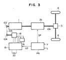
- Fig. 3 shows a third embodiment of the invention.
- a generator-motor 18 which is originally provided for absorbing vibrations produced when an engine 1 is idling. In this embodiment, it is intended to relieve or reduce a gear-change shock, utilizing the generator-motor 18. More specifically, upon receipt of a damping signal from a damper control unit 19, the generator-motor 18 functions as a generator to convert a rotational output energy of the engine 1 into electric power so as to absorb it. In contrast, the generator-motor 18 also functions as an electric motor so as to apply rotational energy to the engine 1 via pulleys 102 and 104 and a belt 103.
- the damper control unit 19 prevents mechanical vibrations of the engine 1 due to lowering or irregularity of a combustion cycle.
- a bi-directional semi-condcutor converter circuit is incorporated in the damper control unit 19.
- this bi-directional semi-conductor converter circuit causes the generator-motor 18 to function as an electric motor, and at this time, depending on whether this electric motor is a dc motor or an ac motor, this converter circuit functions as a chopper or an inverter for converting the battery voltage.
- the above converter circuit when absorbing the rotational output energy of the engine 1, the above converter circuit causes the generator-motor 18 to function as a generator, and at this time time converter circuit functions as a step-up chopper or a converter for recovering the generated electric power in the battery 16.
- the converter circuit When the converter circuit can not fully recover the generated electric power in the battery 16, the converter circuit causes a load resistor 20 to consume the energy.
- the damper control unit 19 can freely supply and absorb the energy via the generator-motor 18, and therefore the opposite ends of the clutch can be synchronized with each other accurately and rapidly, thereby positively eliminating a gear-change shock.
- the damper control unit 19 is used only when the engine 1 is idling, and is not necessary during the running of the automobile.
- the efficiency of use of the damper control unit 19 is advantageously enhanced.
- a transmission control device 14b outputs a shift control signal SP to disengage a clutch (not shown) in an automatic transmission 2b.
- the transmission control device 14b outputs a load-applying signal LD to the damper control unit 19.
- the load-applying signal LD is not a mere ON/OFF signal, but is representative of the value of the load torque T calculated from the engine rotational speed N, obtained immediately before the gear change, in accordance with the above formula (3), and is also representative of a time period t at the end of which the engagement of the next clutch is completed.
- the damper control unit 19 Upon receipt of the load-applying signal LD, the damper control unit 19 controls the current of the generator-motor 18 in such a manner that the torque T is applied to the engine 1 for the time period t.
- a target value (represented by the angular velocity ⁇ 2) of the rotational frequency of the engine may be given so that the control is effected until the engine rotational frequency actually reaches this target value.
- the above time period t should be not more than 0.5 seconds.
- Fig. 4 shows a fourth embodiment of the invention.
- a brake device is mounted directly on an input shaft 20 of an automatic transmission 2c connected to an output rotation shaft 101 of an engine 1.
- the automatic transmission 2c is different in construction from the automatic transmission of Fig. 1 having the plurality of parallel gears of reduction ratios n1 to nm.
- the internal structure of the automatic transmission 2c is cross-sectionally shown in Fig. 4. More specifically, as is clear from Fig. 4, the automatic transmission 2c employs a plurality of planetary gears, and constitutes three to four forward gears and one reverse gear with a small number of component parts.
- the output of the engine 1 is inputted to the automatic transmission 2c via the output rotation shaft 101, and within the automatic transmission 2c, the engine output is further transmitted via a torque converter 21 and the input shaft 20 thereof to rotate a sun gear 23 in mesh with planetary gears 22 of a rear train.
- the planetary gears 22 are connected to an output shaft 10C, and also are connected to an internal gear 27 in mesh with planetary gears 25 of a front train so as to rotate therewith.
- An internal gear 24 of the rear train is engageable with the planetary gears 25 of the front train via a forward one-way clutch 28, a forward clutch 29 and an overrun clutch 30.
- the planetary gears 25 of the front train can be fixed to a speed of zero by a low-and-reverse brake 31 and a low one-way clutch 32, and also can be coupled to an output shaft of the torque converter 21 via a high clutch 33.
- a sun gear 26 of the front train can be coupled to the output shaft of the torque converter 21 via a reverse clutch 34, and also can be fixed to a speed of zero by a brake band 35.
- the automatic transmission carries out the gear change by selectively connecting and fixing the elements of the two sets of planetary gears by the four clutches, the two brakes and the two one-way clutches.
- a shift-up brake 36 is additionally provided. More specifically, when the gear shifting-up is to be effected, a transmission control device 14c feeds, to a hydraulic control portion 37, an instruction SP for disengaging the clutch now engaged.
- the transmission control device 14c feeds an instruction LD to a hydraulic valve 38 to abruptly operate the shift-up brake 36. Then, when the rotational speed of the input shaft 20 of the torque converter 21 is lowered to an appropriate value, the shift-up brake 36 is loosened, and the next clutch is slowly engaged.
- the braking force of the shift-up brake 36 (that is, the pressure of the hydraulic valve 38) is programmed to be applied for each gear-shifting stage so that the above sequential control can be carried out within 0.5 seconds.
- the optimum braking force can be applied for each gear-shifting stage of the automatic transmission, and therefore the gear-change shock can be always kept to a minimum.
- the load is not applied directly to the engine 1, but is applied thereto via the torque converter 21. Therefore, advantageously, the abrupt braking during the gear shifting is alleviated by the torque converter 21, and an undue load is not applied to the engine 1.
- Fig. 5 shows a fifth embodiment of the invention. A mechanism portion of this embodiment is cross-sectionally shown as in Fig. 4.
- the output of an engine 1 is connected to an automatic transmission 2d, and the rotational energy of the engine 1 can also be applied to a flywheel 40 intermediate the engine 1 and the automatic transmission 2d via a clutch 39.
- a transmission control device 14d feeds a shift control signal SP so as to disengage a clutch now engaged within the automatic transmission 2d.
- the transmission control device 14d feeds a load-applying signal LD to a flywheel control portion 41 for controlling the flywheel 40.
- the flywheel control portion 41 engages the clutch 39, and t the same time loosens a brake 42.
- the inertia energy stored in the rotational portion of the engine 1 is consumed to operate the flywheel 40, so that the output rotational speed of the engine 1 is abruptly lowered, thereby reducing a gear-change shock.
- the load-applying signal LD is caused to stop, and as a result the flywheel control portion 41 disengages the clutch 39, and operates the brake 42 to stop the flywheel 40 in preparation for the next gear shifting-up.
- the clutch 39 and the brake 42 may be of either the electromagnetic type or the hydraulic type, and depending on it, the flywheel control portion 41 employs either an electromagnetic solenoid or an electromagnetic valve.
- the above method of this embodiment does not utilize the load produced by the originally-provided component part of the automobile, and therefore the load-applying portion can always wait for its operation in a stationary condition, and can apply the load when this is required.
- the gear change time t1 can be sufficiently shorter than 0.5 seconds. Therefore, though the magnitude of the energy to be absorbed differs depending on the vehicle speed, this can be dealt with by adjusting the gear change time t1.
- the gear change can be effected during the constant gear change time t1.
Landscapes
- Engineering & Computer Science (AREA)
- Chemical & Material Sciences (AREA)
- Combustion & Propulsion (AREA)
- Mechanical Engineering (AREA)
- Transportation (AREA)
- General Engineering & Computer Science (AREA)
- Automation & Control Theory (AREA)
- Control Of Transmission Device (AREA)
- Control Of Vehicle Engines Or Engines For Specific Uses (AREA)
- Control Of Driving Devices And Active Controlling Of Vehicle (AREA)
Applications Claiming Priority (2)
| Application Number | Priority Date | Filing Date | Title |
|---|---|---|---|
| JP1146806A JPH0314736A (ja) | 1989-06-12 | 1989-06-12 | 自動車の自動変速制御装置及びその制御方式 |
| JP146806/89 | 1989-06-12 |
Publications (2)
| Publication Number | Publication Date |
|---|---|
| EP0403127A1 true EP0403127A1 (de) | 1990-12-19 |
| EP0403127B1 EP0403127B1 (de) | 1994-08-31 |
Family
ID=15415952
Family Applications (1)
| Application Number | Title | Priority Date | Filing Date |
|---|---|---|---|
| EP90305985A Expired - Lifetime EP0403127B1 (de) | 1989-06-12 | 1990-06-01 | Automatische Gangwechsel-Steuereinrichtung für Kraftfahrzeuge und Verfahren zur Steuerung |
Country Status (5)
| Country | Link |
|---|---|
| US (1) | US5031479A (de) |
| EP (1) | EP0403127B1 (de) |
| JP (1) | JPH0314736A (de) |
| KR (1) | KR910000414A (de) |
| DE (1) | DE69011973T2 (de) |
Cited By (5)
| Publication number | Priority date | Publication date | Assignee | Title |
|---|---|---|---|---|
| DE4122628A1 (de) * | 1991-07-09 | 1993-01-14 | Renk Ag | Getriebeanlage |
| DE19627895C1 (de) * | 1996-07-11 | 1998-02-19 | Daimler Benz Ag | Zahnräderwechselgetriebe |
| FR2792263A1 (fr) * | 1999-04-16 | 2000-10-20 | Luk Lamellen & Kupplungsbau | Dispositif d'actionnement automatise d'un embrayage et/ou d'une boite de vitesses de vehicule automobile |
| CN103419776A (zh) * | 2012-05-25 | 2013-12-04 | 罗伯特·博世有限公司 | 具有再生系统的车辆 |
| WO2017162372A1 (de) * | 2016-03-24 | 2017-09-28 | Voith Patent Gmbh | Integrierte läuferbremse |
Families Citing this family (9)
| Publication number | Priority date | Publication date | Assignee | Title |
|---|---|---|---|---|
| US6203468B1 (en) * | 1998-11-18 | 2001-03-20 | Fuji Jukogyo Kabushiki Kaisha | Control device for hybrid vehicle and method thereof |
| JP4199456B2 (ja) * | 2000-03-10 | 2008-12-17 | 株式会社日立製作所 | 自動変速機及びその制御装置 |
| US6642688B1 (en) * | 2002-05-22 | 2003-11-04 | Errol E. Wallingford | Throttle and AC motor control throughout shifts of multi-speed transmissions |
| JP4365431B2 (ja) | 2007-08-10 | 2009-11-18 | トヨタ自動車株式会社 | 車両および駆動装置並びにそれらの制御方法 |
| WO2011114367A1 (ja) * | 2010-03-16 | 2011-09-22 | トヨタ自動車株式会社 | 車両の制御装置 |
| CN104685261B (zh) * | 2012-07-24 | 2018-03-23 | Dti集团有限公司 | 传动系统 |
| JP6065446B2 (ja) * | 2012-08-02 | 2017-01-25 | いすゞ自動車株式会社 | 車両の制御装置 |
| US11808225B1 (en) * | 2022-09-01 | 2023-11-07 | Caterpillar Inc. | Engine load control during a transient event |
| US11662005B1 (en) * | 2022-09-15 | 2023-05-30 | GM Global Technology Operations LLC | Electric vehicle drive system with reversible torque converter |
Citations (8)
| Publication number | Priority date | Publication date | Assignee | Title |
|---|---|---|---|---|
| US4266447A (en) * | 1978-11-09 | 1981-05-12 | Robert Bosch Gmbh | Apparatus and method for improving the jolt control in a motor vehicle drive system |
| DE3142713A1 (de) * | 1981-10-28 | 1983-05-05 | Robert Bosch Gmbh, 7000 Stuttgart | Verfahren zum steuern von stufengetrieben in kraftfahrzeugen |
| DE3151252A1 (de) * | 1980-07-15 | 1983-07-07 | Robert Bosch Gmbh, 7000 Stuttgart | Verfahren zur beeinflussung einer brennkraftmaschine |
| US4403527A (en) * | 1979-09-06 | 1983-09-13 | Robert Bosch Gmbh | Apparatus for decreasing jolts during gear shifts in automatic transmissions in motor vehicles |
| DE3542146A1 (de) * | 1984-11-28 | 1986-06-05 | Honda Giken Kogyo K.K., Tokio/Tokyo | Steuerungssystem fuer ein maschinenangetriebenes zusatzgeraet fuer fahrzeuge |
| US4667540A (en) * | 1984-02-24 | 1987-05-26 | Nissan Motor Co., Ltd. | Shift shock alleviating apparatus and method for automatic transmission |
| US4691285A (en) * | 1983-12-21 | 1987-09-01 | Nissan Motor Co., Ltd. | Method and apparatus for alleviating transmission shift shocks |
| AT388340B (de) * | 1982-06-01 | 1989-06-12 | Klampfl Herbert Ing | Vorrichtung zur ausnuetzung der brems- und leerlaufenergie in kraftfahrzeugen |
Family Cites Families (10)
| Publication number | Priority date | Publication date | Assignee | Title |
|---|---|---|---|---|
| DE388340C (de) * | 1924-01-11 | Jahn & Teilhaber | Krautausreisser fuer Kartoffelerntemaschinen | |
| GB1362808A (en) * | 1970-12-31 | 1974-08-07 | Nissan Motor | Fuel injection system incorporating shift shock preventing device |
| IT939884B (it) * | 1971-09-25 | 1973-02-10 | Fiat Spa | Cambio a sincronizzazione elettroni ca particolarmente per autoveicoli |
| US4838124A (en) * | 1986-06-30 | 1989-06-13 | Toyota Jidosha Kabushiki Kaisha | System for integrally controlling automatic transmission and engine |
| JPS63306939A (ja) * | 1987-06-10 | 1988-12-14 | Mazda Motor Corp | エンジンのトルク制御装置 |
| JPS644544A (en) * | 1987-06-26 | 1989-01-09 | Aisin Aw Co | Speed change control device for automobile |
| JP2691404B2 (ja) * | 1987-08-12 | 1997-12-17 | ヤンマーディーゼル株式会社 | 作業車輌の制御装置 |
| JPS6482660A (en) * | 1987-09-25 | 1989-03-28 | Fujitsu Ltd | Lead frame |
| JPH0684135B2 (ja) * | 1987-09-29 | 1994-10-26 | ジャトコ株式会社 | エンジン・自動変速機駆動系統の制御装置 |
| DE58905512D1 (de) * | 1988-07-01 | 1993-10-14 | Volkswagen Ag | Verfahren zur Drehzahlsynchronisation. |
-
1989
- 1989-06-12 JP JP1146806A patent/JPH0314736A/ja active Pending
-
1990
- 1990-06-01 DE DE69011973T patent/DE69011973T2/de not_active Expired - Fee Related
- 1990-06-01 EP EP90305985A patent/EP0403127B1/de not_active Expired - Lifetime
- 1990-06-04 US US07/532,673 patent/US5031479A/en not_active Expired - Fee Related
- 1990-06-11 KR KR1019900008516A patent/KR910000414A/ko not_active IP Right Cessation
Patent Citations (8)
| Publication number | Priority date | Publication date | Assignee | Title |
|---|---|---|---|---|
| US4266447A (en) * | 1978-11-09 | 1981-05-12 | Robert Bosch Gmbh | Apparatus and method for improving the jolt control in a motor vehicle drive system |
| US4403527A (en) * | 1979-09-06 | 1983-09-13 | Robert Bosch Gmbh | Apparatus for decreasing jolts during gear shifts in automatic transmissions in motor vehicles |
| DE3151252A1 (de) * | 1980-07-15 | 1983-07-07 | Robert Bosch Gmbh, 7000 Stuttgart | Verfahren zur beeinflussung einer brennkraftmaschine |
| DE3142713A1 (de) * | 1981-10-28 | 1983-05-05 | Robert Bosch Gmbh, 7000 Stuttgart | Verfahren zum steuern von stufengetrieben in kraftfahrzeugen |
| AT388340B (de) * | 1982-06-01 | 1989-06-12 | Klampfl Herbert Ing | Vorrichtung zur ausnuetzung der brems- und leerlaufenergie in kraftfahrzeugen |
| US4691285A (en) * | 1983-12-21 | 1987-09-01 | Nissan Motor Co., Ltd. | Method and apparatus for alleviating transmission shift shocks |
| US4667540A (en) * | 1984-02-24 | 1987-05-26 | Nissan Motor Co., Ltd. | Shift shock alleviating apparatus and method for automatic transmission |
| DE3542146A1 (de) * | 1984-11-28 | 1986-06-05 | Honda Giken Kogyo K.K., Tokio/Tokyo | Steuerungssystem fuer ein maschinenangetriebenes zusatzgeraet fuer fahrzeuge |
Cited By (5)
| Publication number | Priority date | Publication date | Assignee | Title |
|---|---|---|---|---|
| DE4122628A1 (de) * | 1991-07-09 | 1993-01-14 | Renk Ag | Getriebeanlage |
| DE19627895C1 (de) * | 1996-07-11 | 1998-02-19 | Daimler Benz Ag | Zahnräderwechselgetriebe |
| FR2792263A1 (fr) * | 1999-04-16 | 2000-10-20 | Luk Lamellen & Kupplungsbau | Dispositif d'actionnement automatise d'un embrayage et/ou d'une boite de vitesses de vehicule automobile |
| CN103419776A (zh) * | 2012-05-25 | 2013-12-04 | 罗伯特·博世有限公司 | 具有再生系统的车辆 |
| WO2017162372A1 (de) * | 2016-03-24 | 2017-09-28 | Voith Patent Gmbh | Integrierte läuferbremse |
Also Published As
| Publication number | Publication date |
|---|---|
| JPH0314736A (ja) | 1991-01-23 |
| KR910000414A (ko) | 1991-01-29 |
| DE69011973D1 (de) | 1994-10-06 |
| EP0403127B1 (de) | 1994-08-31 |
| US5031479A (en) | 1991-07-16 |
| DE69011973T2 (de) | 1995-03-23 |
Similar Documents
| Publication | Publication Date | Title |
|---|---|---|
| US5031479A (en) | Automatic gear change control apparatus for automobile and method of controlling same | |
| US6569055B2 (en) | Four-wheel drive hybrid vehicle | |
| US7676313B2 (en) | Target speed control strategy for power-off shifts in a hybrid electric vehicle | |
| US7223201B2 (en) | Control of power-on downshifts in a multiple-ratio powertrain for a hybrid vehicle | |
| CN1275790C (zh) | 动力传动系统 | |
| JP3952005B2 (ja) | ハイブリッド車両の駆動装置 | |
| US6692402B2 (en) | Drive control apparatus for oil pump | |
| US4495836A (en) | Automotive vehicle power drive system | |
| US20070205735A1 (en) | Control device for a hybrid electric vehicle | |
| JP3227905B2 (ja) | 電気モータ駆動車輌 | |
| JP2000224714A (ja) | 電動機付車両 | |
| JPS6032063B2 (ja) | 車輛用自動変速機の制御方法 | |
| JPH06174067A (ja) | 自動車用の自動変速機と動力伝達系統装置 | |
| JPH11348603A (ja) | ハイブリッド車両の制御装置 | |
| DE19953587A1 (de) | Steuerung für Überbrückungskupplung | |
| KR20090019724A (ko) | 차량의 가속 쇼크 경감 장치 | |
| US9791043B2 (en) | Control device of a powertrain with a centrifugal pendulum damper | |
| JP3450980B2 (ja) | デューティサイクル型ソレノイド弁の制御方法および装置 | |
| WO2000003163A1 (en) | Arrangement and method for a driving unit in a vehicle | |
| JP2004516999A (ja) | 動力系の制御および調整方法 | |
| US5081887A (en) | System and method for controlling vehicle speed to prevent gear shift shock applicable to automatic transmission equipped vehicles | |
| JP3852403B2 (ja) | ハイブリッド駆動装置の制御装置 | |
| JP2004208473A (ja) | 車両の振動抑制制御 | |
| JP3633409B2 (ja) | 内燃機関の間欠運転機能を有する車両およびその車両に用いられる始動制御装置 | |
| JP2003294123A (ja) | パラレルハイブリッド車両 |
Legal Events
| Date | Code | Title | Description |
|---|---|---|---|
| PUAI | Public reference made under article 153(3) epc to a published international application that has entered the european phase |
Free format text: ORIGINAL CODE: 0009012 |
|
| 17P | Request for examination filed |
Effective date: 19900625 |
|
| AK | Designated contracting states |
Kind code of ref document: A1 Designated state(s): DE FR GB |
|
| 17Q | First examination report despatched |
Effective date: 19921127 |
|
| GRAA | (expected) grant |
Free format text: ORIGINAL CODE: 0009210 |
|
| AK | Designated contracting states |
Kind code of ref document: B1 Designated state(s): DE FR GB |
|
| REF | Corresponds to: |
Ref document number: 69011973 Country of ref document: DE Date of ref document: 19941006 |
|
| ET | Fr: translation filed | ||
| PLBE | No opposition filed within time limit |
Free format text: ORIGINAL CODE: 0009261 |
|
| STAA | Information on the status of an ep patent application or granted ep patent |
Free format text: STATUS: NO OPPOSITION FILED WITHIN TIME LIMIT |
|
| 26N | No opposition filed | ||
| PGFP | Annual fee paid to national office [announced via postgrant information from national office to epo] |
Ref country code: FR Payment date: 19990318 Year of fee payment: 10 |
|
| PG25 | Lapsed in a contracting state [announced via postgrant information from national office to epo] |
Ref country code: FR Free format text: LAPSE BECAUSE OF NON-PAYMENT OF DUE FEES Effective date: 20010228 |
|
| REG | Reference to a national code |
Ref country code: FR Ref legal event code: ST |
|
| REG | Reference to a national code |
Ref country code: GB Ref legal event code: IF02 |
|
| PGFP | Annual fee paid to national office [announced via postgrant information from national office to epo] |
Ref country code: GB Payment date: 20020527 Year of fee payment: 13 |
|
| PGFP | Annual fee paid to national office [announced via postgrant information from national office to epo] |
Ref country code: DE Payment date: 20020628 Year of fee payment: 13 |
|
| PG25 | Lapsed in a contracting state [announced via postgrant information from national office to epo] |
Ref country code: GB Free format text: LAPSE BECAUSE OF NON-PAYMENT OF DUE FEES Effective date: 20030601 |
|
| PG25 | Lapsed in a contracting state [announced via postgrant information from national office to epo] |
Ref country code: DE Free format text: LAPSE BECAUSE OF NON-PAYMENT OF DUE FEES Effective date: 20040101 |
|
| GBPC | Gb: european patent ceased through non-payment of renewal fee |
Effective date: 20030601 |