EP0401529A1 - Gas turbine combustion chamber - Google Patents
Gas turbine combustion chamber Download PDFInfo
- Publication number
- EP0401529A1 EP0401529A1 EP90108684A EP90108684A EP0401529A1 EP 0401529 A1 EP0401529 A1 EP 0401529A1 EP 90108684 A EP90108684 A EP 90108684A EP 90108684 A EP90108684 A EP 90108684A EP 0401529 A1 EP0401529 A1 EP 0401529A1
- Authority
- EP
- European Patent Office
- Prior art keywords
- combustion chamber
- burners
- burner
- premix burners
- air
- Prior art date
- Legal status (The legal status is an assumption and is not a legal conclusion. Google has not performed a legal analysis and makes no representation as to the accuracy of the status listed.)
- Granted
Links
Images


Classifications
-
- F—MECHANICAL ENGINEERING; LIGHTING; HEATING; WEAPONS; BLASTING
- F23—COMBUSTION APPARATUS; COMBUSTION PROCESSES
- F23R—GENERATING COMBUSTION PRODUCTS OF HIGH PRESSURE OR HIGH VELOCITY, e.g. GAS-TURBINE COMBUSTION CHAMBERS
- F23R3/00—Continuous combustion chambers using liquid or gaseous fuel
- F23R3/28—Continuous combustion chambers using liquid or gaseous fuel characterised by the fuel supply
- F23R3/30—Continuous combustion chambers using liquid or gaseous fuel characterised by the fuel supply comprising fuel prevapourising devices
-
- F—MECHANICAL ENGINEERING; LIGHTING; HEATING; WEAPONS; BLASTING
- F23—COMBUSTION APPARATUS; COMBUSTION PROCESSES
- F23D—BURNERS
- F23D11/00—Burners using a direct spraying action of liquid droplets or vaporised liquid into the combustion space
- F23D11/36—Details, e.g. burner cooling means, noise reduction means
- F23D11/40—Mixing tubes or chambers; Burner heads
- F23D11/402—Mixing chambers downstream of the nozzle
-
- F—MECHANICAL ENGINEERING; LIGHTING; HEATING; WEAPONS; BLASTING
- F23—COMBUSTION APPARATUS; COMBUSTION PROCESSES
- F23D—BURNERS
- F23D17/00—Burners for combustion conjointly or alternatively of gaseous or liquid or pulverulent fuel
- F23D17/002—Burners for combustion conjointly or alternatively of gaseous or liquid or pulverulent fuel gaseous or liquid fuel
-
- F—MECHANICAL ENGINEERING; LIGHTING; HEATING; WEAPONS; BLASTING
- F23—COMBUSTION APPARATUS; COMBUSTION PROCESSES
- F23R—GENERATING COMBUSTION PRODUCTS OF HIGH PRESSURE OR HIGH VELOCITY, e.g. GAS-TURBINE COMBUSTION CHAMBERS
- F23R3/00—Continuous combustion chambers using liquid or gaseous fuel
- F23R3/02—Continuous combustion chambers using liquid or gaseous fuel characterised by the air-flow or gas-flow configuration
- F23R3/04—Air inlet arrangements
- F23R3/10—Air inlet arrangements for primary air
- F23R3/12—Air inlet arrangements for primary air inducing a vortex
-
- F—MECHANICAL ENGINEERING; LIGHTING; HEATING; WEAPONS; BLASTING
- F23—COMBUSTION APPARATUS; COMBUSTION PROCESSES
- F23R—GENERATING COMBUSTION PRODUCTS OF HIGH PRESSURE OR HIGH VELOCITY, e.g. GAS-TURBINE COMBUSTION CHAMBERS
- F23R3/00—Continuous combustion chambers using liquid or gaseous fuel
- F23R3/28—Continuous combustion chambers using liquid or gaseous fuel characterised by the fuel supply
- F23R3/34—Feeding into different combustion zones
-
- F—MECHANICAL ENGINEERING; LIGHTING; HEATING; WEAPONS; BLASTING
- F23—COMBUSTION APPARATUS; COMBUSTION PROCESSES
- F23R—GENERATING COMBUSTION PRODUCTS OF HIGH PRESSURE OR HIGH VELOCITY, e.g. GAS-TURBINE COMBUSTION CHAMBERS
- F23R3/00—Continuous combustion chambers using liquid or gaseous fuel
- F23R3/42—Continuous combustion chambers using liquid or gaseous fuel characterised by the arrangement or form of the flame tubes or combustion chambers
- F23R3/50—Combustion chambers comprising an annular flame tube within an annular casing
-
- F—MECHANICAL ENGINEERING; LIGHTING; HEATING; WEAPONS; BLASTING
- F23—COMBUSTION APPARATUS; COMBUSTION PROCESSES
- F23C—METHODS OR APPARATUS FOR COMBUSTION USING FLUID FUEL OR SOLID FUEL SUSPENDED IN A CARRIER GAS OR AIR
- F23C2900/00—Special features of, or arrangements for combustion apparatus using fluid fuels or solid fuels suspended in air; Combustion processes therefor
- F23C2900/07002—Premix burners with air inlet slots obtained between offset curved wall surfaces, e.g. double cone burners
Definitions
- the present invention relates to a combustion chamber according to the preamble of claim 1.
- premix burners With regard to the prescribed, extremely low NO x emissions when operating a gas turbine, many manufacturers are adopting premix burners.
- One of the disadvantages of premix burners is that they extinguish at very low air numbers, depending on the temperature of the compressor of the gas turbine, at around 2. For this reason, such premix burners must be supported by one or more pilot burners in the partial load operation of a gas turbine. Diffusion burners are usually used for this.
- This technology enables very low No x emissions in the area of full load. In contrast, this auxiliary burner system leads at partial load operation at significantly higher NO x emissions.
- the invention seeks to remedy this.
- the invention as characterized in the claims, is based on the object of providing a combustion chamber which, with minimized exhaust gas emissions, enables a wide operating range, while optimizing the quality factor for the temperature profile at the turbine inlet, in the technical term "pattern factor".
- main burners are related to the small premix burners, hereinafter referred to as pilot burners, with regard to the flow through them
- the pilot burners work as independent premix burners in the entire load range of the combustion chamber, with the air ratio remaining almost constant. Because the pilot burners can now be operated in the entire load range with an ideal mixture (premix burner), the NO x emissions are very low even at partial load. It also shows that, in the interest of "up-prizing" potential for gas turbines with higher turbine inlet temperatures, the proportion of air that cannot be formed by the burners (lean blowoff limit, CO / UHC) is not, because of the pattern factor, should only be used for cooling purposes.
- a certain proportion of air is introduced via the air nozzles provided here, preferably after the primary combustion zone of the combustion chamber, and there it is ensured that perfect mixing takes place.
- This has the advantage that the proportion of air that ensures “up-rating” and is therefore blown directly into the secondary combustion zone prevents the undesirable "thinning" of the primary zone. Since the air nozzles are located at a point with a very low air velocity and only occupy a limited width of the front wall, their influence on the main flow field in the primary area is only very weak. In particular, the air nozzles do not interfere with the cross-ignition between primary burners and main burners. Another advantage of these air nozzles results from their position on the front wall; this zone would become very hot there without the cooling effect of the air jets.
- main burners and the pilot burners consist of so-called double-cone burners of different sizes, and if these are integrated in an annular combustion chamber. Because the circulating streamlines in the annular combustion chamber come very close to the vortex centers of the pilot burners in such a constellation, ignition is only possible with these pilot burners.
- the amount of fuel that is supplied via the pilot burner is increased until the pilot burner is activated, i.e. until the full amount of fuel is available.
- the configuration is chosen so that this point corresponds to the load shedding condition of the gas turbine.
- the further increase in output then takes place via the main burner.
- the main burners are also fully controlled at the peak load of the system.
- FIG. 1 shows a section of a sector of the front wall 10. This shows the placement of the individual main burners B and pilot burners C. These are evenly and alternately distributed over the circumference of the annular combustion chamber A.
- the size difference shown between main burners B and pilot burners C is only of a qualitative nature.
- the effective size of the individual burners and their distribution and number on the circumference of the front wall 10 of the annular combustion chamber A, as already explained above, depends on the power and size of the combustion chamber itself.
- the main burners B and pilot burners C which are arranged alternately, open out all at the same height in a uniform annular front wall 10, which forms the entry surface of the annular combustion chamber A.
- a number of air nozzles D are provided, which occupy approximately half the width of the front wall 10 in the radial direction.
- a circulating flow that surrounds the burners B and C is created above and below them.
- the role of the roles is here through the co-rotating burner taken over.
- a vortex center is also created around the respective burner; around the pilot burner C, the vortex centers are small and hot, and inherently unstable. These come to rest between the large, cooler vortex centers originating from the main burners B.
- the air nozzles F act, which decisively improve the stabilization of the two, as has already been appreciated in the foregoing. Even if the main burners B are operated lean, as is the case in part-load operation, a very good burnout with low CO / UHC emissions can be expected.
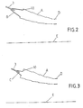
- FIGS. 2 and 3 show a schematic section through an annular combustion chamber A, respectively in the plane of a pilot burner C and. of a main burner B.
- the annular combustion chamber A shown here is tapered in the direction of the turbine inlet D, as can be seen from the central axis E of the annular combustion chamber A shown.
- An individual nozzle 3 is allocated to each burner B, C.
- the burners B, C are at the same time premix burners, that is to say they do without the otherwise usual premix zone.
- these premix burners B, C regardless of their specific design, must be designed in such a way that there is no fear of re-ignition into the premix zone via the respective front panel 10.
- a premix burner which excellently fulfills this condition is shown comprehensively in FIGS. 6-9 and explained in more detail there, the structure being able to be the same for both burner types (main burner B / pilot burner C), only their size will be different.
- the size ratio between main burner B and pilot burner C is selected such that about 23% of the burner air flows through the pilot burner C and about 77% through the main burner B.
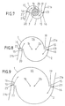
- FIG. 4 and 5 schematically show a main burner B, according to section IV-IV from FIG. 1, and the air nozzles F, according to section V-V from FIG. 1, in a positionally coordinated axial section.
- the structure for the air nozzles F which extends far into the combustion chamber with respect to the front wall 10 and which causes the air to act further downstream of the flame front of the burners B and C must be observed.
- FIGS. 7-9 are used simultaneously with FIG. 6. Furthermore, in order not to make FIG. 6 unnecessarily confusing, the guide plates 21a, 21b shown schematically according to FIGS. 7-9 have only been hinted at in it. In the following, the description of FIG. 6 will optionally refer to the remaining FIGS. 7-9 as required.
- the burner B / C according to FIG. 6, which can be both a pilot burner C and a main burner B in terms of structure, consists of two half-hollow partial cone bodies 1, 2 which are offset from one another.
- the offset of the respective central axis 1b, 2b of the partial cone bodies 1, 2 to each other creates a tangential air inlet slot 19, 20 on both sides in a mirror-image arrangement (FIGS. 7-9), through which the combustion air 15 enters the interior of the burner, ie flows into the cone cavity 14.
- the two partial cone bodies 1, 2 each have a cylindrical initial part 1a, 2a which is also analogous to that Partial cone bodies 1, 2 run offset from one another, so that the tangential air inlet slots 19, 20 are present from the beginning.
- a nozzle 3 is accommodated, the fuel injection 4 of which coincides with the narrowest cross section of the conical cavity 14 formed by the two partial cone bodies 1, 2.
- the size of this nozzle 3 depends on the type of burner, ie whether it is a pilot burner C or main burner B. Of course, the burner can be made purely conical, that is to say without cylindrical starting parts 1a, 2a.
- Both partial cone bodies 1, 2 each have a fuel line 8, 9, which are provided with openings 17 through which the gaseous fuel 13, which is mixed with the combustion air 15 flowing through the tangential air inlet slots 19, 20.
- the position of these fuel lines 8, 9 are provided at the end of the tangential air inlet slots 19, 20, so that the admixture 16 of this fuel 13 with the inflowing combustion air 15 also takes place there.
- the burner B / C has a plate which forms the front wall 10.
- the liquid fuel 12 flowing through the nozzle 3 is injected into the cone cavity 14 at an acute angle such that a cone-shaped fuel spray which is as homogeneous as possible occurs in the burner outlet plane.
- the fuel injector 4 can be an air-assisted nozzle or a pressure atomizer.
- it can also be a dual burner with gaseous and liquid fuel supply, as is described, for example, in EP-A1 210 462.
- the conical liquid fuel profile 5 from the nozzle 3 is enclosed by a rotating combustion air stream 15 flowing in tangentially.
- the concentration of the liquid fuel 12 is continuously reduced in the direction by the mixed-in combustion air 15. If gaseous fuel 13/16 is burned, the mixture is formed with the combustion air 15 directly at the end of the air inlet slots 19, 20.
- the optimal, homogeneous fuel concentration is in the area of the vortex bursting, that is to say in the area of the backflow zone 6 reached the cross section.
- the ignition takes place at the top of the return flow zone 6. Only at this point can a stable flame front 7 arise.
- the nitrogen oxide and carbon monoxide emissions are low if the excess air is at least 60%, which is one of them additional precaution to minimize NO x emissions is available.
- the pollutant emission values are lowest. The same also applies to near-stoichiometric operation when the excess air is replaced by recirculating exhaust gas.
- the design of the burner is particularly suitable for changing the size of the tangential air inlet slots 19, 20 for a given overall length of the burner by fixing the partial cone bodies 1, 2 to the end plate 10 by means of a releasable connection.
- the distance between the two central axes 1b, 2b decreases or increases as a result of radial displacement of the two partial cone bodies 1, 2 to and from one another, and the gap size of the tangential air inlet slots 19, 20 changes accordingly, as is particularly well shown in FIGS. 7-9 emerges.
- the partial cone bodies 1, 2 can also be displaced relative to one another in another plane, as a result of which even an overlap thereof can be controlled.
- 7-9 also shows the position of the guide plates 21a, 21b. They have flow introduction functions, whereby, depending on their length, they extend the respective end of the partial cone bodies 1 and 2 in the flow direction of the combustion air 15.
- the channeling of the combustion air into the cone cavity 14 can be optimized by opening or closing the guide plates 21a, 21b about the pivot point 23, in particular this is necessary if the original gap size of the tangential air inlet slots 19, 20 is changed.
- the burner can also be operated without baffles.
Abstract
Description
Die vorliegende Erfindung betrifft eine Brennkammer gemäss Oberbegriff des Anspruchs 1.The present invention relates to a combustion chamber according to the preamble of
Im Hinblick auf die vorgeschriebenen, extrem niedrige NOx-Emissionen beim Betrieb einer Gasturbine gehen viele Hersteller dazu über, Vormischbrenner einzusetzen. Einer der Nachteile von Vormischbrennern besteht darin, dass sie bereits bei sehr niedrigen Luftzahlen, je nach Temperatur nach dem Verdichter der Gasturbine bei einer von ca. 2, löschen. Aus diesem Grund müssen solche Vormischbrenner im Teillastbetrieb einer Gasturbine von einem oder mehreren Pilotbrennern gestützt werden. In der Regel werden hierfür Diffussionsbrenner eingesetzt. Diese Technik ermöglicht zwar sehr niedrige Nox-Emissionen im Bereich der Vollast. Demgegenüber führt dieses Stützbrennersystem bei Teillast betrieb zu wesentlich höheren NOx-Emissionen. Der verschiedentlich bekannt gewordene Versuch, die Diffusions-Stützbrenner magerer zu fahren oder kleinere Stützbrenner zu verwenden, muss daran scheitern, weil sich der Ausbrand verschlechtert und die C0/UHC-Emissionen sehr stark ansteigen. In der Fachsprache ist dieser Zustand unter der Bezeichnung CO/UHC-NOx-Schere bekannt geworden.With regard to the prescribed, extremely low NO x emissions when operating a gas turbine, many manufacturers are adopting premix burners. One of the disadvantages of premix burners is that they extinguish at very low air numbers, depending on the temperature of the compressor of the gas turbine, at around 2. For this reason, such premix burners must be supported by one or more pilot burners in the partial load operation of a gas turbine. Diffusion burners are usually used for this. This technology enables very low No x emissions in the area of full load. In contrast, this auxiliary burner system leads at partial load operation at significantly higher NO x emissions. The attempt, which has become known variously, to run the diffusion auxiliary burners leaner or to use smaller auxiliary burners must fail because the burnout deteriorates and the C0 / UHC emissions increase very sharply. In technical terms, this condition is known as CO / UHC-NO x scissors.
Hier will die Erfindung Abhilfe schaffen. Der Erfindung, wie sie in den Ansprüchen gekennzeichnet ist, liegt die Aufgabe zugrunde, eine Brennkammer bereitzustellen, welche bei minimierten Abgasemissionen einen breiten Betriebsbereich ermöglicht, unter Optimierung des Qualitätsfaktors für das Temperaturprofil am Turbineneintritt, in der Fachsprache "Pattern Factor" benannt.The invention seeks to remedy this. The invention, as characterized in the claims, is based on the object of providing a combustion chamber which, with minimized exhaust gas emissions, enables a wide operating range, while optimizing the quality factor for the temperature profile at the turbine inlet, in the technical term "pattern factor".
Dazu wird entlang der ganzen Frontwand der Brennkammer vorgesehen, abwechslungsweise einen grossen und einen kleinen Vormischbrenner zu plazieren, d.h. zwischen zwei grossen Vormischbrennern ist jeweils ein kleiner Vormischbrenner zu finden. Des weiteren werden jeweils zwischen einem grossen und einen kleinen Vormischbrenner Luftdüsen vorgesehen, welche einen gewissen Luftanteil in den Brennraum einbringen. Diese Konfiguration ist für eine Ringbrennkammer optimal, wobei hier, demgemäss, die Frontwand dann ringförmig ist.For this purpose, it is provided along the entire front wall of the combustion chamber to alternately place a large and a small premix burner, i.e. A small premix burner can be found between two large premix burners. Furthermore, air nozzles are provided between a large and a small premix burner, which bring a certain amount of air into the combustion chamber. This configuration is optimal for an annular combustion chamber, with the front wall then being annular.
Die grossen Vormischbrenner, im folgenden Hauptbrenner genannt, stehen zu den kleinen Vormischbrennern, im folgenden Pilotbrenner genannt, bezüglich der dort durchströmtenThe large premix burners, hereinafter referred to as main burners, are related to the small premix burners, hereinafter referred to as pilot burners, with regard to the flow through them
Brennerluft in einem Grössenverhältnis, das fallweise festgelegt wird. Im gesamten Lastbereich der Brennkammer arbeiten die Pilotbrenner als selbstgängige Vormischbrenner, wobei die Luftzahl fast konstant bleibt. Weil nun die Pilotbrenner im ganzen Lastbereich bei idealem Gemisch (Vormischbrenner) gefahren werden können, sind die NOx-Emissionen auch bei Teillast sehr gering. Es zeigt sich darüber hinaus, dass im Interesse eines "Uprating"-Potentials für Gasturbinen mit höheren Turbineneintrittstemperaturen der Anteil der Luft, der nicht durch die Brenner gebildet werden kann (Lean Blowoff Limit, CO/UHC), nicht, wegen des Pattern Factors, ausschliesslich für Kühlzwecke verwendet werden sollte. Über die hier vorgesehenen Luftdüsen wird ein gewisser Luftanteil vorzugsweise nach der Primärverbrennungszone des Brennraumes eingebracht, und dort wird dafür gesorgt, dass eine perfekte Einmischung zustandekommt. Dies hat den Vorteil, dass der Luftanteil, der ein "Uprating" gewährleistet und der demnach direkt in die sekundäre Verbrennungszone geblasen wird, die unerwünschte "Ausmagerung" der Primärzone verhindert. Da sich die Luftdüsen an einer Stelle mit sehr kleiner Luftgeschwindigkeit befinden und ohnehin nur eine beschränkte Breite der Frontwand einnehmen, ist ihr Einfluss auf das Hauptströmungsfeld im Primärbereich nur sehr schwach. Im besonderen führen die Luftdüsen nicht zu einer Beeinträchtigung der Querzündung zwischen Primärbrennern und Hauptbrennern. Ein weiterer Vorteil dieser Luftdüsen ergibt sich aus ihrer Stellung auf der Frontwand; dort würde diese Zone ohne die kühlende Wirkung der Luftdüsen sehr heiss werden. Der Hauptvorteil dieser Luftdüsen ist indessen darin zu sehen, dass die zwischen Hauptbrennern und Pilotbrennern auftretenden Scherschichten stabilisiert werden. Aus diesem Grund wird das "Lean Stability Limit" der Brennkammer, bei welchem nur die Pilotbrenner selbstgängig brennen, duch die Luftdüsen entscheidend verbessert.Burner air in a size ratio that is determined on a case-by-case basis. The pilot burners work as independent premix burners in the entire load range of the combustion chamber, with the air ratio remaining almost constant. Because the pilot burners can now be operated in the entire load range with an ideal mixture (premix burner), the NO x emissions are very low even at partial load. It also shows that, in the interest of "up-prizing" potential for gas turbines with higher turbine inlet temperatures, the proportion of air that cannot be formed by the burners (lean blowoff limit, CO / UHC) is not, because of the pattern factor, should only be used for cooling purposes. A certain proportion of air is introduced via the air nozzles provided here, preferably after the primary combustion zone of the combustion chamber, and there it is ensured that perfect mixing takes place. This has the advantage that the proportion of air that ensures "up-rating" and is therefore blown directly into the secondary combustion zone prevents the undesirable "thinning" of the primary zone. Since the air nozzles are located at a point with a very low air velocity and only occupy a limited width of the front wall, their influence on the main flow field in the primary area is only very weak. In particular, the air nozzles do not interfere with the cross-ignition between primary burners and main burners. Another advantage of these air nozzles results from their position on the front wall; this zone would become very hot there without the cooling effect of the air jets. The main advantage of these air nozzles, however, can be seen in the fact that the shear layers occurring between main burners and pilot burners are stabilized. For this reason the "Lean Stability Limit" of the combustion chamber, at which only the pilot burners burn independently, significantly improved by the air nozzles.
Eine vorteilhafte Ausgestaltung der Erfindung wird dann erzielt, wenn die Hauptbrenner und die Pilotbrenner aus unterschiedlich grossen sogenannten Doppelkegelbrennern bestehen, und wenn diese in eine Ringbrennkammer integriert sind. Weil bei einer solchen Konstellation die umlaufenden Stromlinien in der Ringbrennkammer sehr nahe an die Wirbelzentren der Pilotbrenner herankommen, ist eine Zündung nur mit diesen Pilotbrennern möglich. Beim Hochfahren wird die Brennstoffmenge, die über die Pilotbrenner zugeführt wird, soweit gesteigert bis die Pilotbrenner angesteuert sind, d.h. bis die volle Brennstoffmenge zur Verfügung steht. Die Konfiguration wird so gewählt, dass dieser Punkt der Lastabwurfbedingung der Gasturbine entspricht. Die weitere Leistungssteigerung erfolgt dann über die Hauptbrenner. Bei der Spitzenlast der Anlage sind auch die Hauptbrenner voll angesteuert. Weil die Konfiguration "kleine" heisse Wirbelzentren (Pilotbrenner) zwischen grossen kühleren Wirbelzentren (Hauptbrenner) extrem instabil ist, wird auch bei mager betriebenen Hauptbrennern im Teillastbereich ein sehr guter Ausbrand mit niedrigen CO/UHC-Emissionen erreicht, d.h. die heissen Wirbel der Pilotbrenner dringen sofort in die kalten Wirbel der Hauptbrenner ein.An advantageous embodiment of the invention is achieved if the main burners and the pilot burners consist of so-called double-cone burners of different sizes, and if these are integrated in an annular combustion chamber. Because the circulating streamlines in the annular combustion chamber come very close to the vortex centers of the pilot burners in such a constellation, ignition is only possible with these pilot burners. When starting up, the amount of fuel that is supplied via the pilot burner is increased until the pilot burner is activated, i.e. until the full amount of fuel is available. The configuration is chosen so that this point corresponds to the load shedding condition of the gas turbine. The further increase in output then takes place via the main burner. The main burners are also fully controlled at the peak load of the system. Because the configuration of "small" hot vortex centers (pilot burner) between large, cooler vortex centers (main burner) is extremely unstable, very good burnout with low CO / UHC emissions is achieved even with lean operated main burners in the partial load range, i.e. the hot eddies of the pilot burner immediately penetrate the cold eddies of the main burner.
Vorteilhafte zweckmässige Weiterbildungen der erfindungsgemässen Aufgabenlösung sind in den weiteren abhängigen Ansprüchen gekennzeichnet.Advantageous expedient developments of the task solution according to the invention are characterized in the further dependent claims.
Im folgenden werden anhand der Zeichnung Ausführungsbeispiele der Erfindung näher erläutert. Alle für das un mittelbare Verständnis der Erfindung nicht erforderlichen Elemente sind fortgelassen. In den verschiedenen Figuren sind gleiche Elemente jeweils mit den gleichen Bezugszeichen versehen. Die Strömungsrichtung der Medien ist mit Pfeilen gekennzeichnet.Exemplary embodiments of the invention are explained in more detail below with reference to the drawing. All for the un indirect understanding of the invention not necessary elements are omitted. In the different figures, the same elements are each provided with the same reference symbols. The flow direction of the media is marked with arrows.
Es zeigt:
- Fig.1 eine schematische Aufsicht auf einen Teil der Frontwand einer Ringbrennkammer, mit ebenfalls schematisch dargestellten Primär-, Hauptbrennern sowie Luftdüsen,
- Fig.2 einen schematischen Schnitt durch eine Ringbrennkammer in der Ebene eines Hauptbrenners,
- Fig.3 einen weiteren Schnitt durch eine Ringbrennkammer in der Ebene eines Pilotbrenners,
- Fig.4 einen schematischen Axial-Schnitt durch einen Brenner,
- Fig.5 einen schematischen Axial-Schnitt im Bereich der Luftdüsen,
- Fig.6 einen Brenner in der Ausführung als Doppelkegelbrenner in perspektivischer Darstellung, entsprechend aufgeschnitten,
- Fig.7,8,9 entsprechende Schnitte durch die Ebenen VII-VII (Fig.7), VIII-VIII (Fig. 8) und IX-IX (Fig.9), wobei diese Schnitte nur eine schematische, vereinfachte Darstellung des Doppelkegelbrenners gemäss Fig. 6 sind.
- 1 shows a schematic view of part of the front wall of an annular combustion chamber, with primary, main burners and air nozzles also shown schematically,
- 2 shows a schematic section through an annular combustion chamber in the plane of a main burner,
- 3 shows a further section through an annular combustion chamber in the plane of a pilot burner,
- 4 shows a schematic axial section through a burner,
- 5 shows a schematic axial section in the area of the air nozzles,
- 6 a burner in the design as a double-cone burner in a perspective view, cut open accordingly,
- Fig. 7,8,9 corresponding sections through the levels VII-VII (Fig. 7), VIII-VIII (Fig. 8) and IX-IX (Fig. 9), these sections being only a schematic, simplified representation of the double-cone burner 6 are.
Fig.1 zeigt einen Ausschnitt eines Sektors der Frontwand 10. Daraus geht die Plazierung der einzelnen Hauptbrenner B und Pilotbrenner C hervor. Diese sind auf den Umfang der Ringbrennkammer A gleichmässig und abwechslungsweise verteilt. Der dargestellte Grössenunterschied zwischen Hauptbrennern B und Pilotbrennern C ist nur von qualitativer Natur. Die effektive Grösse der einzelnen Brenner sowie deren Verteilung und Anzahl auf den Umfang der Frontwand 10 der Ringbrennkammer A richtet sich, wie bereits vorne dargelegt, nach der Leistung und Grösse der Brennkammer selbst. Die Hauptbrenner B und Pilotbrenner C, die abwechslungsweise angeordnet sind, münden alle auf gleicher Höhe in eine einheitliche ringförmige Frontwand 10, welche die Eintrittsfläche der Ringbrennkammer A bildet. Zwischen den einzelnen Brennern B, C sind jeweils eine Anzahl Luftdüsen D, hier in schematischer Darstellung, vorgesehen, welche in radialer Richtung etwa die halbe Breite der Frontwand 10 einnehmen. Wenn die Hauptbrenner B und Pilotbrenner C gleichläufige Wirbel erzeugen, entsteht oberhalb und unterhalb derselben eine umlaufende, die Brenner B und C umschliessende Strömung. Zur Erklärung dieses Zustandes sei vergleichsweise auf ein endloses Förderband hingewiesen, dass durch gleichsinnige Rollen in Bewegung gehalten wird. Die Rolle der Rollen wird hier durch die gleichläufigen Brenner übernommen. Um den jeweiligen Brenner entsteht überdies ein Wirbelzentrum; um die Pilotbrenner C sind die Wirbelzentren klein und heiss, und an sich instabil. Diese kommen zwischen den grossen kühleren, von den Hauptbrennern B stammenden Wirbelzentren zu stehen. In diesem Bereich zwischen den kleinen heissen und grossen kühleren Wirbelzentren wirken die Luftdüsen F, welche die Stabilisierung der beiden entscheidend verbessern, wie dies vorne bereits gewürdigt wurde. Selbst wenn die Hauptbrenner B mager betrieben werden, wie dies im Teillastbetrieb der Fall ist, ist mit einem sehr guten Ausbrand mit niedrigen CO/UHC-Emmissionen zu rechnen.1 shows a section of a sector of the
Fig. 2 und 3 zeigen einen schematischen Schnitt durch eine Ringbrennkammer A, jeweils in der Ebene eines Pilotbrenners C resp. eines Hauptbrenners B. Die hier dargestellte Ringbrennkammer A verläuft Richtung Turbineneintritt D konisch aus, wie aus der gezeigten Mittelachse E der Ringbrennkammer A hervorgeht. Jedem Brenner B, C ist eine individuelle Düse 3 zugeteilt. Schon aus dieser schematischen Darstellung ist zu erkennen, dass die Brenner B, C zugleich Vormischbrenner sind, also ohne der sonst üblichen Vormischzone auskommen. Freilich müssen diese Vormischbrenner B, C, unabhängig ihrer spezifischen Konzeption, so ausgelegt sein, dass eine Rückzündung in die Vormischzone über die jeweiligen Frontpanel 10 nicht zu befürchten ist. Ein Vormischbrenner, der diese Bedingung vorzüglich erfüllt, wird umfassend in den Fig.6 - 9 dargestellt und dort näher erläutert, wobei der Aufbau für beide Brennerarten (Hauptbrenner B/Pilotbrenner C) gleich sein kann, lediglich deren Grösse wird verschieden sein. Bei einer Ringbrennkammer A mittlerer Grösse wird das Grössenverhältnis zwischen Hauptbrenner B und Pilotbrenner C so gewählt, dass etwa 23 % der Brennerluft durch die Pilotbrenner C und etwa 77 % durch die Hauptbrenner B strömen.2 and 3 show a schematic section through an annular combustion chamber A, respectively in the plane of a pilot burner C and. of a main burner B. The annular combustion chamber A shown here is tapered in the direction of the turbine inlet D, as can be seen from the central axis E of the annular combustion chamber A shown. An
Fig. 4 und 5 zeigen schematisch einen Hauptbrenner B, gemäss Schnitt IV-IV aus Fig. 1, und die Luftdüsen F, gemäss Schnitt V-V aus Fig. 1, in einem lagemässig koordinierten achsialen Schnitt. Zu beachten in diesem Zusammenhang ist die bezüglich Frontwand 10 weit in den Brennraum hineinragende Aufbaute für die Luftdüsen F zu beachten, welche bewirkt, dass die Luftein den Brennraum weiter stromabwärts gegenüber der Flammenfront der Brenner B und C einwirkt.4 and 5 schematically show a main burner B, according to section IV-IV from FIG. 1, and the air nozzles F, according to section V-V from FIG. 1, in a positionally coordinated axial section. In this connection, the structure for the air nozzles F which extends far into the combustion chamber with respect to the
Um den Aufbau des Brenners B/C besser zu verstehen, ist es von Vorteil, wenn gleichzeitig zu Fig. 6 die einzelnen Schnitte nach Fig. 7 - 9 herangezogen werden. Des weiteren, um Fig. 6 nicht unnötig unübersichtlich zu gestalten, sind in ihr die nach Fig. 7 - 9 schematisch gezeigten Leitbleche 21a, 21b nur andeutungsweise aufgenommen worden. Im folgenden werden auch bei der Beschreibung von Fig. 6 wahlweise, nach Bedarf, auf die restlichen Fig. 7 - 9 hingewiesen.In order to better understand the structure of the burner B / C, it is advantageous if the individual sections according to FIGS. 7-9 are used simultaneously with FIG. 6. Furthermore, in order not to make FIG. 6 unnecessarily confusing, the
Der Brenner B/C gemäss Fig.6, der vom Aufbau her sowohl Pilotbrenner C als auch Hauptbrenner B sein kann, besteht aus zwei halben hohlen Teilkegelkörpern 1, 2, die versetzt zueinander aufeinander liegen. Die Versetzung der jeweiligen Mittelachse 1b, 2b der Teilkegelkörper 1, 2 zueinander schafft auf beiden Seiten in spiegelbildlicher Anordnung jeweils einen tangentialen Lufteintrittsschlitz 19, 20 frei, (Fig. 7 - 9), durch welche die Verbrennungsluft 15 in den Innenraum des Brenners, d.h. in den Kegelhohlraum 14 strömt. Die beiden Teilkegelkörper 1, 2 haben je einen zylindrischen Anfangsteil 1a, 2a die ebenfalls analog den Teilkegelkörpern 1, 2 versetzt zueinander verlaufen, so dass die tangentialen Lufteintrittsschlitze 19, 20 vom Anfang an vorhanden sind. In diesem zylindrischen Anfangsteil 1a, 2a ist eine Düse 3 untergebracht, deren Brennstoffeindüsung 4 mit dem engsten Querschnitt des durch die zwei Teilkegelkörper 1, 2 gebildeten kegeligen Hohlraumes 14 zusammenfällt. Die Grösse dieser Düse 3 richtet sich nach der Art des Brenners, d.h., ob es sich um einen Pilotbrenner C oder Hauptbrenner B handelt. Selbstverständlich kann der Brenner rein kegelig, also ohne zylindrische Anfangsteile 1a, 2a, ausgeführt sein. Beide Teilkegelkörper 1, 2 weisen je eine Brennstoffleitung 8, 9 auf, die mit Öffnungen 17 versehen sind, durch welche der gasförmige Brennstoff 13, der durch die tangentialen Lufteintrittsschlitze 19, 20 strömenden Verbrennungsluft 15 zugemischt wird. Die Lage dieser Brennstoffleitungen 8, 9 sind am Ende der tangentialen Lufteintrittsschlitze 19, 20 angebracht, so dass dort auch die Zumischung 16 dieses Brennstoffes 13 mit der einströmenden Verbrennungsluft 15 stattfindet. Brennraumseitig 22 weist der Brenner B/C eine Platte auf, welche die Frontwand 10 bildet. Der durch die Düse 3 strömende flüssigen Brennstoff 12 wird in einem spitzen Winkel in den Kegelhohlraum 14 eingedüst, dergestalt, dass sich in der Brenneraustrittsebene ein möglichst homogener kegeliger Brennstoffspray einstellt. Bei der Brennstoffeindüsung 4 kann es sich um eine Luftunterstützte Düse oder um einen Druckzerstäuber handeln. Selbstverständlich kann es sich, bei gewissen Betriebsarten der Brennkammer, auch um einen Dualbrenner mit gasförmiger und flüssiger Brennstoffzuführung, wie dies beispielsweise in EP-A1 210 462 beschrieben wird. Das kegelige Flüssigbrennstoffprofil 5 aus Düse 3 wird von einem tangential einströmenden rotierenden Verbrennungsluftstrom 15 umschlossen. In axia ler Richtung wird die Konzentration des flüssigen Brennstoffes 12 fortlaufend durch die eingemischte Verbrennungsluft 15 abgebaut. Wird gasförmiger Brennstoff 13/16 verbrannt, geschieht die Gemischbildung mit der Verbrennungsluft 15 direkt am Ende der Lufteintrittsschlitze 19, 20. Bei der Eindüsung des flüssigen Brennstoffs 12 wird im Bereich des Wirbelaufplatzens, also im Bereich der Rückströmzone 6, die optimale, homogene Brennstoffkonzentration über den Querschnitt erreicht. Die Zündung erfolgt an der Spitze der Rückströmzone 6. Erst an dieser Stelle kann eine stabile Flammenfront 7 entstehen. Ein Rückschlag der Flamme ins Innere des Brenners, wie dies bei bekannten Vormischstrecken latent der Fall ist, wogegen dort mit komplizierten Flammenhaltern Abhilfe gesucht wird, ist hier nicht zu befürchten. Ist die Verbrennungsluft 15 vorgeheizt, so stellt sich eine natürliche Verdampfung des flüssigen Brennstoffes 12 ein, bevor der Punkt am Ausgang des Brenners erreicht ist, an dem die Zündung des Gemisches stattfinden kann. Der Grad der Verdampfung ist selbstverständlich von der Grösse des Brenners, der Tropfengrössenverteilungn bei flüssigem Brennstoff und der Temperatur der Verbrennungsluft 15 abhängig. Unabhängig aber davon, ob neben einer homogenen Tropfenmischung durch Verbrennungsluft 15 niedriger Temperatur oder zusätzlich nur eine partielle oder die vollständige Tropfenverdampfung durch vorgeheizte Verbrennungsluft 15 erreicht wird, fallen die Stickoxid- und Kohlenmonoxidemissionen niedrig aus, wenn der Luftüberschuss mindestens 60 % beträgt, womit hier eine zusätzliche Vorkehrung zur Minimierung der NOx-Emissionen zur Verfügung steht. Im Falle der vollständigen Verdampfung vor dem Eintritt in die Verbrennungszone sind die Schadstoffemissionswerte am niedrigsten. Gleiches gilt auch für den nahstöchiometrischen Betrieb, wenn die Überschussluft durch rezirkulierendes Abgas ersetzt wird. Bei der Gestaltung der Teilkegelkörper 1, 2 hinsichtlich Kegelneigung und der Breite der tangentialen Lufteintrittsschlitze 19, 20 sind enge Grenzen einzuhalten, damit sich das gewünschte Strömungsfeld der Luft mit ihrer Rückströmzone 6 im Bereich der Brennermündung zur Flammenstabilisierung einstellt. Allgemein ist zu sagen, dass eine Verkleinerung der Lufteintrittsschlitze 19, 20 die Rückströmzone 6 weiter stromaufwärts verschiebt, wodurch dann allerdings das Gemisch früher zur Zündung käme. Immerhin ist hier zu festzustellen, dass die einmal geometrisch fixierte Rückströmzone 6 an sich positionsstabil ist, denn die Drallzahl nimmt in Strömungsrichtung im Bereich der Kegelform des Brenners zu. Die Konstruktion des Brenners eignet sich vorzüglich, bei vorgegebener Baulänge des Brenners, die Grösse der tangentialen Lufteintrittsschlitze 19, 20 zu verändern, indem die Teilkegelkörper 1, 2 anhand einer lösbaren Verbindung mit der Abschlussplatte 10 fixiert sind. Durch radiale Verschiebung der beiden Teilkegelkörper 1, 2 zu- oder auseinander verkleinert bzw. vergrössert sich der Abstand der beiden Mittelachsen 1b, 2b, und dementsprechend verändert sich die Spaltgrösse der tangentialen Lufteintrittsschlitze 19, 20, wie dies aus Fig. 7 - 9 besonders gut hervorgeht. Selsbtverständlich sind die Teilkegelkörper 1, 2 auch in einer anderen Ebene zueinander verschiebbar, wodurch sogar eine Überlappung derselben angesteuert werden kann. Ja, es ist sogar möglich, die Teilkegelkörper 1, 2 durch eine gegenläufige drehende Bewegung spiralartig einander zu verschieben. Somit hat man es in der Hand, die Form und die Grösse der tangentialen Lufteintritte 19, 20 beliebig zu variieren, womit der Brenner ohne Veränderung seiner Baulänge individuell angepasst werden kann.The burner B / C according to FIG. 6, which can be both a pilot burner C and a main burner B in terms of structure, consists of two half-hollow
Aus Fig. 7 - 9 geht auch die Lage der Leitbleche 21a, 21b hervor. Sie haben Strömungseinleitungsfunktionen, wobei sie, entsprechend ihrer Länge, das jeweilige Ende der Teilkegelkörper 1 und 2 in Anströmungsrichtung der Verbrennungsluft 15 verlängern. Die Kanalisierung der Verbrennungsluft in den Kegelhohlraum 14 kann durch Öffnung bzw. Schliessung der Leitbleche 21a, 21b um den Drehpunkt 23 optimiert werden, insbesondere ist dies dann vonnöten, wenn die ursprüngliche Spaltgrösse der tangentialen Lufteintrittsschlitze 19, 20 verändert wird. Selbstverständlich kann der Brenner auch ohne Leitbleche betrieben werden.7-9 also shows the position of the
Claims (9)
Applications Claiming Priority (2)
| Application Number | Priority Date | Filing Date | Title |
|---|---|---|---|
| CH2099/89 | 1989-06-06 | ||
| CH2099/89A CH680084A5 (en) | 1989-06-06 | 1989-06-06 |
Publications (2)
| Publication Number | Publication Date |
|---|---|
| EP0401529A1 true EP0401529A1 (en) | 1990-12-12 |
| EP0401529B1 EP0401529B1 (en) | 1994-06-29 |
Family
ID=4225860
Family Applications (1)
| Application Number | Title | Priority Date | Filing Date |
|---|---|---|---|
| EP90108684A Expired - Lifetime EP0401529B1 (en) | 1989-06-06 | 1990-05-09 | Gas turbine combustion chamber |
Country Status (10)
| Country | Link |
|---|---|
| US (1) | US5154059A (en) |
| EP (1) | EP0401529B1 (en) |
| JP (1) | JP3075732B2 (en) |
| AT (1) | ATE108011T1 (en) |
| CH (1) | CH680084A5 (en) |
| DE (1) | DE59006282D1 (en) |
| ES (1) | ES2058667T3 (en) |
| HU (1) | HUT56923A (en) |
| PL (1) | PL165109B1 (en) |
| RU (1) | RU2002165C1 (en) |
Cited By (9)
| Publication number | Priority date | Publication date | Assignee | Title |
|---|---|---|---|---|
| EP0481111A1 (en) * | 1990-10-17 | 1992-04-22 | Asea Brown Boveri Ag | Gas-turbine combustion chamber |
| WO1992019915A1 (en) * | 1991-04-30 | 1992-11-12 | Rolls-Royce Plc | Combustion chamber assembly in a gas turbine engine |
| FR2683891A1 (en) * | 1991-11-20 | 1993-05-21 | Snecma | TURBOMACHINE COMPRISING A DEVICE FOR REDUCING THE EMISSION OF NITROGEN OXIDES. |
| US5400587A (en) * | 1991-11-13 | 1995-03-28 | Asea Brown Boveri Ltd. | Gas turbine annular combustion chamber having radially displaced groups of oppositely swirling burners. |
| DE4412315A1 (en) * | 1994-04-11 | 1995-10-12 | Abb Management Ag | Method of operating gas turbine combustion chamber |
| DE4429539A1 (en) * | 1994-08-19 | 1996-02-22 | Abb Management Ag | Process for speed control of a gas turbine when shedding loads |
| DE4429757A1 (en) * | 1994-08-22 | 1996-02-29 | Abb Management Ag | Two=stage combustion chamber |
| EP0751351A1 (en) * | 1995-06-26 | 1997-01-02 | Abb Research Ltd. | Combustion chamber |
| WO2015122797A1 (en) | 2014-02-12 | 2015-08-20 | Otkrytoe Aktsionernoe Obshchestvo "Gazprom" | Annular combustion chamber in a gas turbine engine and its operation method |
Families Citing this family (17)
| Publication number | Priority date | Publication date | Assignee | Title |
|---|---|---|---|---|
| DE4411624A1 (en) * | 1994-04-02 | 1995-10-05 | Abb Management Ag | Combustion chamber with premix burners |
| US5479773A (en) * | 1994-10-13 | 1996-01-02 | United Technologies Corporation | Tangential air entry fuel nozzle |
| US5896739A (en) * | 1996-12-20 | 1999-04-27 | United Technologies Corporation | Method of disgorging flames from a two stream tangential entry nozzle |
| US6176087B1 (en) * | 1997-12-15 | 2001-01-23 | United Technologies Corporation | Bluff body premixing fuel injector and method for premixing fuel and air |
| DE19948674B4 (en) * | 1999-10-08 | 2012-04-12 | Alstom | Combustion device, in particular for the drive of gas turbines |
| DE10000415A1 (en) * | 2000-01-07 | 2001-09-06 | Alstom Power Schweiz Ag Baden | Method and device for suppressing flow vortices within a fluid power machine |
| DE10049203A1 (en) * | 2000-10-05 | 2002-05-23 | Alstom Switzerland Ltd | Process for introducing fuel into a premix burner |
| US6360776B1 (en) | 2000-11-01 | 2002-03-26 | Rolls-Royce Corporation | Apparatus for premixing in a gas turbine engine |
| DE10205839B4 (en) * | 2002-02-13 | 2011-08-11 | Alstom Technology Ltd. | Premix burner for reducing combustion-driven vibrations in combustion systems |
| DE10219354A1 (en) * | 2002-04-30 | 2003-11-13 | Rolls Royce Deutschland | Gas turbine combustion chamber with targeted fuel introduction to improve the homogeneity of the fuel-air mixture |
| US6931853B2 (en) * | 2002-11-19 | 2005-08-23 | Siemens Westinghouse Power Corporation | Gas turbine combustor having staged burners with dissimilar mixing passage geometries |
| US7097448B2 (en) * | 2004-05-07 | 2006-08-29 | Peter Chesney | Vortex type gas lamp |
| DE102007043626A1 (en) | 2007-09-13 | 2009-03-19 | Rolls-Royce Deutschland Ltd & Co Kg | Gas turbine lean burn burner with fuel nozzle with controlled fuel inhomogeneity |
| US8122725B2 (en) * | 2007-11-01 | 2012-02-28 | General Electric Company | Methods and systems for operating gas turbine engines |
| FR2950109B1 (en) * | 2009-09-17 | 2012-07-27 | Turbomeca | TURBOMOTEUR WITH PARALLEL TREES |
| WO2011085105A2 (en) | 2010-01-06 | 2011-07-14 | The Outdoor Greatroom Company Llp | Fire container assembly |
| EP2685163B1 (en) | 2012-07-10 | 2020-03-25 | Ansaldo Energia Switzerland AG | Premix burner of the multi-cone type for a gas turbine |
Citations (7)
| Publication number | Priority date | Publication date | Assignee | Title |
|---|---|---|---|---|
| FR944310A (en) * | 1946-01-09 | 1949-04-01 | Bendix Aviat Corp | Burners |
| US3267676A (en) * | 1965-06-23 | 1966-08-23 | Curtiss Wright Corp | Fuel burner structure |
| DE2223093A1 (en) * | 1972-05-12 | 1973-11-22 | Gen Electric | BURNER AND FUEL INJECTOR |
| US4058977A (en) * | 1974-12-18 | 1977-11-22 | United Technologies Corporation | Low emission combustion chamber |
| GB2043868A (en) * | 1979-03-08 | 1980-10-08 | Rolls Royce | Gas turbine |
| GB2072827A (en) * | 1980-03-29 | 1981-10-07 | Rolls Royce | A tubo-annular combustion chamber |
| EP0210462A1 (en) * | 1985-07-30 | 1987-02-04 | BBC Brown Boveri AG | Dual combustor |
Family Cites Families (4)
| Publication number | Priority date | Publication date | Assignee | Title |
|---|---|---|---|---|
| US3512359A (en) * | 1968-05-24 | 1970-05-19 | Gen Electric | Dummy swirl cup combustion chamber |
| US3834159A (en) * | 1973-08-03 | 1974-09-10 | Gen Electric | Combustion apparatus |
| US4194358A (en) * | 1977-12-15 | 1980-03-25 | General Electric Company | Double annular combustor configuration |
| CH674561A5 (en) * | 1987-12-21 | 1990-06-15 | Bbc Brown Boveri & Cie |
-
1989
- 1989-06-06 CH CH2099/89A patent/CH680084A5/de not_active IP Right Cessation
-
1990
- 1990-05-09 DE DE59006282T patent/DE59006282D1/en not_active Expired - Fee Related
- 1990-05-09 EP EP90108684A patent/EP0401529B1/en not_active Expired - Lifetime
- 1990-05-09 ES ES90108684T patent/ES2058667T3/en not_active Expired - Lifetime
- 1990-05-09 AT AT90108684T patent/ATE108011T1/en not_active IP Right Cessation
- 1990-06-01 PL PL90285434A patent/PL165109B1/en unknown
- 1990-06-05 RU SU904830017A patent/RU2002165C1/en active
- 1990-06-05 JP JP02145541A patent/JP3075732B2/en not_active Expired - Fee Related
- 1990-06-05 HU HU903493A patent/HUT56923A/en unknown
-
1992
- 1992-03-16 US US07/851,125 patent/US5154059A/en not_active Expired - Lifetime
Patent Citations (7)
| Publication number | Priority date | Publication date | Assignee | Title |
|---|---|---|---|---|
| FR944310A (en) * | 1946-01-09 | 1949-04-01 | Bendix Aviat Corp | Burners |
| US3267676A (en) * | 1965-06-23 | 1966-08-23 | Curtiss Wright Corp | Fuel burner structure |
| DE2223093A1 (en) * | 1972-05-12 | 1973-11-22 | Gen Electric | BURNER AND FUEL INJECTOR |
| US4058977A (en) * | 1974-12-18 | 1977-11-22 | United Technologies Corporation | Low emission combustion chamber |
| GB2043868A (en) * | 1979-03-08 | 1980-10-08 | Rolls Royce | Gas turbine |
| GB2072827A (en) * | 1980-03-29 | 1981-10-07 | Rolls Royce | A tubo-annular combustion chamber |
| EP0210462A1 (en) * | 1985-07-30 | 1987-02-04 | BBC Brown Boveri AG | Dual combustor |
Cited By (17)
| Publication number | Priority date | Publication date | Assignee | Title |
|---|---|---|---|---|
| US5274993A (en) * | 1990-10-17 | 1994-01-04 | Asea Brown Boveri Ltd. | Combustion chamber of a gas turbine including pilot burners having precombustion chambers |
| EP0481111A1 (en) * | 1990-10-17 | 1992-04-22 | Asea Brown Boveri Ag | Gas-turbine combustion chamber |
| US5479774A (en) * | 1991-04-30 | 1996-01-02 | Rolls-Royce Plc | Combustion chamber assembly in a gas turbine engine |
| WO1992019915A1 (en) * | 1991-04-30 | 1992-11-12 | Rolls-Royce Plc | Combustion chamber assembly in a gas turbine engine |
| GB2257781B (en) * | 1991-04-30 | 1995-04-12 | Rolls Royce Plc | Combustion chamber assembly in a gas turbine engine |
| US5400587A (en) * | 1991-11-13 | 1995-03-28 | Asea Brown Boveri Ltd. | Gas turbine annular combustion chamber having radially displaced groups of oppositely swirling burners. |
| FR2683891A1 (en) * | 1991-11-20 | 1993-05-21 | Snecma | TURBOMACHINE COMPRISING A DEVICE FOR REDUCING THE EMISSION OF NITROGEN OXIDES. |
| EP0543720A1 (en) * | 1991-11-20 | 1993-05-26 | Societe Nationale D'etude Et De Construction De Moteurs D'aviation "Snecma" | Device for the introduction of a controlled amount of air at the intersections of the cones of injected fuel in a gas turbine combustor |
| US5285630A (en) * | 1991-11-20 | 1994-02-15 | Societe Nationale D'etude Et De Construction De Moteurs D'aviation S.N.E.C.M.A. | System for reducing nitrogen-oxide emissions from a gas turbine engine |
| DE4412315A1 (en) * | 1994-04-11 | 1995-10-12 | Abb Management Ag | Method of operating gas turbine combustion chamber |
| DE4412315B4 (en) * | 1994-04-11 | 2005-12-15 | Alstom | Method and device for operating the combustion chamber of a gas turbine |
| DE4429539A1 (en) * | 1994-08-19 | 1996-02-22 | Abb Management Ag | Process for speed control of a gas turbine when shedding loads |
| DE4429539C2 (en) * | 1994-08-19 | 2002-10-24 | Alstom | Process for speed control of a gas turbine when shedding loads |
| DE4429757A1 (en) * | 1994-08-22 | 1996-02-29 | Abb Management Ag | Two=stage combustion chamber |
| EP0751351A1 (en) * | 1995-06-26 | 1997-01-02 | Abb Research Ltd. | Combustion chamber |
| WO2015122797A1 (en) | 2014-02-12 | 2015-08-20 | Otkrytoe Aktsionernoe Obshchestvo "Gazprom" | Annular combustion chamber in a gas turbine engine and its operation method |
| DE112014005025B4 (en) | 2014-02-12 | 2021-08-26 | Publichnoe Aktsionernoe Obschestvo "Gazprom" | Annular combustion chamber in a gas turbine engine and method for its operation |
Also Published As
| Publication number | Publication date |
|---|---|
| US5154059A (en) | 1992-10-13 |
| PL285434A1 (en) | 1991-10-21 |
| ATE108011T1 (en) | 1994-07-15 |
| DE59006282D1 (en) | 1994-08-04 |
| JP3075732B2 (en) | 2000-08-14 |
| RU2002165C1 (en) | 1993-10-30 |
| JPH0320524A (en) | 1991-01-29 |
| EP0401529B1 (en) | 1994-06-29 |
| CH680084A5 (en) | 1992-06-15 |
| ES2058667T3 (en) | 1994-11-01 |
| HUT56923A (en) | 1991-10-28 |
| HU903493D0 (en) | 1990-10-28 |
| PL165109B1 (en) | 1994-11-30 |
Similar Documents
| Publication | Publication Date | Title |
|---|---|---|
| EP0387532B1 (en) | Gas turbine combustion chamber | |
| EP0401529B1 (en) | Gas turbine combustion chamber | |
| DE4426351B4 (en) | Combustion chamber for a gas turbine | |
| EP0321809B1 (en) | Process for combustion of liquid fuel in a burner | |
| EP0571782B1 (en) | Gasturbine combustor and operating method | |
| EP0481111B1 (en) | Gas-turbine combustion chamber | |
| DE4446945B4 (en) | Gas powered premix burner | |
| EP0718561B1 (en) | Combustor | |
| EP0433790A1 (en) | Burner | |
| EP0641971B1 (en) | Method for operating a premix burner and premix burner for execution of the method | |
| EP0777081A2 (en) | Premix burner | |
| EP0394800B1 (en) | Premix burner for generating a hot gas | |
| EP0851172B1 (en) | Burner and method for operating a combustion chamber with a liquid and/or gaseous fuel | |
| EP0816759B1 (en) | Premix burner and method of operating the burner | |
| EP0483554B1 (en) | Method for minimising the NOx emissions from a combustion | |
| EP0742411B1 (en) | Air supply for a premix combustor | |
| DE4412315B4 (en) | Method and device for operating the combustion chamber of a gas turbine | |
| DE19507088B4 (en) | premix | |
| EP0807787B1 (en) | Burner | |
| DE4242003A1 (en) | Process heat generator | |
| EP0740108A2 (en) | Burner | |
| EP0866269B1 (en) | Boiler for heat generation | |
| DE19505614A1 (en) | Operating method for pre-mixing burner | |
| EP0851176A2 (en) | Boiler for a heat generator | |
| DE4429757A1 (en) | Two=stage combustion chamber |
Legal Events
| Date | Code | Title | Description |
|---|---|---|---|
| PUAI | Public reference made under article 153(3) epc to a published international application that has entered the european phase |
Free format text: ORIGINAL CODE: 0009012 |
|
| AK | Designated contracting states |
Kind code of ref document: A1 Designated state(s): AT BE CH DE ES FR GB GR IT LI NL SE |
|
| 17P | Request for examination filed |
Effective date: 19910521 |
|
| 17Q | First examination report despatched |
Effective date: 19921103 |
|
| GRAA | (expected) grant |
Free format text: ORIGINAL CODE: 0009210 |
|
| AK | Designated contracting states |
Kind code of ref document: B1 Designated state(s): AT BE CH DE ES FR GB GR IT LI NL SE |
|
| PG25 | Lapsed in a contracting state [announced via postgrant information from national office to epo] |
Ref country code: GR Free format text: LAPSE BECAUSE OF FAILURE TO SUBMIT A TRANSLATION OF THE DESCRIPTION OR TO PAY THE FEE WITHIN THE PRESCRIBED TIME-LIMIT Effective date: 19940629 Ref country code: IT Free format text: LAPSE BECAUSE OF FAILURE TO SUBMIT A TRANSLATION OF THE DESCRIPTION OR TO PAY THE FEE WITHIN THE PRE;WARNING: LAPSES OF ITALIAN PATENTS WITH EFFECTIVE DATE BEFORE 2007 MAY HAVE OCCURRED AT ANY TIME BEFORE 2007. THE CORRECT EFFECTIVE DATE MAY BE DIFFERENT FROM THE ONE RECORDED.SCRIBED TIME-LIMIT Effective date: 19940629 Ref country code: GB Effective date: 19940629 Ref country code: NL Effective date: 19940629 Ref country code: FR Effective date: 19940629 |
|
| REF | Corresponds to: |
Ref document number: 108011 Country of ref document: AT Date of ref document: 19940715 Kind code of ref document: T |
|
| REF | Corresponds to: |
Ref document number: 59006282 Country of ref document: DE Date of ref document: 19940804 |
|
| PG25 | Lapsed in a contracting state [announced via postgrant information from national office to epo] |
Ref country code: SE Effective date: 19940929 |
|
| REG | Reference to a national code |
Ref country code: ES Ref legal event code: FG2A Ref document number: 2058667 Country of ref document: ES Kind code of ref document: T3 |
|
| EN | Fr: translation not filed | ||
| NLV1 | Nl: lapsed or annulled due to failure to fulfill the requirements of art. 29p and 29m of the patents act | ||
| GBV | Gb: ep patent (uk) treated as always having been void in accordance with gb section 77(7)/1977 [no translation filed] |
Effective date: 19940629 |
|
| PGFP | Annual fee paid to national office [announced via postgrant information from national office to epo] |
Ref country code: BE Payment date: 19950418 Year of fee payment: 6 |
|
| PLBE | No opposition filed within time limit |
Free format text: ORIGINAL CODE: 0009261 |
|
| STAA | Information on the status of an ep patent application or granted ep patent |
Free format text: STATUS: NO OPPOSITION FILED WITHIN TIME LIMIT |
|
| PG25 | Lapsed in a contracting state [announced via postgrant information from national office to epo] |
Ref country code: AT Effective date: 19950509 |
|
| PGFP | Annual fee paid to national office [announced via postgrant information from national office to epo] |
Ref country code: ES Payment date: 19950517 Year of fee payment: 6 |
|
| PG25 | Lapsed in a contracting state [announced via postgrant information from national office to epo] |
Ref country code: CH Effective date: 19950531 Ref country code: LI Effective date: 19950531 |
|
| 26N | No opposition filed | ||
| REG | Reference to a national code |
Ref country code: CH Ref legal event code: PL |
|
| PG25 | Lapsed in a contracting state [announced via postgrant information from national office to epo] |
Ref country code: ES Free format text: LAPSE BECAUSE OF NON-PAYMENT OF DUE FEES Effective date: 19960510 |
|
| PG25 | Lapsed in a contracting state [announced via postgrant information from national office to epo] |
Ref country code: BE Effective date: 19960531 |
|
| BERE | Be: lapsed |
Owner name: ASEA BROWN BOVERI A.G. Effective date: 19960531 |
|
| REG | Reference to a national code |
Ref country code: ES Ref legal event code: FD2A Effective date: 19990405 |
|
| PGFP | Annual fee paid to national office [announced via postgrant information from national office to epo] |
Ref country code: DE Payment date: 20040510 Year of fee payment: 15 |
|
| PG25 | Lapsed in a contracting state [announced via postgrant information from national office to epo] |
Ref country code: DE Free format text: LAPSE BECAUSE OF NON-PAYMENT OF DUE FEES Effective date: 20051201 |