EP0400602B1 - An oil pressure lash adjuster of a directly acting type - Google Patents
An oil pressure lash adjuster of a directly acting type Download PDFInfo
- Publication number
- EP0400602B1 EP0400602B1 EP90110259A EP90110259A EP0400602B1 EP 0400602 B1 EP0400602 B1 EP 0400602B1 EP 90110259 A EP90110259 A EP 90110259A EP 90110259 A EP90110259 A EP 90110259A EP 0400602 B1 EP0400602 B1 EP 0400602B1
- Authority
- EP
- European Patent Office
- Prior art keywords
- oil pressure
- pressure unit
- oil
- lash adjuster
- reservoir
- Prior art date
- Legal status (The legal status is an assumption and is not a legal conclusion. Google has not performed a legal analysis and makes no representation as to the accuracy of the status listed.)
- Expired - Lifetime
Links
- 238000007789 sealing Methods 0.000 claims description 15
- 239000002184 metal Substances 0.000 claims description 2
- 229910052751 metal Inorganic materials 0.000 claims description 2
- 238000002485 combustion reaction Methods 0.000 description 4
- 239000003566 sealing material Substances 0.000 description 4
- 230000000694 effects Effects 0.000 description 1
- 239000012528 membrane Substances 0.000 description 1
- 150000002739 metals Chemical class 0.000 description 1
- 238000005192 partition Methods 0.000 description 1
- 238000010926 purge Methods 0.000 description 1
Images


Classifications
-
- F—MECHANICAL ENGINEERING; LIGHTING; HEATING; WEAPONS; BLASTING
- F01—MACHINES OR ENGINES IN GENERAL; ENGINE PLANTS IN GENERAL; STEAM ENGINES
- F01L—CYCLICALLY OPERATING VALVES FOR MACHINES OR ENGINES
- F01L3/00—Lift-valve, i.e. cut-off apparatus with closure members having at least a component of their opening and closing motion perpendicular to the closing faces; Parts or accessories thereof
- F01L3/08—Valves guides; Sealing of valve stem, e.g. sealing by lubricant
-
- F—MECHANICAL ENGINEERING; LIGHTING; HEATING; WEAPONS; BLASTING
- F01—MACHINES OR ENGINES IN GENERAL; ENGINE PLANTS IN GENERAL; STEAM ENGINES
- F01L—CYCLICALLY OPERATING VALVES FOR MACHINES OR ENGINES
- F01L1/00—Valve-gear or valve arrangements, e.g. lift-valve gear
- F01L1/20—Adjusting or compensating clearance
- F01L1/22—Adjusting or compensating clearance automatically, e.g. mechanically
- F01L1/24—Adjusting or compensating clearance automatically, e.g. mechanically by fluid means, e.g. hydraulically
- F01L1/245—Hydraulic tappets
- F01L1/25—Hydraulic tappets between cam and valve stem
-
- Y—GENERAL TAGGING OF NEW TECHNOLOGICAL DEVELOPMENTS; GENERAL TAGGING OF CROSS-SECTIONAL TECHNOLOGIES SPANNING OVER SEVERAL SECTIONS OF THE IPC; TECHNICAL SUBJECTS COVERED BY FORMER USPC CROSS-REFERENCE ART COLLECTIONS [XRACs] AND DIGESTS
- Y10—TECHNICAL SUBJECTS COVERED BY FORMER USPC
- Y10T—TECHNICAL SUBJECTS COVERED BY FORMER US CLASSIFICATION
- Y10T74/00—Machine element or mechanism
- Y10T74/21—Elements
- Y10T74/2101—Cams
- Y10T74/2107—Follower
Definitions
- the invention relates to a hydraulic valve lash adjuster of the bucket type according to the preamble of claim 1.
- Such a hydraulic valve lash adjuster is known from DE-A-36 15 791, which discloses a sealing device in the form of a sealing ring between outer circumference of the oil pressure unit and an inner side wall of the sub-reservoir which surrounds the oil-pressure unit in the form of a ring.
- the sealing ring is positioned in such a way that a leakage is prevented in each position of the oil pressure unit when the engine is running.
- EP-A-197 247 discloses a hydraulic valve lash adjuster wherein a membrane is provided between the outer circumference of the oil pressure unit and the inner circumference of the side wall of the bucket.
- a flange portion is provided on the inner circumference of the sidewall of the bucket, which flange projects radially inwardly for guiding the oil pressure unit.
- This flange is provided with bores so that oil can pass through the bores between the chambers above and below this flange.
- a valve actuating mechanism used in an internal combustion engine is subject to influences of wear or thermal expansion, whereby a space or a clearance formed at the valve is deformed during operation and this gives bad influences to the output and makes noises. Therefore, a valve lash adjuster is used to rectify the deformed space or clearance.
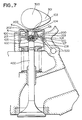
- a valve actuating mechanism has been composed to be light in weight for a cam to directly strike a shaft end of a valve, and such a mechanism has also been employed with the valve lash adjuster as shown in Fig. 7.
- the valve lash adjuster is composed of a bucket X and the oil pressure unit Y of the lash adjuster housed there in, and is placed between a cam 300 and the shaft end of a valve 400.
- the oil pressure unit Y is slidably mounted on the outer circumference of a plunger 101 shaped in cylinder form and having an oil hole 104 at its bottoms.
- the unit Y comprises a body 100 of cylinder shape defining a high pressure chamber 102 in relation with the bottom of the body 100; an elastic member 105 provided in the high pressure chamber 102 and biasing the body 100 downward; a check valve 106 disposed in the high pressure chamber for opening and closing the oil hole 104; and a valve spring 107 supporting the check valve 106 and a check valve cage 108 in the high pressure chamber 102.
- the oil pressure unit Y is housed in the bucket X, defining a main reservoir 103 as an oil storage between the rear side of a face disc 202 and the hollow portion of the plunger 101 as well as a sub-reservoir 200 communicating, via an overflow recess 203, with the main reservoir 103 partitioned with the circumferential wall of the plunger 101, the sub-reservoir 200 being supplied with the actuating oil through an oil feed hole 500 of a cylinder head and an oil hole 510 of the bucket X.
- the cam 300 contacts the face disc 202 of the bucket X, while the shaft end of the valve 400 contacts the closed face of the body 100, so that the cam 300 strikes the shaft end of the valve 400 via the valve lash adjuster.
- the valve lash adjuster makes use of the incompressibility of the actuating oil effected when exerting pressure to the actuating oil filled in the high pressure chamber 102, and a repulsion wherein the elastic member 105 expands in the chamber when releasing the pressure so as to rectify the space to be zero which has been thermally deformed in the valve actuating mechanism.
- a part of the oil to be supplied to the sub-reservoir 200 leaks via a space between the outer circumference of the oil pressure unit Y (the outer circumference of the body 100 in the drawing) and the sleeve 201 forming a partition of the sub-reservoir 200.
- the oil pressure unit Y is compressed as shown in Fig. 8, that is, it is most shortened or pressed to a maximum (bottomed condition). If the engine restarts under this condition, the sliding stroke between the plunger 101 and the body 100 is a maximum, and the oil is absorbed into the high pressure chamber 102. But if the oil leaks as said above when the engine stops, the oil is not supplied thereinto from a cylinder head, and accordingly not enough oil is supplied into the main reservoir 103 from the sub-reservoir 200.
- the present invention has been devised, and it is an object of the invention to provide a structure which can prevent the leakage of the oil from the reservoirs when the oil pressure unit is bottomed or pressed to a maximum while the engine is at rest.
- the sealing device serves to prevent the leakages from the main and sub-reservoirs.
- the oil amount within the main reservoir is kept sufficient thereby, and although the oil is not supplied from the cylinder head, the high pressure chamber is supplied with the actuating oil when restarting the engine, and air is not absorbed.
- Figs.1 to 3 of the drawings show one example of the invention.
- the reference numeral 1 is an oil pressure unit; 10 is a body composing the unit 1; 11 is a plunger also composing the unit 1; 12 is a high pressure chamber defined between the body 10 and the plunger 11; 13 is a main reservoir defined in the plunger 11; 14 is an oil hole communicating between the high pressure chamber 12 and the main reservoir 13; 2 is a bucket; 20 is a sub-reservoir defined by a wall portion 21 furnished within the bucket 2; 3 is a cam; 4 is a valve; and 5 is a valve spring.
- a recess 10a is formed at the lower end of the outer circumference of the body 10, in which an O-ring 60 is fitted which is a sealing device of this invention.
- the O-ring 60 contacts the side wall portion 21 of the sub-reservoir 20 and closes the space between the wall portion 21 and the outer circumference of the body 10 and checks the oil leakage from the sub-reservoir 20. Therefore, if the engine stops while a nose 30 of the cam 3 presses the face disc 22 of the bucket 2, that is, while the oil pressure unit 1 is bottomed or pressed to a maximum, a sufficient oil amount may be kept within the main reservoir 13, and air is prevented from going into the high pressure chamber 12 when re-starting the internal combustion engine.
- the actuating oil is supplied to the sub-reservoir 20 from the cylinder head through an oil field hole and no problem arises about the oil amounts of the reservoirs 13, 20.
- the actuating oil stored in the main reservoir 13 and the sub-reservoir 20 does not go to the cylinder head from the oil hole 510 of the bucket 2 (this is the same when the entire actuating valve mechanism is tilted reversely to Fig.2 and the oil hole faces downward).
- the wall portion 21 of the sub-reservoir 20 is formed in taper at the lower side thereof as shown in Fig.3, the O-ring 60 is checked from wearing while an exact sealing is possible.
- Fig.4 shows a modified ring 61 instead of the O-ring 60;
- Figs.5(a) to (e) show that sealing materials 62 to 66 are directly fixed to the lower side of the outer circumference of the body 10, or via back metals 70 to 72 or a patch 73;
- Fig. 6 shows that a sealing material 67 is attached to the lower end of the wall portion 21 of the sub-reservoir 20, while on the lower part of the body 10 a flange 68 is projecting.
- the modified ring 61 and the sealing materials 62 to 66 are used in the invention, and in Fig.6, the sealing material 67 and the projecting flange 68 both serve as a sealing device.
- valve lash adjuster is in general supplied with actuating oil mixed with air, and this air is purged from the clearance between the outer circumference of the body 10 and the wall portion 21 of the sub-reservoir 21, and in each of the above mentioned examples, the air purging effected is secured.
- the sealing device checks the oil leakage from the clearance between the outer circumference of the unit and the side wall portion of the sub-reservoir, so that the oil amount is kept full in the both reservoirs, and air is checked from entering the high pressure chamber.
Landscapes
- Engineering & Computer Science (AREA)
- Mechanical Engineering (AREA)
- General Engineering & Computer Science (AREA)
- Valve-Gear Or Valve Arrangements (AREA)
Applications Claiming Priority (2)
| Application Number | Priority Date | Filing Date | Title |
|---|---|---|---|
| JP139325/89 | 1989-06-02 | ||
| JP1139325A JP2782087B2 (ja) | 1989-06-02 | 1989-06-02 | 直動型油圧ラッシュアジャスタ |
Publications (2)
| Publication Number | Publication Date |
|---|---|
| EP0400602A1 EP0400602A1 (en) | 1990-12-05 |
| EP0400602B1 true EP0400602B1 (en) | 1993-04-14 |
Family
ID=15242684
Family Applications (1)
| Application Number | Title | Priority Date | Filing Date |
|---|---|---|---|
| EP90110259A Expired - Lifetime EP0400602B1 (en) | 1989-06-02 | 1990-05-30 | An oil pressure lash adjuster of a directly acting type |
Country Status (5)
| Country | Link |
|---|---|
| US (1) | US5029560A (ja) |
| EP (1) | EP0400602B1 (ja) |
| JP (1) | JP2782087B2 (ja) |
| KR (1) | KR940001315B1 (ja) |
| DE (1) | DE69001324T2 (ja) |
Families Citing this family (2)
| Publication number | Priority date | Publication date | Assignee | Title |
|---|---|---|---|---|
| DE4340035B4 (de) * | 1992-12-10 | 2006-02-23 | Ina-Schaeffler Kg | Mechanischer Tassenstößel |
| DE19503699A1 (de) * | 1995-02-04 | 1996-08-08 | Schaeffler Waelzlager Kg | Hydraulischer Ventiltriebsstößel |
Family Cites Families (13)
| Publication number | Priority date | Publication date | Assignee | Title |
|---|---|---|---|---|
| US4590898A (en) * | 1979-12-05 | 1986-05-27 | Eaton Corporation | Hydraulic tappet for direct-acting valve gear |
| DE3006644A1 (de) * | 1980-02-22 | 1981-09-03 | Motomak Motorenbau, Maschinen- u. Werkzeugfabrik, Konstruktionen GmbH, 8070 Ingolstadt | Ventilstoessel fuer brennkraftmaschinen mit obenliegender nockenwelle |
| US4392462A (en) * | 1980-12-22 | 1983-07-12 | Stanadyne, Inc. | Inverted bucket tappet with seal |
| US4715334A (en) * | 1983-12-07 | 1987-12-29 | Eaton Corporation | Self contained hydraulic bucket lifter |
| DE3412175A1 (de) * | 1984-03-31 | 1985-10-10 | Motomak Motorenbau, Maschinen- u. Werkzeugfabrik, Konstruktionen GmbH, 8070 Ingolstadt | Tassenfoermiges gehaeuse eines sich selbsttaetig hydraulisch einstellenden ventilstoessels fuer brennkraftmaschinen mit obenliegender nockenwelle |
| DE3500425A1 (de) * | 1985-01-09 | 1986-07-10 | Motomak Motorenbau, Maschinen- u. Werkzeugfabrik, Konstruktionen GmbH, 8070 Ingolstadt | Hydraulischer tassenstoessel fuer verbrennungsmotoren |
| DE3513161A1 (de) * | 1985-04-12 | 1986-10-16 | Goetze Ag, 5093 Burscheid | Ventilspielausgleichseinrichtung |
| US4694790A (en) * | 1985-05-03 | 1987-09-22 | Stanadyne, Inc. | Inverted bucket tappet with collapsing diaphragm seal |
| DE3615791A1 (de) * | 1985-05-22 | 1986-11-27 | Volkswagen AG, 3180 Wolfsburg | Abgeschlossene hydraulische laengenausgleichsvorrichtung, insbesondere fuer ventile von brennkraftmaschinen |
| DE3528432A1 (de) * | 1985-08-08 | 1987-02-19 | Motomak | Sich selbsttaetig hydraulisch einstellender ventilstoessel |
| JPS62101013U (ja) * | 1985-12-17 | 1987-06-27 | ||
| DE3639911A1 (de) * | 1986-11-22 | 1988-06-01 | Schaeffler Waelzlager Kg | Sich selbsttaetig hydraulisch einstellender ventilstoessel |
| DE3812333A1 (de) * | 1988-04-14 | 1989-10-26 | Schaeffler Waelzlager Kg | Sich selbsttaetig hydraulisch einstellender ventilstoessel |
-
1989
- 1989-06-02 JP JP1139325A patent/JP2782087B2/ja not_active Expired - Lifetime
-
1990
- 1990-05-30 EP EP90110259A patent/EP0400602B1/en not_active Expired - Lifetime
- 1990-05-30 DE DE90110259T patent/DE69001324T2/de not_active Expired - Lifetime
- 1990-05-31 US US07/531,030 patent/US5029560A/en not_active Expired - Lifetime
- 1990-06-02 KR KR1019900008161A patent/KR940001315B1/ko not_active IP Right Cessation
Also Published As
| Publication number | Publication date |
|---|---|
| DE69001324T2 (de) | 1993-10-28 |
| JP2782087B2 (ja) | 1998-07-30 |
| US5029560A (en) | 1991-07-09 |
| DE69001324D1 (de) | 1993-05-19 |
| KR910001214A (ko) | 1991-01-30 |
| JPH039006A (ja) | 1991-01-16 |
| KR940001315B1 (ko) | 1994-02-19 |
| EP0400602A1 (en) | 1990-12-05 |
Similar Documents
| Publication | Publication Date | Title |
|---|---|---|
| US4941438A (en) | Hydraulic valve-lash adjuster | |
| US3521608A (en) | Self-contained hydraulic valve lifter | |
| US4590898A (en) | Hydraulic tappet for direct-acting valve gear | |
| US5310385A (en) | Oil-operated tensioner with oil-sealed air entrance | |
| US4462364A (en) | Hydraulic lash adjuster | |
| GB2108620A (en) | Hydraulic lifter | |
| EP0746673B1 (en) | Rotary valve with sealing means | |
| US4470381A (en) | Hydraulic tappet for direct-acting valve gear | |
| US5311845A (en) | Oil pressure lash adjuster equipped with air vent | |
| US4887566A (en) | Hydraulic valve lash adjuster | |
| EP0400602B1 (en) | An oil pressure lash adjuster of a directly acting type | |
| US4635593A (en) | Hydraulic valve lifter | |
| EP0400601B1 (en) | An oil pressure rush adjuster of a directly acting type | |
| US4554895A (en) | Hydraulic lifter for internal combustion engines | |
| US4662325A (en) | Self-contained hydraulic valve lifter | |
| US5595149A (en) | Method of first filling of a hydraulic valve actuating device | |
| JP3288744B2 (ja) | 内燃機関用油圧ラッシュアジャスタ | |
| US2871839A (en) | Self-contained hydraulic lash adjuster | |
| JPH05195724A (ja) | 内燃機関用液圧弁すき間補償装置 | |
| JPS60206915A (ja) | 弁間隙自動補正装置 | |
| JPS6039441Y2 (ja) | 密封型油圧リフタ | |
| JPS6032003B2 (ja) | Ohc用スタツド式密封型ラツシユアジヤスタ | |
| JP3288753B2 (ja) | 直動型油圧ラッシュアジャスタ | |
| JPS647201Y2 (ja) | ||
| JPH0728248U (ja) | ショックアブソーバ |
Legal Events
| Date | Code | Title | Description |
|---|---|---|---|
| PUAI | Public reference made under article 153(3) epc to a published international application that has entered the european phase |
Free format text: ORIGINAL CODE: 0009012 |
|
| AK | Designated contracting states |
Kind code of ref document: A1 Designated state(s): DE FR GB |
|
| 17P | Request for examination filed |
Effective date: 19901220 |
|
| 17Q | First examination report despatched |
Effective date: 19910529 |
|
| GRAA | (expected) grant |
Free format text: ORIGINAL CODE: 0009210 |
|
| AK | Designated contracting states |
Kind code of ref document: B1 Designated state(s): DE FR GB |
|
| REF | Corresponds to: |
Ref document number: 69001324 Country of ref document: DE Date of ref document: 19930519 |
|
| ET | Fr: translation filed | ||
| PLBE | No opposition filed within time limit |
Free format text: ORIGINAL CODE: 0009261 |
|
| STAA | Information on the status of an ep patent application or granted ep patent |
Free format text: STATUS: NO OPPOSITION FILED WITHIN TIME LIMIT |
|
| 26N | No opposition filed | ||
| REG | Reference to a national code |
Ref country code: GB Ref legal event code: IF02 |
|
| PGFP | Annual fee paid to national office [announced via postgrant information from national office to epo] |
Ref country code: FR Payment date: 20090519 Year of fee payment: 20 Ref country code: DE Payment date: 20090526 Year of fee payment: 20 |
|
| PGFP | Annual fee paid to national office [announced via postgrant information from national office to epo] |
Ref country code: GB Payment date: 20090521 Year of fee payment: 20 |
|
| PG25 | Lapsed in a contracting state [announced via postgrant information from national office to epo] |
Ref country code: GB Free format text: LAPSE BECAUSE OF EXPIRATION OF PROTECTION Effective date: 20100529 |
|
| PG25 | Lapsed in a contracting state [announced via postgrant information from national office to epo] |
Ref country code: DE Free format text: LAPSE BECAUSE OF EXPIRATION OF PROTECTION Effective date: 20100530 |