EP0400401A2 - Vorrichtung zum Regeln eines Volumenstroms in einem Führungsrohr - Google Patents
Vorrichtung zum Regeln eines Volumenstroms in einem Führungsrohr Download PDFInfo
- Publication number
- EP0400401A2 EP0400401A2 EP19900109297 EP90109297A EP0400401A2 EP 0400401 A2 EP0400401 A2 EP 0400401A2 EP 19900109297 EP19900109297 EP 19900109297 EP 90109297 A EP90109297 A EP 90109297A EP 0400401 A2 EP0400401 A2 EP 0400401A2
- Authority
- EP
- European Patent Office
- Prior art keywords
- adjusting
- controller
- flap
- guide tube
- gear
- Prior art date
- Legal status (The legal status is an assumption and is not a legal conclusion. Google has not performed a legal analysis and makes no representation as to the accuracy of the status listed.)
- Granted
Links
- 238000009423 ventilation Methods 0.000 claims abstract description 7
- 238000004378 air conditioning Methods 0.000 claims abstract description 5
- 230000001105 regulatory effect Effects 0.000 claims description 7
- 239000006096 absorbing agent Substances 0.000 claims description 4
- 230000035939 shock Effects 0.000 claims description 4
- 238000011109 contamination Methods 0.000 description 1
- 230000008878 coupling Effects 0.000 description 1
- 238000010168 coupling process Methods 0.000 description 1
- 238000005859 coupling reaction Methods 0.000 description 1
- 230000000694 effects Effects 0.000 description 1
- 238000012423 maintenance Methods 0.000 description 1
- 239000000523 sample Substances 0.000 description 1
- 230000036642 wellbeing Effects 0.000 description 1
Images
Classifications
-
- G—PHYSICS
- G05—CONTROLLING; REGULATING
- G05D—SYSTEMS FOR CONTROLLING OR REGULATING NON-ELECTRIC VARIABLES
- G05D23/00—Control of temperature
- G05D23/19—Control of temperature characterised by the use of electric means
- G05D23/1919—Control of temperature characterised by the use of electric means characterised by the type of controller
-
- F—MECHANICAL ENGINEERING; LIGHTING; HEATING; WEAPONS; BLASTING
- F24—HEATING; RANGES; VENTILATING
- F24F—AIR-CONDITIONING; AIR-HUMIDIFICATION; VENTILATION; USE OF AIR CURRENTS FOR SCREENING
- F24F11/00—Control or safety arrangements
- F24F11/70—Control systems characterised by their outputs; Constructional details thereof
- F24F11/72—Control systems characterised by their outputs; Constructional details thereof for controlling the supply of treated air, e.g. its pressure
- F24F11/74—Control systems characterised by their outputs; Constructional details thereof for controlling the supply of treated air, e.g. its pressure for controlling air flow rate or air velocity
-
- Y—GENERAL TAGGING OF NEW TECHNOLOGICAL DEVELOPMENTS; GENERAL TAGGING OF CROSS-SECTIONAL TECHNOLOGIES SPANNING OVER SEVERAL SECTIONS OF THE IPC; TECHNICAL SUBJECTS COVERED BY FORMER USPC CROSS-REFERENCE ART COLLECTIONS [XRACs] AND DIGESTS
- Y10—TECHNICAL SUBJECTS COVERED BY FORMER USPC
- Y10T—TECHNICAL SUBJECTS COVERED BY FORMER US CLASSIFICATION
- Y10T137/00—Fluid handling
- Y10T137/8158—With indicator, register, recorder, alarm or inspection means
- Y10T137/8225—Position or extent of motion indicator
Definitions
- the invention relates to a device for regulating a volume flow in a guide tube, in particular for regulating the air flow in a ventilation system or an air conditioning system, an adjusting flap being arranged in the guide tube, in particular being rotatable, in particular rotatable about an axis of rotation.
- An essential task of ventilation systems is the introduction of fresh, cleaned air into, for example, work and common rooms as well as the removal of used and polluted air. Depending on the desired requirements, these systems can also heat, cool, humidify and dehumidify.
- a volume flow controller is shown, for example, in German Patent 33 36 911.
- a corresponding adjustment flap is controlled by a device for measuring the flow of the air, with manifolds with flow openings arranged in the flow cross section of the gas guide pipe being provided, into which the air flows.
- all flow intake openings are directed towards the flow, the flow being directed to collecting pipes which are connected to a tubular collecting housing. Its axis extends parallel to the axis of the gas pipe.
- a corresponding measuring probe is also assigned to it.
- This device has proven itself in practice, but the control of the adjustment flap is carried out via the relatively complicated measuring system.
- the inventor has set himself the task of developing a device of the type mentioned above, by means of which a substantially more direct control of the adjusting flap is possible, which also works simply and without complications or wear.
- an adjusting device for the adjusting flap and the adjusting device a controller are assigned to the guide tube, the latter being controllable by a control unit, in particular a room thermostat.
- the adjusting device and the regulator are preferably located outside the guide tube, so that they are not influenced by the volume flow flowing through the guide tube. This also does not result in contamination or the like of the control unit.
- the control takes place exclusively via the room thermostat, so that direct control of the controller appears possible here.
- the room thermostat then sends appropriate switching signals to the controller if the room temperature is too low or too high.
- the adjusting flap is then correspondingly closed or opened via the adjusting device. This is very simple and in practice has no complications. Maintenance is rarely necessary.
- the setting device should preferably be coupled to the controller via gear elements. Both the adjusting device and the controller sit together on the guide tube, so that a compact unit is formed.
- a gear wheel or the like can be seated on the axis of rotation of the adjusting flap, which is attacked directly by a toothed strip which is assigned to the adjusting device in a linearly displaceable manner.
- gear elements are also possible, such as a chain connected to the linearly movable toothed strip via corresponding deflection rollers. There should be no limit to the inventive idea here.
- a shock absorber should be assigned to the gear elements, via which the volume flow controller can be precisely adjusted, a very high control accuracy then being achieved.
- a toothed rack is provided as the gear element, then a toothed circular disk, a gearwheel or the like should be connected to the shaft of a drive assigned to the controller, the toothing of which engages a toothing of this toothed rack and thus causes the linear movement of the toothed rack.
- a toothed rack is provided as the gear element, then a toothed circular disk, a gearwheel or the like should be connected to the shaft of a drive assigned to the controller, the toothing of which engages a toothing of this toothed rack and thus causes the linear movement of the toothed rack.
- other couplings are also conceivable here.
- An electric motor which can be switched from 1 to 10 volts is preferably used as the drive.
- a volume flow controller 2 is seated on a pipe section 1 of a ventilation or air-conditioning system, not shown.
- This volume flow controller 2 essentially consists of an actual setting device 3 and a controller 4.
- An adjusting flap 5, shown in broken lines in FIG. 2, is operated via the adjusting device 3, which can be round or oval, in particular, depending on the cross section of the pipe section 1.
- This adjusting flap 5 rotates about an axis of rotation 6 and is connected to the controller 4 via corresponding gear elements.
- a gear 7 can be placed on the axis of rotation 6, which is also only indicated by dashed lines in the present exemplary embodiment.
- the gear 7 has an external toothing, which is combed by corresponding teeth of a rack 8.
- the position of the adjusting flap 5 can be regulated by rotating the gear wheel 7 via the axis of rotation 6.
- gear elements are also conceivable here, for example a corresponding connecting chain, only one chain link 9 being indicated here, which then connects the toothed strip 8 to the gear wheel 7 or to another gear part for rotating the axis of rotation 6 via corresponding deflection rollers.
- the gear element also includes a shock absorber, not shown, by means of which the activity of the gear elements can be precisely regulated.
- a scale 10 is provided above the rack 8, on which the position of the adjusting flap 5 can be read.
- the toothed rack 8 also has a further set of teeth 11, which is attacked by a semicircular toothed disk 12.
- This semicircular toothed disk is connected via a further axis of rotation 13 to a servomotor provided in the controller 4, the controller 4 itself being flanged to the adjusting device 3 and the entire volume flow controller 2 being connected to the pipe section 1 via a semicircular connecting plate 14.
- another connecting element to the toothed rack such as a toothed wheel or a toothed rack, can also be provided.
- a toothed wheel or a toothed rack can also be provided.
- the motor is preferably an electric motor which can be switched from 1 to 10 volts.
- the gear units within the adjustment device are very precisely matched to this engine, whereby the regulator can be precisely adjusted by the attached shock absorber and the control accuracy is very high (difference less than 5%).
- this volume flow controller is, in particular, that neither a measuring cross nor an additional control unit is needed. All that is required is an adjustment flap, either round or oval, and a standard servomotor (electric or pneumatic) that can be regulated from 0 to 10 volts.
- the controller is controlled directly from the room thermostat, and the room thermostat emits appropriate signals if the room temperature is too low or too high. This drives the servomotor, which closes or opens the adjusting flap via the gear parts of the adjusting device.
Landscapes
- Engineering & Computer Science (AREA)
- Physics & Mathematics (AREA)
- General Engineering & Computer Science (AREA)
- Automation & Control Theory (AREA)
- Fluid Mechanics (AREA)
- Chemical & Material Sciences (AREA)
- Combustion & Propulsion (AREA)
- Mechanical Engineering (AREA)
- General Physics & Mathematics (AREA)
- Air-Flow Control Members (AREA)
- Duct Arrangements (AREA)
- Air Conditioning Control Device (AREA)
- Regulation And Control Of Combustion (AREA)
- Electrical Discharge Machining, Electrochemical Machining, And Combined Machining (AREA)
- External Artificial Organs (AREA)
- Electrically Driven Valve-Operating Means (AREA)
- Temperature-Responsive Valves (AREA)
- Fluid-Driven Valves (AREA)
Abstract
Description
- Die Erfindung betrifft eine Vorrichtung zum Regeln eines Volumenstroms in einem Führungsrohr, insbesondere zum Regeln des Luftstromes in einem Lüftungssystem bzw. einer Klimaanlage, wobei eine Einstellklappe veränderbar, insbesondere um eine Drehachse drehbar, in dem Führungsrohr angeordnet ist.
- Wesentliche Aufgabe von Lüftungssystemen ist das Einbringen frischer, gereinigter Luft in beispielsweise Arbeits- und Aufenthaltsräume sowie das Abführen verbrauchter und schadstoffhaltiger Luft. Je nach gewünschtem Bedarf können diese Anlagen zusätzlich heizen, kühlen, be- und entfeuchten.
- Da das Wohlbefinden des Menschen erheblich von diesen Lüftungssystemen bzw. Klimaanlagen abhängt, ist deren Regelung von erheblicher Bedeutung. Ein derartiger Volumenstromregler ist beispielsweise in der Deutschen Patentschrift 33 36 911 aufgezeigt. Dort wird eine entsprechende Einstellklappe von einer Vorrichtung zum Messen der Strömung der Luft gesteuert, wobei über den Strömungsquerschnitt des Gasführungsrohres verteilt angeordnete Sammelrohre mit Strömungsöffnungen vorgesehen sind, in die die Luft einströmt. Dabei sind sämtliche Strömungsaufnahmeöffnungen der Strömung entgegengerichtet, wobei die Strömung zu Sammelrohren geleitet wird, die mit einem rohrförmigen Sammelgehäuse verbunden sind. Dessen Achse erstreckt sich parallel zur Achse des Gasführungsrohres. Ferner ist ihm eine entsprechende Meßsonde zugeordnet. Diese Vorrichtung hat sich in der Praxis sehr bewährt, wobei aber die Steuerung der Einstellklappe über das relativ komplizierte Meßsystem erfolgt.
- Der Erfinder hat sich zur Aufgabe gestellt, eine Vorrichtung der oben genannten Art zu entwickeln, mittels welcher eine wesentlich direktere Ansteuerung der Einstellklappe möglich ist, welche zudem einfach und ohne Komplikationen bzw. Verschleiß arbeitet.
- Zur Lösung dieser Aufgabe führt, daß dem Führungsrohr eine Einstellvorrichtung für die Einstellklappe und der Einstellvorrichtung ein Regler zugeordnet ist, welch letzterer von einer Regeleinheit, insbesondere einem Raumthermostat steuerbar ist.
- Bevorzugt befinden sich Einstellvorrichtung und Regler außerhalb des Führungsrohres, so daß sie von dem das Führungsrohr durchfließenden Volumenstrom nicht beeinflußt werden. Hierdurch kommt es auch nicht zu Verschmutzungen od. dgl. der Regeleinheit.
- Die Steuerung erfolgt ausschließlich über den Raumthermostat, so daß hier eine direkte Ansteuerung des Reglers möglich erscheint. Der Raumthermostat gibt dann entsprechende Schaltsignale an den Regler ab, wenn die Raumtemperatur zu niedrig oder zu hoch ist. Damit wird dann die Einstellklappe über die Einstellvorrichtung entsprechend geschlossen bzw. geöffnet. Dies ist sehr einfach und bietet in der Praxis keinerlei Komplikationen. Eine Wartung ist nur in den seltensten Fällen notwendig.
- Bevorzugt soll die Einstellvorrichtung über Getriebeelemente mit dem Regler gekoppelt sein. Dabei sitzt sowohl die Einstellvorrichtung wie auch der Regler gemeinsam dem Führungsrohr auf, so daß eine kompakte Einheit gebildet ist.
- In einer Ausführungsform der Erfindung kann der Drehachse der Einstellklappe ein Zahnrad od. dgl. aufsitzen, welches direkt von einer Zahnleiste angegriffen wird, die linear verschiebbar der Einstellvorrichtung zugeordnet ist. Es sind jedoch auch andere Getriebeelemente, wie beispielsweise eine mit der linear bewegbaren Zahnleiste verbundene Kette über entsprechende Umlenkrollen möglich. Hier soll dem erfinderischen Gedanken keine Grenze gesetzt sein.
- Bevorzugt soll den Getriebeelementen jedoch ein Stoßdämpfer zugeordnet sein, über welchen sich der Volumenstromregler exakt einjustieren läßt, wobei dann eine sehr hohe Regelgenauigkeit erreicht wird.
- Ist als Getriebeelement eine Zahnleiste vorgesehen, so soll mit der Welle eines dem Regler zugeordneten Antriebes eine Zahnhalbrundscheibe, ein Zahnrad od. dgl. verbunden sein, wobei dessen Zahnung eine Zahnung dieser Zahnleiste angreift und so die lineare Bewegung der Zahnleiste verursacht. Auch hier sind jedoch andere Kopplungen denkbar.
- Als Antrieb wird bevorzugt ein Elektromotor benutzt, welcher von 1 bis 10 Volt schaltbar ist.
- Weitere Vorteile, Merkmale und Einzelheiten der Erfindung ergeben sich aus der nachfolgenden Beschreibung eines bevorzugten Ausführungsbeispiels sowie anhand der Zeichnung; diese zeigt in
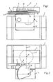
- Fig. 1 eine Seitenansicht eines erfindungsgemäßen Volumenstromreglers, montiert auf einen Rohrabschnitt eines entsprechenden Lüftungssystems;
- Fig. 2 eine Draufsicht auf den Volumenstromregler gemäß Figur 1.
- Gemäß Figur 1 sitzt einem Rohrabschnitt 1 eines nicht näher dargestellten Lüftungs- bzw. Klimasystems ein Volumenstromregler 2 auf. Dieser Volumenstromregler 2 besteht im wesentlichen aus einer eigentlichen Einstellvorrichtung 3 und einem Regler 4.
- Über die Einstellvorrichtung 3 wird eine in Figur 2 gestrichelt dargestellte Einstellklappe 5 bedient, welche insbesondere je nach dem Querschnitt des Rohrabschnitts 1 rund oder oval sein kann. Dabei dreht diese Einstellklappe 5 um eine Drehachse 6 und ist über entsprechende Getriebeelemente mit dem Regler 4 verbunden. Beispielsweise kann der Drehachse 6 ein Zahnrad 7 aufgesetzt sein, welches im vorliegenden Ausführungsbeispiel ebenfalls nur gestrichelt angedeutet ist. Das Zahnrad 7 besitzt dabei eine Außenzahnung, die von entsprechenden Zähnen einer Zahnleiste 8 gekämmt wird.
- Wird diese Zahnleiste 8 in Richtung x verschoben, so kann durch Drehung des Zahnrades 7 über die Drehachse 6 die Stellung der Einstellklappe 5 reguliert werden.
- Jedoch sind hier auch andere Getriebeelemente denkbar, wie beispielsweise eine entsprechende Verbindungskette, wobei hier nur ein Kettenglied 9 angedeutet ist, welches die Zahnleiste 8 dann über entsprechende Umlenkrollen entweder mit dem Zahnrad 7 oder mit einem anderen Getriebeteil zum Drehen der Drehachse 6 verbindet.
- Erfindungsgemäß gehört zu dem Getriebeelement auch ein nicht näher dargestellter Stoßdämpfer, über den sich die Tätigkeit der Getriebeelemente exakt regulieren läßt.
- Oberhalb der Zahnleiste 8 ist im übrigen eine Skalierung 10 vorgesehen, auf der die Stellung der Einstellklappe 5 abgelesen werden kann.
- Die Zahnleiste 8 besitzt ferner eine weitere Zahnung 11, welche von einer Zahnhalbrundscheibe 12 angegriffen wird. Diese Zahnhalbrundscheibe steht über eine weitere Drehachse 13 mit einem im Regler 4 vorgesehenen Stellmotor in Verbindung, wobei der Regler 4 selbst an der Einstellvorrichtung 3 angeflanscht ist und der gesamte Volumenstromregler 2 über eine Halbrundverbindungslasche 14 mit dem Rohrabschnitt 1 verbunden ist.
- Anstelle der Zahnhalbrundscheibe 12 kann auch ein anderes Verbindungselement zur Zahnleiste, wie beispielsweise ein Zahnrad oder eine Zahnstange vorgesehen sein. Anbieten würden sich auch zwei gegeneinander arbeitende Zahnleisten.
- Bei dem Motor handelt es sich bevorzugt um einen Elektromotor, welcher von 1 bis 10 Volt geschaltet werden kann. Die Getriebeeinrichtungen innerhalb der Einstellvorrichtung sind sehr exakt auf diesen Motor abgestimmt, wobei sich durch den angebrachten Stoßdämpfer der Regler exakt einjustieren läßt und die Regelgenauigkeit sehr hoch ist (Differenz unter 5%).
- Der Vorteil dieses Volumenstromreglers liegt insbesondere darin, daß weder ein Meßkreuz noch eine zusätzliche Regeleinheit gebraucht wird. Erforderlich ist lediglich eine Einstellklappe, entweder rund oder oval, und ein handelsüblicher Stellmotor (elektrisch oder pneumatisch), welcher von 0 bis 10 Volt reguliert werden kann. Die Steuerung des Reglers erfolgt direkt vom Raumthermostat aus, wobei der Raumthermostat entsprechende Signale abgibt, wenn die Raumtemperatur zu niedrig oder zu hoch ist. Hierdurch wird der Stellmotor angetrieben, der über die Getriebeteile der Einstellvorrichtung die Einstellklappe schließt oder öffnet.
- Der Volumenstromregler ist auch sehr wartungsfreundlich, da keine Verschmutzungen eines Meßkreuzes oder einer Regeleinheit möglich sind. POSITIONSZAHLENLISTE
- 1 Rohrabschnitt
- 2 Volumenstromregler
- 3 Einstellvorrichtung
- 4 Regler
- 5 Einstellklappe
- 6 Drehachse
- 7 Zahnrad
- 8 Zahnleiste
- 9 Kettenglied
- 10 Skalierung
- 11 Zahnung
- 12 Zahnhalbrundscheibe
- 13 Drehachse
- 14 Verbindungslasche
- 15
- 16
- 17
- 18
- 19
- 20
- 21
- 22
- 23
- 24
- 25
- 26
- 27
- 28
- 29
- 30
- 31
- 32
- 33
- 34
- 35
- 36
- 37
- 38
- 39
- 40
- 41
- 42
- 43
- 44
- 45
- 46
- 47
- 48
- 49
- 50
- 51
- 52
- 53
- 54
- 55
- 56
- 57
- 58
- 59
- 60
- 61
- 62
- 63
- 64
- 65
- 66
- x Bewegung von 8
Claims (7)
dadurch gekennzeichnet,
daß dem Führungsrohr (1) eine Einstellvorrichtung (3) für die Einstellklappe (5) und der Einstellvorrichtung ein Regler (4) zugeordnet ist, welch letzterer von einer Regeleinheit, insbesondere einem Raumthermostat, steuerbar ist.
Applications Claiming Priority (2)
| Application Number | Priority Date | Filing Date | Title |
|---|---|---|---|
| DE3917360 | 1989-05-29 | ||
| DE19893917360 DE3917360A1 (de) | 1989-05-29 | 1989-05-29 | Vorrichtung zum regeln eines volumenstroms in einem fuehrungsrohr |
Publications (3)
| Publication Number | Publication Date |
|---|---|
| EP0400401A2 true EP0400401A2 (de) | 1990-12-05 |
| EP0400401A3 EP0400401A3 (de) | 1992-03-18 |
| EP0400401B1 EP0400401B1 (de) | 1996-11-06 |
Family
ID=6381558
Family Applications (1)
| Application Number | Title | Priority Date | Filing Date |
|---|---|---|---|
| EP19900109297 Expired - Lifetime EP0400401B1 (de) | 1989-05-29 | 1990-05-17 | Vorrichtung zum Regeln eines Volumenstroms in einem Führungsrohr |
Country Status (9)
| Country | Link |
|---|---|
| US (1) | US5050638A (de) |
| EP (1) | EP0400401B1 (de) |
| JP (1) | JPH03274349A (de) |
| AT (1) | ATE145071T1 (de) |
| CA (1) | CA2017623A1 (de) |
| DD (1) | DD294770A5 (de) |
| DE (2) | DE3917360A1 (de) |
| ES (1) | ES2093619T3 (de) |
| PT (1) | PT92332B (de) |
Cited By (2)
| Publication number | Priority date | Publication date | Assignee | Title |
|---|---|---|---|---|
| EP1947400A2 (de) | 2007-01-17 | 2008-07-23 | Schako Klima Luft Ferdinand Schad KG | Verfahren und Vorrichtung zum Be- und/oder Entlüften eines Raumes |
| CN107014053A (zh) * | 2017-04-28 | 2017-08-04 | 珠海格力电器股份有限公司 | 一种空调及其导风板运动机构 |
Families Citing this family (11)
| Publication number | Priority date | Publication date | Assignee | Title |
|---|---|---|---|---|
| DE4135758A1 (de) * | 1991-10-30 | 1993-08-12 | Schako Metallwarenfabrik | Volumenstromregler |
| DE9303288U1 (de) * | 1993-03-06 | 1993-05-27 | "Schako" Metallwarenfabrik Ferdinand Schad KG, 7201 Kolbingen | Luftführungssystem |
| US5325888A (en) * | 1993-04-30 | 1994-07-05 | Stary Gary M | Pipeline valve transmission apparatus |
| US5674125A (en) * | 1995-01-24 | 1997-10-07 | American Standard Inc. | Fresh air flow modulation device |
| US5647399A (en) * | 1995-08-03 | 1997-07-15 | Valeo Climate Control Inc. | Flow control device |
| DE102007006418B3 (de) * | 2007-01-17 | 2008-11-27 | Schako Klima Luft Ferdinand Schad Kg Zweigniederlassung Kolbingen | Verfahren und Vorrichtung zum Be- oder Entlüften eines relativ lufdichten Raumes |
| US8191860B2 (en) * | 2008-07-31 | 2012-06-05 | Honeywell International Inc. | Low profile valve actuator having high torque output |
| CN102094983B (zh) * | 2011-02-28 | 2012-12-19 | 浙江金卡高科技股份有限公司 | 翻板式燃气电机阀 |
| JP5104971B2 (ja) * | 2011-03-31 | 2012-12-19 | ダイキン工業株式会社 | 調湿換気装置 |
| DE102011053269A1 (de) | 2011-09-05 | 2013-03-07 | Schako Klima Luft, Ferdinand Schad Kg | Vorrichtung zum Regeln eines Luftvolumenstroms |
| US9115417B2 (en) | 2012-04-05 | 2015-08-25 | United Technologies Corporation | Liquid drop peening method and apparatus therefor |
Citations (6)
| Publication number | Priority date | Publication date | Assignee | Title |
|---|---|---|---|---|
| US1724990A (en) * | 1924-11-24 | 1929-08-20 | Bovey Thomas | Lever control for automobile heaters |
| US4291832A (en) * | 1979-05-07 | 1981-09-29 | Universal Pneumatic Controls, Inc. | System powered reset velocity controller |
| US4449664A (en) * | 1980-06-27 | 1984-05-22 | Topre Corporation | Air quantity regulating apparatus for air conditioning |
| EP0122466A2 (de) * | 1983-03-17 | 1984-10-24 | Emil Siegwart | Vorrichtung zum Steuern der Regelgrösse eines Strömungsmengenreglers einer Klimaanlage |
| US4545363A (en) * | 1984-07-05 | 1985-10-08 | Safe-Air Inc. | Ventilation damper control system |
| US4553695A (en) * | 1984-01-04 | 1985-11-19 | Grant Willie T | Automatic damper means for air ducts |
Family Cites Families (7)
| Publication number | Priority date | Publication date | Assignee | Title |
|---|---|---|---|---|
| US2393482A (en) * | 1946-01-22 | Damper | ||
| US842961A (en) * | 1906-05-18 | 1907-02-05 | Thomas F Kewley | Valve-operating mechanism for shower-bath apparatus. |
| US2912870A (en) * | 1957-12-16 | 1959-11-17 | Roberts Brass Mfg Co | Valve operating mechanism |
| US4327894A (en) * | 1980-05-21 | 1982-05-04 | Mks Instruments, Inc. | Linearized controlled valves |
| US4401260A (en) * | 1981-12-09 | 1983-08-30 | Grant Willie T | Self-operated air register damper |
| US4556169A (en) * | 1984-06-07 | 1985-12-03 | Honeywell Inc. | On-off thermostat based modulating air flow controller |
| GB8723763D0 (en) * | 1987-10-09 | 1987-11-11 | Hydro Tech Ltd | Liquid flow control device |
-
1989
- 1989-05-29 DE DE19893917360 patent/DE3917360A1/de not_active Withdrawn
- 1989-11-16 PT PT92332A patent/PT92332B/pt not_active IP Right Cessation
-
1990
- 1990-05-17 ES ES90109297T patent/ES2093619T3/es not_active Expired - Lifetime
- 1990-05-17 AT AT90109297T patent/ATE145071T1/de not_active IP Right Cessation
- 1990-05-17 EP EP19900109297 patent/EP0400401B1/de not_active Expired - Lifetime
- 1990-05-17 DE DE59010555T patent/DE59010555D1/de not_active Expired - Fee Related
- 1990-05-21 JP JP2129350A patent/JPH03274349A/ja active Pending
- 1990-05-25 DD DD90340996A patent/DD294770A5/de not_active IP Right Cessation
- 1990-05-28 CA CA 2017623 patent/CA2017623A1/en not_active Abandoned
- 1990-05-29 US US07/529,960 patent/US5050638A/en not_active Expired - Fee Related
Patent Citations (6)
| Publication number | Priority date | Publication date | Assignee | Title |
|---|---|---|---|---|
| US1724990A (en) * | 1924-11-24 | 1929-08-20 | Bovey Thomas | Lever control for automobile heaters |
| US4291832A (en) * | 1979-05-07 | 1981-09-29 | Universal Pneumatic Controls, Inc. | System powered reset velocity controller |
| US4449664A (en) * | 1980-06-27 | 1984-05-22 | Topre Corporation | Air quantity regulating apparatus for air conditioning |
| EP0122466A2 (de) * | 1983-03-17 | 1984-10-24 | Emil Siegwart | Vorrichtung zum Steuern der Regelgrösse eines Strömungsmengenreglers einer Klimaanlage |
| US4553695A (en) * | 1984-01-04 | 1985-11-19 | Grant Willie T | Automatic damper means for air ducts |
| US4545363A (en) * | 1984-07-05 | 1985-10-08 | Safe-Air Inc. | Ventilation damper control system |
Cited By (3)
| Publication number | Priority date | Publication date | Assignee | Title |
|---|---|---|---|---|
| EP1947400A2 (de) | 2007-01-17 | 2008-07-23 | Schako Klima Luft Ferdinand Schad KG | Verfahren und Vorrichtung zum Be- und/oder Entlüften eines Raumes |
| CN107014053A (zh) * | 2017-04-28 | 2017-08-04 | 珠海格力电器股份有限公司 | 一种空调及其导风板运动机构 |
| CN107014053B (zh) * | 2017-04-28 | 2020-11-13 | 珠海格力电器股份有限公司 | 一种空调及其导风板运动机构 |
Also Published As
| Publication number | Publication date |
|---|---|
| PT92332B (pt) | 1998-05-29 |
| JPH03274349A (ja) | 1991-12-05 |
| US5050638A (en) | 1991-09-24 |
| ATE145071T1 (de) | 1996-11-15 |
| ES2093619T3 (es) | 1997-01-01 |
| DE3917360A1 (de) | 1990-12-06 |
| DD294770A5 (de) | 1991-10-10 |
| PT92332A (pt) | 1991-01-08 |
| CA2017623A1 (en) | 1990-11-29 |
| DE59010555D1 (de) | 1996-12-12 |
| EP0400401B1 (de) | 1996-11-06 |
| EP0400401A3 (de) | 1992-03-18 |
Similar Documents
| Publication | Publication Date | Title |
|---|---|---|
| EP0400401B1 (de) | Vorrichtung zum Regeln eines Volumenstroms in einem Führungsrohr | |
| EP1904794B1 (de) | Stellantrieb | |
| DE69905465T2 (de) | Wärmetauscher | |
| EP0282758B1 (de) | Ventilanordnung | |
| DE1428043B2 (de) | Einrichtung zur Regelung eines Turboverdichters | |
| DE2542160C2 (de) | ||
| DE905682C (de) | Nachgiebige Rueckfuehrung fuer Regler mit Auslassdrossel | |
| DE4237009C2 (de) | Gasmengeneinstellsystem | |
| DE3204613A1 (de) | Gitterfoermige zuluftauslassvorrichtung fuer die belueftung oder beheizung eines raumes | |
| EP0848311B1 (de) | Verstelleinrichtung | |
| DE8906566U1 (de) | Vorrichtung zum Regeln eines Volumenstroms in einem Führungsrohr | |
| DE2219380C3 (de) | Volumenstromregler | |
| DE2441573C3 (de) | Verfahren, Anordnung und Vorrichtung zum Herstellen eines Reizklimas in Aufenthaltsraumen | |
| DE616042C (de) | Fluessigkeitsgetriebe | |
| DE2542964A1 (de) | Verfahren und vorrichtung zur regelung des volumenstromes in gasdurchstroemten rohren, insbesondere klimaanlagen | |
| EP1081441A2 (de) | Luft-Volumenstromregler für Sicherheitseinrichtungen, insbesondere Laborabzüge | |
| DE3832474C2 (de) | Vorrichtung zur Wahl des von einer Raumluftaufbereitungseinheit angesaugten Luftstromes | |
| DE557281C (de) | Regelbarer Stossdaempfer | |
| DE4024513A1 (de) | Vorrichtung zum verstellen einer schwenkbaren luftduese | |
| DE19845455C5 (de) | Vorrichtung zum Betätigen eines Luftstromsteuerelements einer Lüftungs-, Heizungs- oder Klimaanlage eines Kraftfahrzeuges | |
| DE2225920C3 (de) | Regeleinrichtung für Klimaanlagen | |
| DE4329221A1 (de) | Vorrichtung zum Einstellen von Spaltweiten im Strahlengang von Spektrometern | |
| DE854107C (de) | Vorrichtung zum Zaehlen und unmittelbaren Stetigregeln stroemender Fluessigkeiten | |
| DE2316537C3 (de) | Vorrichtung zum Klimatisieren der Luft eines Raumes | |
| DE4023260A1 (de) | Waermetauschersystem mit einem querstromluefter |
Legal Events
| Date | Code | Title | Description |
|---|---|---|---|
| PUAI | Public reference made under article 153(3) epc to a published international application that has entered the european phase |
Free format text: ORIGINAL CODE: 0009012 |
|
| AK | Designated contracting states |
Kind code of ref document: A2 Designated state(s): AT BE CH DE DK ES FR GB GR IT LI LU NL SE |
|
| PUAL | Search report despatched |
Free format text: ORIGINAL CODE: 0009013 |
|
| AK | Designated contracting states |
Kind code of ref document: A3 Designated state(s): AT BE CH DE DK ES FR GB GR IT LI LU NL SE |
|
| 17P | Request for examination filed |
Effective date: 19920821 |
|
| 17Q | First examination report despatched |
Effective date: 19940712 |
|
| GRAG | Despatch of communication of intention to grant |
Free format text: ORIGINAL CODE: EPIDOS AGRA |
|
| GRAH | Despatch of communication of intention to grant a patent |
Free format text: ORIGINAL CODE: EPIDOS IGRA |
|
| GRAH | Despatch of communication of intention to grant a patent |
Free format text: ORIGINAL CODE: EPIDOS IGRA |
|
| GRAA | (expected) grant |
Free format text: ORIGINAL CODE: 0009210 |
|
| AK | Designated contracting states |
Kind code of ref document: B1 Designated state(s): AT BE CH DE DK ES FR GB GR IT LI LU NL SE |
|
| PG25 | Lapsed in a contracting state [announced via postgrant information from national office to epo] |
Ref country code: GR Free format text: LAPSE BECAUSE OF FAILURE TO SUBMIT A TRANSLATION OF THE DESCRIPTION OR TO PAY THE FEE WITHIN THE PRESCRIBED TIME-LIMIT Effective date: 19961106 Ref country code: DK Effective date: 19961106 |
|
| REF | Corresponds to: |
Ref document number: 145071 Country of ref document: AT Date of ref document: 19961115 Kind code of ref document: T |
|
| REG | Reference to a national code |
Ref country code: CH Ref legal event code: NV Representative=s name: ALTHOFF PATENTANWALTSBUERO |
|
| ET | Fr: translation filed | ||
| GBT | Gb: translation of ep patent filed (gb section 77(6)(a)/1977) |
Effective date: 19961107 |
|
| REF | Corresponds to: |
Ref document number: 59010555 Country of ref document: DE Date of ref document: 19961212 |
|
| REG | Reference to a national code |
Ref country code: ES Ref legal event code: FG2A Ref document number: 2093619 Country of ref document: ES Kind code of ref document: T3 |
|
| ITF | It: translation for a ep patent filed | ||
| PG25 | Lapsed in a contracting state [announced via postgrant information from national office to epo] |
Ref country code: SE Effective date: 19970206 |
|
| PG25 | Lapsed in a contracting state [announced via postgrant information from national office to epo] |
Ref country code: LU Free format text: LAPSE BECAUSE OF NON-PAYMENT OF DUE FEES Effective date: 19970531 Ref country code: BE Effective date: 19970531 |
|
| PLBE | No opposition filed within time limit |
Free format text: ORIGINAL CODE: 0009261 |
|
| STAA | Information on the status of an ep patent application or granted ep patent |
Free format text: STATUS: NO OPPOSITION FILED WITHIN TIME LIMIT |
|
| 26N | No opposition filed | ||
| BERE | Be: lapsed |
Owner name: SCHAKO METALLWARENFABRIK FERDINAND SCHAD K.G. Effective date: 19970531 |
|
| PGFP | Annual fee paid to national office [announced via postgrant information from national office to epo] |
Ref country code: GB Payment date: 19990413 Year of fee payment: 10 |
|
| PGFP | Annual fee paid to national office [announced via postgrant information from national office to epo] |
Ref country code: FR Payment date: 19990419 Year of fee payment: 10 |
|
| PGFP | Annual fee paid to national office [announced via postgrant information from national office to epo] |
Ref country code: CH Payment date: 19990421 Year of fee payment: 10 |
|
| PGFP | Annual fee paid to national office [announced via postgrant information from national office to epo] |
Ref country code: AT Payment date: 19990422 Year of fee payment: 10 |
|
| PGFP | Annual fee paid to national office [announced via postgrant information from national office to epo] |
Ref country code: NL Payment date: 19990427 Year of fee payment: 10 |
|
| PGFP | Annual fee paid to national office [announced via postgrant information from national office to epo] |
Ref country code: ES Payment date: 19990519 Year of fee payment: 10 |
|
| PGFP | Annual fee paid to national office [announced via postgrant information from national office to epo] |
Ref country code: DE Payment date: 19990602 Year of fee payment: 10 |
|
| PG25 | Lapsed in a contracting state [announced via postgrant information from national office to epo] |
Ref country code: GB Free format text: LAPSE BECAUSE OF NON-PAYMENT OF DUE FEES Effective date: 20000517 Ref country code: AT Free format text: LAPSE BECAUSE OF NON-PAYMENT OF DUE FEES Effective date: 20000517 |
|
| PG25 | Lapsed in a contracting state [announced via postgrant information from national office to epo] |
Ref country code: ES Free format text: THE PATENT HAS BEEN ANNULLED BY A DECISION OF A NATIONAL AUTHORITY Effective date: 20000518 |
|
| PG25 | Lapsed in a contracting state [announced via postgrant information from national office to epo] |
Ref country code: LI Free format text: LAPSE BECAUSE OF NON-PAYMENT OF DUE FEES Effective date: 20000531 Ref country code: CH Free format text: LAPSE BECAUSE OF NON-PAYMENT OF DUE FEES Effective date: 20000531 |
|
| PG25 | Lapsed in a contracting state [announced via postgrant information from national office to epo] |
Ref country code: NL Free format text: LAPSE BECAUSE OF NON-PAYMENT OF DUE FEES Effective date: 20001201 |
|
| GBPC | Gb: european patent ceased through non-payment of renewal fee |
Effective date: 20000517 |
|
| REG | Reference to a national code |
Ref country code: CH Ref legal event code: PL |
|
| PG25 | Lapsed in a contracting state [announced via postgrant information from national office to epo] |
Ref country code: FR Free format text: LAPSE BECAUSE OF NON-PAYMENT OF DUE FEES Effective date: 20010131 |
|
| NLV4 | Nl: lapsed or anulled due to non-payment of the annual fee |
Effective date: 20001201 |
|
| PG25 | Lapsed in a contracting state [announced via postgrant information from national office to epo] |
Ref country code: DE Free format text: LAPSE BECAUSE OF NON-PAYMENT OF DUE FEES Effective date: 20010301 |
|
| REG | Reference to a national code |
Ref country code: FR Ref legal event code: ST |
|
| REG | Reference to a national code |
Ref country code: ES Ref legal event code: FD2A Effective date: 20020204 |
|
| PG25 | Lapsed in a contracting state [announced via postgrant information from national office to epo] |
Ref country code: IT Free format text: LAPSE BECAUSE OF NON-PAYMENT OF DUE FEES Effective date: 20050517 |