EP0398531A1 - Antiblockier-Bremssystem - Google Patents
Antiblockier-Bremssystem Download PDFInfo
- Publication number
- EP0398531A1 EP0398531A1 EP90304572A EP90304572A EP0398531A1 EP 0398531 A1 EP0398531 A1 EP 0398531A1 EP 90304572 A EP90304572 A EP 90304572A EP 90304572 A EP90304572 A EP 90304572A EP 0398531 A1 EP0398531 A1 EP 0398531A1
- Authority
- EP
- European Patent Office
- Prior art keywords
- piston
- disc
- rotor
- braking system
- lock braking
- Prior art date
- Legal status (The legal status is an assumption and is not a legal conclusion. Google has not performed a legal analysis and makes no representation as to the accuracy of the status listed.)
- Granted
Links
Images
Classifications
-
- H—ELECTRICITY
- H02—GENERATION; CONVERSION OR DISTRIBUTION OF ELECTRIC POWER
- H02K—DYNAMO-ELECTRIC MACHINES
- H02K7/00—Arrangements for handling mechanical energy structurally associated with dynamo-electric machines, e.g. structural association with mechanical driving motors or auxiliary dynamo-electric machines
- H02K7/10—Structural association with clutches, brakes, gears, pulleys or mechanical starters
- H02K7/102—Structural association with clutches, brakes, gears, pulleys or mechanical starters with friction brakes
- H02K7/1021—Magnetically influenced friction brakes
- H02K7/1023—Magnetically influenced friction brakes using electromagnets
- H02K7/1025—Magnetically influenced friction brakes using electromagnets using axial electromagnets with generally annular air gap
-
- B—PERFORMING OPERATIONS; TRANSPORTING
- B60—VEHICLES IN GENERAL
- B60T—VEHICLE BRAKE CONTROL SYSTEMS OR PARTS THEREOF; BRAKE CONTROL SYSTEMS OR PARTS THEREOF, IN GENERAL; ARRANGEMENT OF BRAKING ELEMENTS ON VEHICLES IN GENERAL; PORTABLE DEVICES FOR PREVENTING UNWANTED MOVEMENT OF VEHICLES; VEHICLE MODIFICATIONS TO FACILITATE COOLING OF BRAKES
- B60T8/00—Arrangements for adjusting wheel-braking force to meet varying vehicular or ground-surface conditions, e.g. limiting or varying distribution of braking force
- B60T8/32—Arrangements for adjusting wheel-braking force to meet varying vehicular or ground-surface conditions, e.g. limiting or varying distribution of braking force responsive to a speed condition, e.g. acceleration or deceleration
- B60T8/34—Arrangements for adjusting wheel-braking force to meet varying vehicular or ground-surface conditions, e.g. limiting or varying distribution of braking force responsive to a speed condition, e.g. acceleration or deceleration having a fluid pressure regulator responsive to a speed condition
- B60T8/42—Arrangements for adjusting wheel-braking force to meet varying vehicular or ground-surface conditions, e.g. limiting or varying distribution of braking force responsive to a speed condition, e.g. acceleration or deceleration having a fluid pressure regulator responsive to a speed condition having expanding chambers for controlling pressure, i.e. closed systems
- B60T8/4208—Debooster systems
- B60T8/4266—Debooster systems having an electro-mechanically actuated expansion unit, e.g. solenoid, electric motor, piezo stack
-
- F—MECHANICAL ENGINEERING; LIGHTING; HEATING; WEAPONS; BLASTING
- F16—ENGINEERING ELEMENTS AND UNITS; GENERAL MEASURES FOR PRODUCING AND MAINTAINING EFFECTIVE FUNCTIONING OF MACHINES OR INSTALLATIONS; THERMAL INSULATION IN GENERAL
- F16D—COUPLINGS FOR TRANSMITTING ROTATION; CLUTCHES; BRAKES
- F16D2125/00—Components of actuators
- F16D2125/18—Mechanical mechanisms
- F16D2125/20—Mechanical mechanisms converting rotation to linear movement or vice versa
- F16D2125/34—Mechanical mechanisms converting rotation to linear movement or vice versa acting in the direction of the axis of rotation
- F16D2125/40—Screw-and-nut
-
- F—MECHANICAL ENGINEERING; LIGHTING; HEATING; WEAPONS; BLASTING
- F16—ENGINEERING ELEMENTS AND UNITS; GENERAL MEASURES FOR PRODUCING AND MAINTAINING EFFECTIVE FUNCTIONING OF MACHINES OR INSTALLATIONS; THERMAL INSULATION IN GENERAL
- F16D—COUPLINGS FOR TRANSMITTING ROTATION; CLUTCHES; BRAKES
- F16D2125/00—Components of actuators
- F16D2125/18—Mechanical mechanisms
- F16D2125/44—Mechanical mechanisms transmitting rotation
- F16D2125/46—Rotating members in mutual engagement
- F16D2125/48—Rotating members in mutual engagement with parallel stationary axes, e.g. spur gears
-
- F—MECHANICAL ENGINEERING; LIGHTING; HEATING; WEAPONS; BLASTING
- F16—ENGINEERING ELEMENTS AND UNITS; GENERAL MEASURES FOR PRODUCING AND MAINTAINING EFFECTIVE FUNCTIONING OF MACHINES OR INSTALLATIONS; THERMAL INSULATION IN GENERAL
- F16D—COUPLINGS FOR TRANSMITTING ROTATION; CLUTCHES; BRAKES
- F16D2127/00—Auxiliary mechanisms
- F16D2127/06—Locking mechanisms, e.g. acting on actuators, on release mechanisms or on force transmission mechanisms
Definitions
- ABS anti-lock braking systems
- Anti-lock braking systems typically modulate the pressure delivered to a wheel brake to prevent the vehicle wheel from locking up in the braking condition.
- Two prior anti-lock braking systems are shown in US Patent Nos. 4,653,815 and 4,756,391.
- an electronic controller signals a motor which is gearably engaged with a driven member which is in turn threadably engaged with an actuator piston. Piston movement is used to modulate the pressure delivered to the wheel brakes of the vehicle.
- An anti-lock braking system in accordance with the present invention is characterised by the features specified in the characterising portion of Claim 1.
- the present invention provides an anti-lock braking system which is an alternative to the aforementioned prior art anti-lock braking systems.
- the present invention in a preferred embodiment provides a piston which is attached to a non-rotative nut which is threadably engaged by a power screw rather than having the piston attached to a non-rotative screw which is engaged by a rotative nut.
- the above modification allows the present invention to provide anti-lock braking systems wherein the components are smaller and wherein there is less rotative mass, thereby greatly reducing the angular inertia of the system.
- the present invention provides an actuator with a check valve providing an alternative flow path from the master cylinder to the wheel brake.
- the check valve is opened by the piston itself. Therefore, possible malfunctions in the isolation valve will not prevent operator control of the vehicle brakes since there is an alternative flow path to the wheel brake.
- a high efficiency thread is utilized between the power screw and the non-rotative nut, therefore, pressure within the actuator can back drive the piston.
- the present invention is configured in such a manner that the piston, in its extreme position, opens the check valve when the system is not in the ABS mode of operation.
- the piston can be held with an inefficient thread, however, it has been found preferable to use an efficient thread (to lower current required by the DC motor). Therefore, to use an efficient thread, there must be some means of holding the piston at its extreme position when it is exposed to master cylinder pressure, but not within the ABS mode wherein the DC motor is being powered. Space limitation under the hood of a vehicle require that the solution to the above need take up as less space as possible.
- One method to prevent back drive of the piston is to use a one-way spring type clutch brake which restrains movement of the rotor of the DC motor.
- a one-way spring type clutch brake which restrains movement of the rotor of the DC motor.
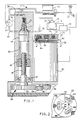
- the anti-lock braking system (ABS) 7 of the present invention includes a master cylinder 12 for supplying pressurized fluid. Connected on a wheel 14 and schematically shown, is a fluid activated wheel brake cylinder 16 (hereinafter referred to as a wheel brake) which receives pressurized fluid from the master cylinder 12 for restraining rotational movement of the wheel 14.
- the wheel brake 16 may be a conventional drum or disc type vehicle brake.
- a brake pedal 22 controlled by the vehicle operator actuates the master cylinder 12.
- An (electronic) controller 18 is also provided.
- a sensor 20 (tied into the electronic controller 18) in the wheel brake 16 determines rotational speed of the wheel 14.
- a sensor (not shown) determines whether or not the brake pedal 22 of the vehicle is being operated and also reports the information to the electronic controller 18.
- the electronic controller 18 will be cognizant of the rotational condition of the wheel 14 and will provide an appropriate signal in response thereto. The signal will place the anti-lock braking system 7 in an ABS mode of operation if the condition of the wheel 14 is within preset parameters.
- An actuator 26 is provided having an actuator body 30 with a longitudinal bore 32. (As shown, the actuator 26 is connected with one wheel brake 16, but a vehicle may have actuators connected to more than one wheel brake or actuators for each single wheel for individualized ABS response).
- the longitudinal bore 32 has a first fluid passage 42 allowing fluid communication between the wheel brake 16 and the longitudinal bore 32, and also has fluid communication with the master cylinder 12 when the solenoid valve 24 is not activated to the closed position via second fluid passage 40.
- the longitudinal bore 32 has an alternative fluid communitative path with the master cylinder 12 by way of third fluid passage 34. Fluid flow passes over a transverse slot (not shown) of a piston 44. However the solenoid valve 24 could directly tie into the wheel brake 16 and first fluid passage 42 could "T" into that line.
- the third fluid passage 34 has a check valve 38 for interrupting fluid flow between the master cylinder 12 and the wheel brake 16. The check valve 38 also allows delivery of fluid back to the master cylinder 12 whenever the wheel brake 16 has a pressure greater than that in the master cylinder 12. Therefore, the anti-lock braking system 7 is sensitive to an operator relieving the wheel brake 16 by removing his or her foot from the brake pedal 22 without any needed input from the electronic controller 18.
- the piston 44 is slidably and sealably mounted within the longitudinal bore 32. Movement of the piston 44 provides a variable control volume in communication with the wheel brake 16, thereby modulating the pressure therein.
- a nut 46 is connected with the piston 44 and the nut 46 is slidably mounted within the longitudinal bore 32 in a non-rotative fashion.
- a power screw 48 projects into the nut 46 and is threadably engaged therewith in an efficient manner.
- the power screw 48 has a fixed rotational axis with respect to the actuator body 30. Powering the power screw 48 is a (reversible) DC motor 50 which is responsive to the signals given to it by the electronic controller 18. In the position shown, for normal braking operation, the piston 44 is held at the extreme up position and must be held within a tolerance of 0.762 mm (3/100 of an inch) to maintain the check valve 38 in the open position via a rod 52 (tolerances shown in Figure 1 are greatly enlarged for purposes of illustration).
- the power screw 48 is connected to a gear train 80 which is in turn also connected with the DC motor 50.
- the power screw 48 is mounted by a bearing 54 and has a first (large) gear 82 connected to the end thereto.
- the first (large) gear 82 meshes with an idler gear 84 which in turn meshes with a (smaller) pinion gear 86.
- the pinion gear 86 axially floats on one end of a rotor 88 of the DC motor 50 and is held on by a spring clip (not shown).
- the power screw 48 along with the gear train 80 and the (non-rotative) nut 46 provide the means to reciprocally move the piston 44 within the longitudinal bore 32 and the DC motor 50 is torsionally connected via the gear train 80 to move the piston 44.
- Surrounding the DC motor 50 is a housing 56.
- a (three-lobe) disc 60 On the opposite end of the housing 56 to the gear train 80 is a (three-lobe) disc 60.
- the three-lobe disc 60 is connected with (keyed to) the other end of the rotor 88.
- the three-lobe disc 60 has three generally oval apertures 62 geometrically spaced. Inserted within these oval apertures 62 are brake pads 64 which are slightly smaller than the oval apertures and can therefore float relative to the three-lobe disc 60.
- the brake pads 64 will preferably be a canvas phenolic resin impregnated laminate which tends to provide high levels of durability in usage.
- the three-lobe disc 60 (typically fabricated out of stainless steel) also has towards its middle portion a series of geometric dimples 66, 68 which are stamped out. Three dimples 66 are pressed outward in a direction towards the housing 56, and three dimples 68 are pressed outward in a direction away from the housing 56. Therefore, when the DC motor 50 is turning during operation of the anti-lock braking system 7, the dimples 66 tend to prevent the outer portions of the three-lobe disc 60 from contacting the housing 56 thereby reducing friction with the same. In like manner, the other dimples 68 can provide a contact surface with a plunger 90 to also reduce friction with the same.
- the plunger 90 which is located on the opposite side of the three-lobe disc 60 to the housing 56, and the surface of the housing 56 adjacent the three-lobe disc cooperate to provide friction surfaces for engagement with the brake pads 64 of the three-lobe disc 60 to restrain rotation thereof, thereby braking the DC motor 50 and restraining movement of the piston 44 within the longitudinal bore 32.
- the plunger 90 is biased by a coil spring 92 to a position to urge the friction surfaces into engagement with the brake pads 64 of the three-lobe disc 60.
- an electromagnetic core 70 which is responsive to a signal given by the electronic controller 18 to move the plunger 90 to a position allowing for removal of engagement of the friction surfaces with the brake pads 64 of the three-lobe disc 60, and thereby allowing free movement of DC motor 50 and of the piston 44 within the longitudinal bore 32.
- the electromagnetic core 70 comprises a coil 72. To minimize the weight of the ABS 7 and also to minimize the space displacement of the ABS, it is desirable to keep the electromagnetic core 70 as small as possible. Also it is desirable to keep the air gap as small as possible between the electromagnetic core 70 and the plunger 90 to provide a fast response typically in the area of 5 to 8 milliseconds.
- the coil 72 is mounted within the electromagnetic core 70 in a plastic snap-in bobbin 74. It has been shown to be preferable that the stator of the electromagnetic core be comprised of a phosphorous 45% sintered metal having a density of 6.8 to 7.2 grams per cubic centimeter to help reduce eddy currents. In operation, typically the air gap at its maximum will be of the order of 0.254 mm (1/100 of an inch).
- the thickness of the brake pad 64 (sometimes referred to as shoes) will be greater than that of the three-lobe disc 60 even with the added dimension of the dimples 66 and 68. Therefore, when the plunger 90 is released into a position to brake the DC motor 50 (no current in the coil 72), the brake pads 64 will be compressed by the plunger 90 against the housing 56, and a dual braking will be achieved. This is much more efficient than utilizing a brake pad 64 which will be placed on the underside of the three-lobe disc 60 and which would only engage with the top of the housing 56.
- the brake pads 64 can float (move) within their respective apertures 62, and the three-lobe disc may move to come into engagement with the housing 56 or the plunger.
- the dimples 66,68 prevent full surface-to-surface contact, thereby reducing friction.
- the present invention provides an ABS 7 which has a path from the master cylinder 12 to the wheel brake 16 other than through the solenoid valve 24. This allows the wheel brakes 16 to be applied in the case of solenoid valve 24 failure.
- fluid from the master cylinder 12 can go past the check valve 38 and/or through the solenoid valve 24 into the longitudinal bore 32 and then out to the wheel brake 16.
- Build up of fluid pressure in the longitudinal bore 32 will tend to act on the piston 44 to try to move it downwards ( Figure 1).
- the electromagnetic brake provided by the three-lobe disc 60, electromagnetic core 70, and plunger 90 act to prevent rotation of the rotor 88, thereby preventing rotation of the gear train 80 and power screw 44, thereby holding the piston 44 in position.
- the solenoid valve 24 is closed.
- the piston 44 is moved by the DC motor 50 to close the check valve 38 and then, to vary the volume of a control volume defined by part of the longitudinal bore 32 to modulate the fluid pressure applied to the wheel brake 16.
- the plunger 90 is pulled away from the three-lobe disc 60 and the brake pads 64 float within the apertures 62, and the dimples 66,68 act to prevent full surface contact between the three-lobe disc 60 and the plunger 90 or housing 56, thereby lowering any possible friction generated when ABS is operating.
- the plunger 90 When it is desired to lock the piston 44 in position, the plunger 90 is released and due to the bias of coil spring 92, will move to trap the brake pads 64 between the plunger 90 and the housing 56, to lock the rotor 88.
- the present invention is not restricted to the shape of disc 60 and apertures 62 described above, and any other suitable shapes may be used.
Landscapes
- Physics & Mathematics (AREA)
- Engineering & Computer Science (AREA)
- Electromagnetism (AREA)
- Power Engineering (AREA)
- Fluid Mechanics (AREA)
- Transportation (AREA)
- Mechanical Engineering (AREA)
- Regulating Braking Force (AREA)
Applications Claiming Priority (2)
| Application Number | Priority Date | Filing Date | Title |
|---|---|---|---|
| US352971 | 1989-05-17 | ||
| US07/352,971 US5000523A (en) | 1989-05-17 | 1989-05-17 | Anti-lock braking system with electromagnetic brake |
Publications (2)
| Publication Number | Publication Date |
|---|---|
| EP0398531A1 true EP0398531A1 (de) | 1990-11-22 |
| EP0398531B1 EP0398531B1 (de) | 1993-09-29 |
Family
ID=23387222
Family Applications (1)
| Application Number | Title | Priority Date | Filing Date |
|---|---|---|---|
| EP90304572A Expired - Lifetime EP0398531B1 (de) | 1989-05-17 | 1990-04-26 | Antiblockier-Bremssystem |
Country Status (5)
| Country | Link |
|---|---|
| US (1) | US5000523A (de) |
| EP (1) | EP0398531B1 (de) |
| JP (1) | JPH035265A (de) |
| CA (1) | CA2010643C (de) |
| DE (1) | DE69003591T2 (de) |
Cited By (6)
| Publication number | Priority date | Publication date | Assignee | Title |
|---|---|---|---|---|
| FR2672557A1 (fr) * | 1991-02-08 | 1992-08-14 | Daimler Benz Ag | Systeme antiblocage. |
| US5385394A (en) * | 1993-05-11 | 1995-01-31 | General Motors Corporation | Antilock brake system with controlled pressure augmentation |
| WO1995028307A1 (de) * | 1994-04-19 | 1995-10-26 | Itt Automotive Europe Gmbh | Elektronisch regelbares bremsbetätigungssystem |
| WO1999027270A1 (de) * | 1997-11-21 | 1999-06-03 | Continental Teves Ag & Co. Ohg | Elektromechanisch betätigbare scheibenbremse |
| US6230492B1 (en) | 1996-08-30 | 2001-05-15 | Kelsey-Hayes Company | Electrically actuated hydraulic power cylinder |
| BE1024889B1 (nl) * | 2017-01-12 | 2018-08-21 | Lmj Construct Cvba | Remsysteem |
Families Citing this family (18)
| Publication number | Priority date | Publication date | Assignee | Title |
|---|---|---|---|---|
| US5147116A (en) * | 1991-06-28 | 1992-09-15 | General Motors Corporation | Integral ABS and traction control having an electric modulator |
| US5333706A (en) * | 1991-10-22 | 1994-08-02 | Akebono Brake Industry Co., Ltd. | Brake apparatus for a vehicle |
| JPH06191386A (ja) * | 1992-09-14 | 1994-07-12 | Aisin Seiki Co Ltd | アンチロックブレーキ制御方法及びアンチロックブレーキ制御装置 |
| US5439278A (en) * | 1993-08-23 | 1995-08-08 | Nissan Motor Co., Ltd. | Cam actuated anti-lock braking system modulator |
| US5573314A (en) * | 1995-02-22 | 1996-11-12 | Imra America, Inc. | Hydraulic brake system with arrangement for improving the brake actuation response time |
| GB2324843B (en) * | 1996-02-15 | 2000-05-17 | Kelsy Hayes Company | Brake actuation mechanism |
| US5775782A (en) * | 1996-02-23 | 1998-07-07 | Imra America, Inc. | Self-energizing vehicle brake system with control arrangement for eliminating brake pad friction fluctuation affects |
| WO1997046408A1 (en) * | 1996-06-05 | 1997-12-11 | Kelsey Hayes Company | Programmable electronic pedal simulator |
| US5775467A (en) * | 1996-07-29 | 1998-07-07 | General Motors Corporation | Floating electromagnetic brake system |
| US5927825A (en) * | 1996-12-09 | 1999-07-27 | General Motors Corporation | Electro-hydraulic brake apply system with emulator latch |
| US6082831A (en) * | 1998-04-22 | 2000-07-04 | General Motors Corporation | Electro-hydraulic brake apply system displacement augmentation |
| US6336530B1 (en) | 2000-04-07 | 2002-01-08 | Timothy L. Hottle | Vehicle brake assembly |
| KR100383077B1 (ko) * | 2000-08-02 | 2003-05-12 | 정명길 | 게르마늄수 농축분말 제조방법 및 그 장치 |
| US6578933B2 (en) * | 2001-04-24 | 2003-06-17 | Delphi Technologies, Inc. | Vehicle brake by wire actuator |
| JP5840676B2 (ja) * | 2010-04-12 | 2016-01-06 | シェフラー テクノロジーズ アー・ゲー ウント コー. カー・ゲーSchaeffler Technologies AG & Co. KG | ハイドロスタティックアクチュエータ及び自動車におけるハイドロスタティックアクチュエータのアセンブリ |
| CN103174698B (zh) * | 2011-12-26 | 2017-04-12 | 德昌电机(深圳)有限公司 | 电液执行器 |
| CN111288094B (zh) * | 2018-12-07 | 2021-05-25 | 上海汽车集团股份有限公司 | 电子离合器及其分离系统 |
| WO2021221143A1 (ja) * | 2020-04-30 | 2021-11-04 | 株式会社アドヴィックス | 制動装置 |
Citations (6)
| Publication number | Priority date | Publication date | Assignee | Title |
|---|---|---|---|---|
| GB987101A (en) * | 1961-07-07 | 1965-03-24 | Globe Ind Inc | Electromagnetic brake |
| US3195692A (en) * | 1963-01-29 | 1965-07-20 | Ortlinghaus Geb | Fluid pressure released brake |
| DE1916662A1 (de) * | 1969-04-01 | 1970-10-08 | Baezold Karl | Stellvorrichtung fuer Bremsschlupfregler |
| WO1986005028A1 (en) * | 1985-02-20 | 1986-08-28 | Zahnradfabrik Friedrichshafen Ag | Annular magnet for motor brakes |
| US4653815A (en) * | 1985-10-21 | 1987-03-31 | General Motors Corporation | Actuating mechanism in a vehicle wheel brake and anti-lock brake control system |
| EP0262102A1 (de) * | 1986-09-26 | 1988-03-30 | FIAT AUTO S.p.A. | Einrichtung zur wahlweisen Bremsdruckeinsteuerung in die Fahrzeugbremse zur Verhinderung des Radblockierens |
Family Cites Families (13)
| Publication number | Priority date | Publication date | Assignee | Title |
|---|---|---|---|---|
| US3549210A (en) * | 1969-02-14 | 1970-12-22 | Kelsey Hayes Co | Skid control system |
| FR2135689A5 (de) * | 1971-03-09 | 1972-12-22 | Potain Sa | |
| FR2149017A5 (de) * | 1971-08-06 | 1973-03-23 | Potain Sa | |
| US4308943A (en) * | 1980-04-14 | 1982-01-05 | Anchor Hocking Corporation | Liquor flask orienter |
| US4589534A (en) * | 1983-02-04 | 1986-05-20 | Institutal De Cercetare Stintifica Si Inginerie Technologica Pentrj Industria Electrotehnica | Electromechanical driving system with variable speed |
| DE3322422A1 (de) * | 1983-06-22 | 1985-01-03 | Alfred Teves Gmbh, 6000 Frankfurt | Hydraulische bremsanlage mit einer blockierschutzeinrichtung |
| EP0209943B1 (de) * | 1985-07-26 | 1992-11-11 | Mavilor Systèmes S.A. | Elektromotor mit Scheibenbremse |
| JPH0657525B2 (ja) * | 1986-03-12 | 1994-08-03 | 本田技研工業株式会社 | アンチロツクブレ−キ装置 |
| US4659970A (en) * | 1986-08-14 | 1987-04-21 | Caterpillar Industrial Inc. | Vehicle docking apparatus and method |
| DE3873822D1 (de) * | 1987-05-22 | 1992-09-24 | Teves Gmbh Alfred | Bremsanlage mit blockierschutz- und/oder antriebsschlupfregelung sowie bremsdruckmodulator fuer eine solche bremsanlage. |
| US4756391A (en) * | 1987-07-06 | 1988-07-12 | General Motors Corporation | Brake system actuator with a return spring |
| DE3723876A1 (de) * | 1987-07-18 | 1989-01-26 | Daimler Benz Ag | Sicherheitseinrichtung fuer ein mit einem antiblockiersystem ausgeruestetes strassenfahrzeug |
| US4835695A (en) * | 1987-11-13 | 1989-05-30 | General Motors Corporation | Add-on vehicle wheel slip controller |
-
1989
- 1989-05-17 US US07/352,971 patent/US5000523A/en not_active Expired - Lifetime
-
1990
- 1990-02-22 CA CA002010643A patent/CA2010643C/en not_active Expired - Fee Related
- 1990-04-26 DE DE90304572T patent/DE69003591T2/de not_active Expired - Fee Related
- 1990-04-26 EP EP90304572A patent/EP0398531B1/de not_active Expired - Lifetime
- 1990-05-17 JP JP2125608A patent/JPH035265A/ja active Pending
Patent Citations (6)
| Publication number | Priority date | Publication date | Assignee | Title |
|---|---|---|---|---|
| GB987101A (en) * | 1961-07-07 | 1965-03-24 | Globe Ind Inc | Electromagnetic brake |
| US3195692A (en) * | 1963-01-29 | 1965-07-20 | Ortlinghaus Geb | Fluid pressure released brake |
| DE1916662A1 (de) * | 1969-04-01 | 1970-10-08 | Baezold Karl | Stellvorrichtung fuer Bremsschlupfregler |
| WO1986005028A1 (en) * | 1985-02-20 | 1986-08-28 | Zahnradfabrik Friedrichshafen Ag | Annular magnet for motor brakes |
| US4653815A (en) * | 1985-10-21 | 1987-03-31 | General Motors Corporation | Actuating mechanism in a vehicle wheel brake and anti-lock brake control system |
| EP0262102A1 (de) * | 1986-09-26 | 1988-03-30 | FIAT AUTO S.p.A. | Einrichtung zur wahlweisen Bremsdruckeinsteuerung in die Fahrzeugbremse zur Verhinderung des Radblockierens |
Cited By (7)
| Publication number | Priority date | Publication date | Assignee | Title |
|---|---|---|---|---|
| FR2672557A1 (fr) * | 1991-02-08 | 1992-08-14 | Daimler Benz Ag | Systeme antiblocage. |
| US5385394A (en) * | 1993-05-11 | 1995-01-31 | General Motors Corporation | Antilock brake system with controlled pressure augmentation |
| WO1995028307A1 (de) * | 1994-04-19 | 1995-10-26 | Itt Automotive Europe Gmbh | Elektronisch regelbares bremsbetätigungssystem |
| US6230492B1 (en) | 1996-08-30 | 2001-05-15 | Kelsey-Hayes Company | Electrically actuated hydraulic power cylinder |
| WO1999027270A1 (de) * | 1997-11-21 | 1999-06-03 | Continental Teves Ag & Co. Ohg | Elektromechanisch betätigbare scheibenbremse |
| US6315092B1 (en) | 1997-11-21 | 2001-11-13 | Continental Teves Ag & Co., Ohg | Electromechanically actuated disc brake |
| BE1024889B1 (nl) * | 2017-01-12 | 2018-08-21 | Lmj Construct Cvba | Remsysteem |
Also Published As
| Publication number | Publication date |
|---|---|
| JPH035265A (ja) | 1991-01-11 |
| DE69003591D1 (de) | 1993-11-04 |
| CA2010643C (en) | 1994-08-02 |
| EP0398531B1 (de) | 1993-09-29 |
| US5000523A (en) | 1991-03-19 |
| CA2010643A1 (en) | 1990-11-17 |
| DE69003591T2 (de) | 1994-01-20 |
Similar Documents
| Publication | Publication Date | Title |
|---|---|---|
| EP0398531B1 (de) | Antiblockier-Bremssystem | |
| US5112116A (en) | Anti-lock braking system with electromagnetic brake | |
| JP3541621B2 (ja) | 車両用制動装置 | |
| US4435021A (en) | Vehicle brake actuator and braking system | |
| US4756391A (en) | Brake system actuator with a return spring | |
| US6328388B1 (en) | Brake actuation unit | |
| US7552978B2 (en) | Brake device and controller for the same | |
| EP0699147A1 (de) | Hydraulische bremsanlage mit schlupfregelung | |
| EP2837847B1 (de) | Scheibenbremse | |
| US5462343A (en) | Hydraulic pressure booster having booster piston and valve mechanism associated with mechanically operated and electrically controlled pressure regulators | |
| DE69832222T2 (de) | Fahrzeugbremsanlage mit einem Reservoir zur Aufnahme von aus einem Radbremszylinder über eine Drucksteuerventileinrichtung abgelassener Flüssigkeit | |
| WO1992017355A1 (de) | Hydraulische bremsanlage mit blockierschutz- und antriebschlupfregelung | |
| CA1297139C (en) | Traction system utilizing pump back based abs system | |
| EP0358797B1 (de) | Betätiger für Drosselöffnungssteuerung | |
| EP0398532B1 (de) | Blockierschutz-Bremssystem | |
| US5147114A (en) | Electrically controllable pressure medium brake for vehicles | |
| US4691813A (en) | Friction clutch operated pressure modulator | |
| JPH09512764A (ja) | 自動車用流体ブレーキ回路のためのハイブリッド構造をもつ圧力調整装置 | |
| EP0520526A1 (de) | Integrierte Brems- und Antriebsschlupfregeleinrichtung | |
| JPH07156770A (ja) | 制動力制御装置 | |
| GB2293364A (en) | Industrial Lift Truck | |
| CN111717180B (zh) | 具有真空操作型辅助装置的机动车辆制动系统 | |
| JP2000233735A (ja) | 磁歪ブレーキ作動機構 | |
| EP1516795B1 (de) | System für das Regeln der Leistungsversorgung eines Bremssystems | |
| CA2009015A1 (en) | Cam modulator for anti-lock braking system apparatus and method |
Legal Events
| Date | Code | Title | Description |
|---|---|---|---|
| PUAI | Public reference made under article 153(3) epc to a published international application that has entered the european phase |
Free format text: ORIGINAL CODE: 0009012 |
|
| AK | Designated contracting states |
Kind code of ref document: A1 Designated state(s): DE FR GB IT |
|
| 17P | Request for examination filed |
Effective date: 19901212 |
|
| 17Q | First examination report despatched |
Effective date: 19920601 |
|
| GRAA | (expected) grant |
Free format text: ORIGINAL CODE: 0009210 |
|
| ITF | It: translation for a ep patent filed |
Owner name: BARZANO' E ZANARDO ROMA S.P.A. |
|
| AK | Designated contracting states |
Kind code of ref document: B1 Designated state(s): DE FR GB IT |
|
| REF | Corresponds to: |
Ref document number: 69003591 Country of ref document: DE Date of ref document: 19931104 |
|
| ET | Fr: translation filed | ||
| PLBE | No opposition filed within time limit |
Free format text: ORIGINAL CODE: 0009261 |
|
| STAA | Information on the status of an ep patent application or granted ep patent |
Free format text: STATUS: NO OPPOSITION FILED WITHIN TIME LIMIT |
|
| 26N | No opposition filed | ||
| ITTA | It: last paid annual fee | ||
| PGFP | Annual fee paid to national office [announced via postgrant information from national office to epo] |
Ref country code: GB Payment date: 19980323 Year of fee payment: 9 |
|
| PGFP | Annual fee paid to national office [announced via postgrant information from national office to epo] |
Ref country code: FR Payment date: 19980428 Year of fee payment: 9 |
|
| PGFP | Annual fee paid to national office [announced via postgrant information from national office to epo] |
Ref country code: DE Payment date: 19980616 Year of fee payment: 9 |
|
| PG25 | Lapsed in a contracting state [announced via postgrant information from national office to epo] |
Ref country code: GB Free format text: LAPSE BECAUSE OF NON-PAYMENT OF DUE FEES Effective date: 19990426 |
|
| GBPC | Gb: european patent ceased through non-payment of renewal fee |
Effective date: 19990426 |
|
| PG25 | Lapsed in a contracting state [announced via postgrant information from national office to epo] |
Ref country code: FR Free format text: LAPSE BECAUSE OF NON-PAYMENT OF DUE FEES Effective date: 19991231 |
|
| REG | Reference to a national code |
Ref country code: FR Ref legal event code: ST |
|
| PG25 | Lapsed in a contracting state [announced via postgrant information from national office to epo] |
Ref country code: DE Free format text: LAPSE BECAUSE OF NON-PAYMENT OF DUE FEES Effective date: 20000201 |
|
| PG25 | Lapsed in a contracting state [announced via postgrant information from national office to epo] |
Ref country code: IT Free format text: LAPSE BECAUSE OF NON-PAYMENT OF DUE FEES;WARNING: LAPSES OF ITALIAN PATENTS WITH EFFECTIVE DATE BEFORE 2007 MAY HAVE OCCURRED AT ANY TIME BEFORE 2007. THE CORRECT EFFECTIVE DATE MAY BE DIFFERENT FROM THE ONE RECORDED. Effective date: 20050426 |