EP0397596A1 - Ultraschall-Durchflussmessgerät - Google Patents
Ultraschall-Durchflussmessgerät Download PDFInfo
- Publication number
- EP0397596A1 EP0397596A1 EP90810317A EP90810317A EP0397596A1 EP 0397596 A1 EP0397596 A1 EP 0397596A1 EP 90810317 A EP90810317 A EP 90810317A EP 90810317 A EP90810317 A EP 90810317A EP 0397596 A1 EP0397596 A1 EP 0397596A1
- Authority
- EP
- European Patent Office
- Prior art keywords
- conductive
- converter
- input
- conducting
- switching
- Prior art date
- Legal status (The legal status is an assumption and is not a legal conclusion. Google has not performed a legal analysis and makes no representation as to the accuracy of the status listed.)
- Granted
Links
- 239000004065 semiconductor Substances 0.000 claims abstract description 12
- 239000012530 fluid Substances 0.000 claims description 12
- 238000005259 measurement Methods 0.000 claims description 6
- 230000005669 field effect Effects 0.000 description 5
- 230000005540 biological transmission Effects 0.000 description 1
- 238000010586 diagram Methods 0.000 description 1
- 230000005284 excitation Effects 0.000 description 1
- 239000000463 material Substances 0.000 description 1
- 230000010355 oscillation Effects 0.000 description 1
Images
Classifications
-
- G—PHYSICS
- G01—MEASURING; TESTING
- G01F—MEASURING VOLUME, VOLUME FLOW, MASS FLOW OR LIQUID LEVEL; METERING BY VOLUME
- G01F1/00—Measuring the volume flow or mass flow of fluid or fluent solid material wherein the fluid passes through a meter in a continuous flow
- G01F1/66—Measuring the volume flow or mass flow of fluid or fluent solid material wherein the fluid passes through a meter in a continuous flow by measuring frequency, phase shift or propagation time of electromagnetic or other waves, e.g. using ultrasonic flowmeters
- G01F1/663—Measuring the volume flow or mass flow of fluid or fluent solid material wherein the fluid passes through a meter in a continuous flow by measuring frequency, phase shift or propagation time of electromagnetic or other waves, e.g. using ultrasonic flowmeters by measuring Doppler frequency shift
-
- G—PHYSICS
- G01—MEASURING; TESTING
- G01F—MEASURING VOLUME, VOLUME FLOW, MASS FLOW OR LIQUID LEVEL; METERING BY VOLUME
- G01F1/00—Measuring the volume flow or mass flow of fluid or fluent solid material wherein the fluid passes through a meter in a continuous flow
- G01F1/66—Measuring the volume flow or mass flow of fluid or fluent solid material wherein the fluid passes through a meter in a continuous flow by measuring frequency, phase shift or propagation time of electromagnetic or other waves, e.g. using ultrasonic flowmeters
- G01F1/667—Arrangements of transducers for ultrasonic flowmeters; Circuits for operating ultrasonic flowmeters
Definitions
- the invention relates to ultrasonic flowmeters, as described for example in US-A 37 51 979. 3 and 10, along a fluid measurement path, e.g. a tube, a pair of opposing ultrasonic transducers, hereinafter referred to as US transducers, arranged, the connecting line of which forms an angle deviating from 90 degrees with the longitudinal axis of the fluid measurement path.
- a fluid measurement path e.g. a tube
- US transducers e.g. a pair of opposing ultrasonic transducers, hereinafter referred to as US transducers, arranged, the connecting line of which forms an angle deviating from 90 degrees with the longitudinal axis of the fluid measurement path.
- the US transducers are alternately switched from sending to receiving, so that the sound waves propagate in the fluid with a component in the direction of its flow and the other with a component in the direction of its flow.
- the sinusoidal excitation of the US transducer serving as an ultrasonic transmitter is usually carried out by means of an oscillator circuit at a frequency of a few 10 kHz.
- the switchover takes place in such a way that two switching paths are provided for each US converter, one of which is simultaneously controlled to be conductive and the other to be non-conductive, or vice versa.
- the respective end of the two switching paths is connected to the associated US converter and the other end of the conductive switching path assigned to one US converter is located at the other end of the non-conductive switching path assigned to the other US converter and at the input of a measuring circuit, while the other end of the a non-conductive switching path assigned to a US converter is connected to the other end of the conductive switching path assigned to the other US converter and to the output of the aforementioned oscillator circuit.
- the object of the invention defined in the patent claims is to reduce this crosstalk by means of circuitry measures in such a way that the still remaining Crosstalk interference signal can be accepted, in other words, the existing crosstalk attenuation of the usual semiconductor analog switches, which is approximately 65 dB at 50 kHz and a terminating resistor of 600 ohms, should be increased at least ten times.
- an analog switchover arrangement type is selected that has two non-conductive additional switching paths, which must be implemented on the same semiconductor chip and in the same semiconductor technology as the switching paths, which therefore, like the switching paths, e.g. CMOS switches are.
- the two additional switching paths are also connected in parallel with one another and continuously controlled in a non-conductive manner. So if e.g. an analog switchover arrangement type is used in which switching paths are already non-conductive without a control signal, their control input can remain unconnected.
- this parallel connection of the two additional switching paths is in series with an inverting standard amplifier, i.e. a 180 degree phase-rotating analog amplifier with gain one, and this series connection is between the oscillator output and the measuring circuit input or between the two US converters.
- a flow meter realized using the analog switch type DG 307 A from Siliconix had the same Measurement conditions as above, i.e. 50 kHz and 600 ohms, already have a crosstalk attenuation of about 100 dB, which far exceeded the expectations.
- the two US converters w1, w2 are placed around the fluid measuring path ms, which consists of a tube made of a suitable material in which the fluid to be measured flows.
- the angle between the connecting line of the two US converters w1 and w2 and the flow direction is therefore 0 degrees.
- the invention is not limited to this preferred arrangement of the US transducers, but rather the arrangements familiar from the prior art mentioned, in which the US transducers are attached at the edge of the fluid measurement section at an angle opposite one another, are also possible.
- the integrated analog switchover arrangement sw consists of the two switching paths s11, s12 assigned to a US converter w1, one of which is non-conductive when the other is conductive.
- the graphic representation is chosen so that a mechanical normally open contact is shown for the non-conductive switching paths, whereas a mechanical normally closed contact is shown for the conductive switching paths.
- the control signal is direct to the transistor realizing the non-conducting switching path, to the transistor realizing the simultaneously conducting switching path on the other hand, fed via an inverter.
- the non-conductive switching path s11 and the conductive switching path s12 are assigned to the US converter w1 in such a way that in each case one of their connections is connected to the one connection of the US converter w1, the other of which lies at the circuit zero.
- the other US converter w2 includes the non-conductive switching path s21 and the conductive switching path s22, one end of which lies at a connection of the US converter w2, the other end of which is connected to the circuit zero.
- the other ends of the switching paths s11, s22 are at the output of the oscillator circuit os, which generates the alternating voltage signal which generates the ultrasonic oscillation.
- the other ends of the switching paths s12, s21 are at the input of the measuring circuit m, which are measured in the usual way from those measured in the flow direction and in the counterflow direction Runtimes generates a signal representing the flow velocity of the fluid.
- the two permanently nonconducting additional switching paths z1, z2 are connected in parallel with one another, so that the inverting unit amplifier ew is in series with this parallel connection in such a way that the oscillator signal is rotated by 180 degrees is supplied, and that this series circuit lies between the output of the oscillator circuit os and the input of the measuring circuit m.
- a correspondingly connected operational amplifier is used for implementation.
- the additional switching paths z1, z2 are to be implemented in the same semiconductor technology and on the same semiconductor chip as the switching paths s ... so that they have largely identical electrical properties with them.
Landscapes
- Physics & Mathematics (AREA)
- Electromagnetism (AREA)
- Fluid Mechanics (AREA)
- General Physics & Mathematics (AREA)
- Measuring Volume Flow (AREA)
- Ultra Sonic Daignosis Equipment (AREA)
Abstract
Description
- Die Erfindung betrifft Ultraschall-Durchflussmessgeräte, wie sie beispielsweise in der US-A 37 51 979 beschrieben sind. Nach deren Fig. 3 und 10 ist entlang einer Fluidmessstrecke, z.B. eines Rohres, ein Paar von gegenüberliegenden Ultraschallwandlern, im folgenden kurz US-Wandler genannt, angeordnet, deren Verbindungslinie mit der Längsachse der Fluidmessstrecke einem von 90 Grad abweichenden Winkel bildet.
- Zur Erzielung eines von der Schallgeschwindigkeit im Fluid unabhängigen Messergebnisses werden die US-Wandler abwechselnd von Senden auf Empfangen umgeschaltet, so dass die Schallwellen sich im Fluid das eine Mal mit einer Komponenten in seiner Strömungsrichtung und das andere Mal mit einer Komponenten entgegen seiner Strömungsrichtung ausbreiten.
- Nach Fig. 6 der genannten US-A 37 51 979 werden die US-Wandler des Paares mittels einer elektronischen Schaltung, die Torschaltungen enthält, umgeschaltet. Anstatt dieser speziellen elektronischen Schaltung können zur Umschaltung auch inzwischen handelsübliche integrierte Halbleiter-Analogumschaltanordnungen verwendet werden, wie z.B. die verschiedenen von der Fa. Siliconix angebotenen CMOS Analog Switches, die pro Chip mehrere Schaltstrecken aufweisen.
- Die sinusförmige Erregung des als Ultraschallsender dienenden US-Wandlers erfolgt mittels einer Oszillatorschaltung üblicherweise bei einer Frequenz von einigen 10 kHz. Die Umschaltung erfolgt so, dass pro US-Wandler zwei Schaltstrecken vorgesehen sind, von denen jeweils gleichzeitig die eine leitend und die andere nichtleitend gesteuert wird oder umgekehrt. Dabei liegt das jeweilige Ende der beiden Schaltstrecken am zugeordneten US-Wandler und das andere Ende der dem einen US-Wandler zugeordneten leitenden Schaltstrecke am anderen Ende der dem anderen US-Wandler zugeordneten nichtleitenden Schaltstrecke sowie am Eingang einer Messschaltung, während das andere Ende der dem einen US-Wandler zugeordneten nichtleitenden Schaltstrecke mit dem anderen Ende der dem anderen US-Wandler zugeordneten leitenden Schaltstrecke und mit dem Ausgang der erwähnten Oszillatorschaltung verbunden ist.
- Es hat sich nun gezeigt, dass bei der Verwendung der genannten handelsüblichen integrierten Analogumschaltanordnungen ein Uebersprechen auftritt, das von den nichtleitenden Schaltstrecken ausgeht, da sie u.a. eine Längskapazität aufweisen bzw. bilden, also eine Kapazität, die zwischen dem Analogsignal-Eingang und dem Analogsignal-Ausgang liegt.
- Die Aufgabe der in den Patentansprüchen definierten Erfindung besteht darin, dieses Uebersprechen durch schaltungstechnische Massnahmen so zu reduzieren, dass das trotzdem noch verbleibende Uebersprech-Störsignal akzeptiert werden kann, mit andern Worten soll die an sich vorhandene Uebersprechdämpfung der üblichen Halbleiter-Analogschalter, die bei z.B. 50 kHz und einem Abschlusswiderstand von 600 Ohm ca. 65 dB beträgt, um mindestens stens das Zehnfache erhöht werden.
- Dies wird bei der Erfindung zum einen dadurch erreicht, dass ein Analogumschaltanordnungs-Typ ausgewählt wird, der zwei nichtleitende Zusatzschaltstrecken aufweist, die auf demselben Halbleiterchip und in derselben Halbleitertechnologie wie die Schaltstrecken realisiert sein müssen, die also ebenso wie die Schaltstrecken z.B. CMOS-Schalter sind. Die beiden Zusatzschaltstrecken sind nach der Erfindung ferner einander parallelgeschaltet und dauernd nichtleitend gesteuert. Wenn also z.B. ein Analogumschaltanordnungs-Typ verwendet wird, bei dem Schaltstrecken bereits ohne Steuersignal nichtleitend sind, kann ihr Steuereingang unbeschaltet bleiben. Schliesslich liegt diese Parallelschaltung der beiden Zusatzschaltstrecken in Serie mit einem invertierenden Einheitsverstärker, also einem um 180 Grad phasendrehenden Analogverstärker, der die Verstärkung eins hat, und diese Serienschaltung liegt zwischen dem Oszillatorausgang und dem Messschaltungseingang oder zwischen den beiden US-Wandlern.
- Ein realisiertes Durchflussmessgerät unter Verwendung des Analogschaltertyps DG 307 A von Siliconix hatte bei gleichen Messbedingungen wie oben, also 50 kHz und 600 Ohm, bereits eine Uebersprechdämpfung von etwa 100 dB, was die gestellten Erwartungen weit übertraf.
- Die Erfindung wird nun anhand der Figuren der Zeichnung weiter erläutert.
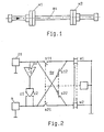
- Fig. 1 zeigt als Ausführungsbeispiel schematisch den mechanischen Teil eines Ultraschalldurchflussmessgerätes, also dessen Ultraschall-Fluidmessstrecke, und
- Fig. 2 zeigt schematisch das Schaltbild des elektronischen Teils des Ultraschalldurchflussmessgeräts.
- Beim Ausführungsbeispiel der Fig. 1 sind die beiden US-Wandler w1, w2 um die Fluidmessstrecke ms gelegt, die von einem Rohr aus geeignetem Material besteht, in dem das zu messende Fluid strömt. Der Winkel zwischen der Verbindungslinie der beiden US-Wandler w1 und w2 und der Strömungsrichtung beträgt daher 0 Grad.
- Die Erfindung ist jedoch nicht auf diese bevorzugte Anordnung der US-Wandler beschränkt, sondern es sind die aus dem genannten Stand der Technik geläufigen Anordnungen, bei denen die US-Wandler am Rand der Fluidmessstrecke einander schräg gegenüberliegend angebracht sind, ebenfalls möglich. Beim in Fig. 2 schematisch gezeigten elektronischen Teil der Erfindung besteht die integrierte Analogumschaltanordnung sw aus den beiden dem einen US-Wandler w1 zugeordneten Schaltstrecken s11, s12, von denen die eine nichtleitend ist, wenn die andere leitend ist. In Fig. 2 ist die zeichnerische Darstellung so gewählt, dass für die nichtleitenden Schaltstrecken ein mechanischer Arbeitskontakt, dagegen für die leitenden Schaltstrecken ein mechanischer Ruhekontakt gezeigt ist.
- Die beiden Funktionen "leitend", "nichtleitend" sind zum einen paarweise gleichzeitig zu realisieren und zum anderen durch ein Steuersignal zu vertauschen. Dies kann z.B. mit einem einzigen Steuersignal, dessen einer Pegel bei OV (= L-Pegel) liegt, und dessen anderer Pegel positiv ist und einige Volt (= H-Pegel) beträgt, zum einen dadurch erreicht werden, dass als nichtleitende Schaltstrecke ein N-Kanal-Enhancement-Feldeffekttransistor, der dann beim angelegten H-Pegel leitend wird, und als leitende Schaltstrecke ein N-Kanal-Depletion-Feldeffekttransistor benutzt wird, der dann beim angelegten H-Pegel gesperrt, also nichtleitend, wird, zum andern aber auch dadurch, dass als nichtleitende Schaltstrecke ein P-Kanal-Depletion-Feldeffekttransistor, der dann beim angelegten H-Pegel leitend wird, und als leitende Schaltstrecke ein P-Kanal-Enhancement-Feldeffekttransistor benutzt wird, der dann bei angelegtem H-Pegel nichtleitend wird.
- Wenn andererseits für die Schaltstrecken nur Isolierschicht-Feldeffekttransistoren desselben Leitungstyps (N-Kanal oder P-Kanal) und derselben Leitungsart (Enhancement oder Depletion) verwendet werden sollen, ist das Steuersignal dem die nichtleitende Schaltstrecke realisierenden Transistor direkt, dem die gleichzeitig leitende Schaltstrecke realisierenden Transistor dagegen über einen Inverter zuzuführen. Das eben Erläuterte gilt an sich auch für die Verwendung von CMOS-Transmission-Gates als Schaltstrecken.
- In Fig. 2 sind dem US-Wandler wl die nichtleitende Schaltstrecke s11 und die leitende Schaltstrecke s12 derart zugeordnet, dass jeweils der eine ihrer Anschlüsse mit dem einen Anschluss des US-Wandlers w1 verbunden ist, dessen anderer am Schaltungsnullpunkt liegt. In vergleichbarer Weise gehören zum anderen US-Wandler w2 die nichtleitende Schaltstrecke s21 und die leitende Schaltstrecke s22, deren jeweiliges eines Ende am einen Anschluss des US-Wandlers w2 liegt, dessen anderer mit dem Schaltungsnullpunkt verbunden ist.
- Die anderen Enden der Schaltstrecken s11, s22 liegen am Ausgang der Oszillatorschaltung os, die das die Ultraschallschwingung erzeugende Wechselspannungssignal erzeugt. Dagegen liegen die anderen Enden der Schaltstrecken s12,s21 am Eingang der Messschaltung m, die in üblicher Weise aus den in Strömungsrichtung und in Gegenströmungsrichtung gemessenen Laufzeiten ein die Strömungsgeschwindigkeit des Fluids repräsentierendes Signal erzeugt.
- Zur Lösung des eingangs geschilderten Problems des Uebersprechens ist nun entsprechend Fig. 2 vorgesehen, dass die beiden dauernd nichtleitenden Zusatzschaltstrecken z1, z2 einander parallelgeschaltet sind, dass mit dieser Parallelschaltung der invertierende Einheitsverstärker ew derart in Serie liegt, dass ihr das Oszillatorsignal um 180 Grad gedreht zugeführt wird, und dass diese Serienschaltung zwischen dem Ausgang der Oszillatorschaltung os und dem Eingang der Messschaltung m liegt. Der invertierende Einheitsverstärker hat die Verstärkung v = -1. Zur Realisierung dient ein entsprechend beschalteter Operationsverstärker.
- Die Zusatzschaltstrecken z1, z2 sind in derselben Halbleitertechnologie und auf demselben Halbleiterchip wie die Schaltstrecken s... zu realisieren, damit sie mit diesen weitestgehend identische elektrische Eigenschaften haben.
Claims (3)
- deren Verbindungslinie mit der Längsachse der Fluidmessstrecke (ms) einen von 90 Grad abweichenden Winkel bildet und
- die mittels einer integrierten Halbleiter-Analogumschaltanordnung (sw) auf Senden bzw. Empfangen einstellbar sind,
-- die pro US-Wandler (w1, w2) zwei Schaltstrecken (s11, s12; s21, s22)
--- vondenen jeweils gleichzeitig die eine(s12, s22) leitend und die andere (s11, s21) nichtleitend ist oder umgekehrt,
--- von denen jeweils das eine Ende gemeinsam am zugehörigen US-Wandler (w1, w2),
--- von denen das andere Ende der dem einen US-Wandler (W1) zugeordneten leitenden Schaltstrecke (s12) mit dem anderen Ende der dem anderen US-Wandler (w2) zugeordneten nichtleitenden Schaltstrecke (s21) sowie mit dem Eingang einer Messschaltung (m) und
--- von denen das andere Ende der dem einen US-Wandler (w1) zugeordneten nichtleitenden Schaltstrecke (s11) mit dem anderen Ende der dem anderen US-Wandler (w2) zugeordneten leitenden Schaltstrecke (s22) sowie mit dem Eingang einer Oszillatorschaltung (os) verbunden ist, und
-- zwei dauernd nichtleitende, auf demselben Halbleiterchip und in derselben Halbleitertechnologie wie die Schaltstrecken (s...) realisierte und einander parallelgeschaltete Zusatzschaltstrecken (z1, z2) aufweist,
--- welche Parallelschaltung, mit eineminvertierenden Einheitsverstärker (ev) in Serie geschaltet, zwischen dem Oszillatorausgang und dem Messschaltungseingang oder zwischen dem jeweiligen Eingang der beiden US-Wandler (w1, w2) liegt.
Applications Claiming Priority (2)
| Application Number | Priority Date | Filing Date | Title |
|---|---|---|---|
| EP89810343 | 1989-05-09 | ||
| EP89810343 | 1989-05-09 |
Publications (2)
| Publication Number | Publication Date |
|---|---|
| EP0397596A1 true EP0397596A1 (de) | 1990-11-14 |
| EP0397596B1 EP0397596B1 (de) | 1993-01-27 |
Family
ID=8203146
Family Applications (1)
| Application Number | Title | Priority Date | Filing Date |
|---|---|---|---|
| EP90810317A Expired - Lifetime EP0397596B1 (de) | 1989-05-09 | 1990-04-20 | Ultraschall-Durchflussmessgerät |
Country Status (4)
| Country | Link |
|---|---|
| US (1) | US5105666A (de) |
| EP (1) | EP0397596B1 (de) |
| JP (1) | JPH0656309B2 (de) |
| DE (1) | DE59000807D1 (de) |
Families Citing this family (16)
| Publication number | Priority date | Publication date | Assignee | Title |
|---|---|---|---|---|
| DE59100815D1 (de) * | 1991-02-08 | 1994-02-17 | Flowtec Ag | Betriebsschaltung für Ultraschall-Volumendurchflussmessgeräte. |
| JP3019741U (ja) * | 1995-06-23 | 1996-01-12 | 株式会社カケハシ | 建築用板材 |
| JP3177677B2 (ja) * | 1996-05-14 | 2001-06-18 | 松下電器産業株式会社 | 超音波連続波ドプラ血流計 |
| ATE366407T1 (de) | 1996-12-05 | 2007-07-15 | Kamstrup As | Durchflussmesser und verfahren zum betreiben eines durchflussmessers |
| US6009761A (en) * | 1997-09-03 | 2000-01-04 | Dresser Industries, Inc. | Multiproduct fuel dispenser using ultrasonic metering |
| US6158289A (en) * | 1997-10-21 | 2000-12-12 | Dresser Industries, Inc. | Multiple orifice ultrasonic meter for measuring flow of specific grades of fuel |
| DK200101581A (da) * | 2001-10-26 | 2003-04-27 | Danfoss As | Transceiverkredsløb til ultralydsflowmåler |
| US6918877B2 (en) * | 2003-08-05 | 2005-07-19 | Siemens Medical Solutions Usa, Inc. | Method and system for reducing undesirable cross talk in diagnostic ultrasound arrays |
| CN103229025B (zh) * | 2010-10-27 | 2016-06-29 | 卡姆鲁普股份有限公司 | 具有零阻抗测量电子装置的超声波流量计 |
| US8505391B1 (en) * | 2012-03-30 | 2013-08-13 | Joseph Baumoel | Flange mounted ultrasonic flowmeter |
| US9494454B2 (en) | 2013-12-06 | 2016-11-15 | Joseph Baumoel | Phase controlled variable angle ultrasonic flow meter |
| CN104864923A (zh) * | 2014-02-24 | 2015-08-26 | 通用电气公司 | 传送和接收超声信号的电路组件及使用该电路组件的系统和方法 |
| US9310236B2 (en) | 2014-09-17 | 2016-04-12 | Joseph Baumoel | Ultrasonic flow meter using reflected beams |
| US9714855B2 (en) | 2015-01-26 | 2017-07-25 | Arad Ltd. | Ultrasonic water meter |
| US9752907B2 (en) | 2015-04-14 | 2017-09-05 | Joseph Baumoel | Phase controlled variable angle ultrasonic flow meter |
| DE102018132053B4 (de) * | 2018-12-13 | 2022-08-25 | Endress+Hauser Flowtec Ag | Ultraschallwandleranordnung einer Clamp-On-Ultraschall-Durchflussmessstelle, und eine Clamp-On-Ultraschall-Durchflussmessstelle sowie Verfahren zur Inbetriebnahme der Clamp-On-Ultraschall-Durchflussmessstelle |
Citations (3)
| Publication number | Priority date | Publication date | Assignee | Title |
|---|---|---|---|---|
| US3751979A (en) * | 1971-11-17 | 1973-08-14 | Raytheon Co | Speed measurement system |
| US4164865A (en) * | 1977-02-22 | 1979-08-21 | The Perkin-Elmer Corporation | Acoustical wave flowmeter |
| EP0200896A2 (de) * | 1985-03-27 | 1986-11-12 | Badger Meter, Inc. | Digitale Schaltung für einen Durchflussmesser und Verfahren zur Durchflussmessung |
-
1990
- 1990-04-20 EP EP90810317A patent/EP0397596B1/de not_active Expired - Lifetime
- 1990-04-20 DE DE9090810317T patent/DE59000807D1/de not_active Expired - Fee Related
- 1990-04-30 US US07/516,146 patent/US5105666A/en not_active Expired - Fee Related
- 1990-05-09 JP JP2117809A patent/JPH0656309B2/ja not_active Expired - Lifetime
Patent Citations (3)
| Publication number | Priority date | Publication date | Assignee | Title |
|---|---|---|---|---|
| US3751979A (en) * | 1971-11-17 | 1973-08-14 | Raytheon Co | Speed measurement system |
| US4164865A (en) * | 1977-02-22 | 1979-08-21 | The Perkin-Elmer Corporation | Acoustical wave flowmeter |
| EP0200896A2 (de) * | 1985-03-27 | 1986-11-12 | Badger Meter, Inc. | Digitale Schaltung für einen Durchflussmesser und Verfahren zur Durchflussmessung |
Non-Patent Citations (1)
| Title |
|---|
| THE REVIEW OF SCIENTIFIC INSTRUMENTS vol. 25, no. 3, März 1954, Seiten 201 - 206; H.P. KALMUS: "Electronic flowmeter system" * |
Also Published As
| Publication number | Publication date |
|---|---|
| DE59000807D1 (de) | 1993-03-11 |
| EP0397596B1 (de) | 1993-01-27 |
| JPH0656309B2 (ja) | 1994-07-27 |
| JPH02309216A (ja) | 1990-12-25 |
| US5105666A (en) | 1992-04-21 |
Similar Documents
| Publication | Publication Date | Title |
|---|---|---|
| EP0397596B1 (de) | Ultraschall-Durchflussmessgerät | |
| DE69416129T2 (de) | Ein Verfahren zum Betrieb eines Ultraschallwandlers und Schaltungsanordnung zur Durchführung des Verfahrens | |
| DE3124979A1 (de) | "ultraschallwandler-anordnung fuer bogenabtastung" | |
| AT410596B (de) | Sende- und empfangsschaltung für ultraschall-durchflussmesser | |
| EP0236525A1 (de) | Integrierte Isolierschicht-Feldeffekttransistor-Verzögerungsleitung für Digitalsignale | |
| DE1267354B (de) | Ultraschalluebertragungsstrecke | |
| DE2238925C2 (de) | Akustisches oberflaechenwellenwandlersystem | |
| DE1000863B (de) | Elektronischer Schaltkontakt | |
| DE19651548C2 (de) | CMOS-Ausgangsschaltung mit einer Ladevorspannungsschaltung | |
| EP0498141B1 (de) | Betriebsschaltung für Ultraschall-Volumendurchflussmessgeräte | |
| DE2224497A1 (de) | Elektromechanisches Filter | |
| DE3322310A1 (de) | Oberflaechenschallwellenvorrichtung | |
| EP0150452B1 (de) | Sender-Empfänger-Vorrichtung für ein Ultraschall-Bildgerät | |
| DE19810798A1 (de) | Schaltungsanordnung zur Steuerung und Auswertung für Ultraschall-Volumenstrommeßgeräte | |
| DE2443608A1 (de) | Akustische oberflaechenwellenanordnung | |
| DE1100874B (de) | Anordnung zur Durchfuehrung von Magen- und Darmuntersuchungen mittels eines Pillensenders | |
| DE3718111C2 (de) | ||
| WO2013017397A1 (de) | Galvanisch getrennter richtkoppler | |
| DE102004026556B3 (de) | Sende- und Empfangsschaltung für ein Ultraschalldurchflußmeßgerät und Verfahren zum Betreiben einer solchen Sende- und Empfangsschaltung | |
| DE19534309C1 (de) | Anordnung zum Übertragen von Signalen über Triplate-Leitungen | |
| DE2714142A1 (de) | Einrichtung zur messung eines magnetflusses | |
| DE69032015T2 (de) | Wellenformungstransversalfilter und verwendungsverfahren für die nachrichtenübertragung über koaxialkabel | |
| DE3720574C2 (de) | ||
| DE602004003337T2 (de) | Leiteranordnung für eine übertragungsleitung | |
| DE2327561A1 (de) | Vierport-anordnung |
Legal Events
| Date | Code | Title | Description |
|---|---|---|---|
| PUAI | Public reference made under article 153(3) epc to a published international application that has entered the european phase |
Free format text: ORIGINAL CODE: 0009012 |
|
| 17P | Request for examination filed |
Effective date: 19900917 |
|
| AK | Designated contracting states |
Kind code of ref document: A1 Designated state(s): CH DE DK ES FR GB IT LI NL |
|
| RAP1 | Party data changed (applicant data changed or rights of an application transferred) |
Owner name: ENDRESS + HAUSER FLOWTEC AG |
|
| 17Q | First examination report despatched |
Effective date: 19920407 |
|
| GRAA | (expected) grant |
Free format text: ORIGINAL CODE: 0009210 |
|
| RBV | Designated contracting states (corrected) |
Designated state(s): CH DE FR LI NL |
|
| AK | Designated contracting states |
Kind code of ref document: B1 Designated state(s): CH DE FR LI NL |
|
| REF | Corresponds to: |
Ref document number: 59000807 Country of ref document: DE Date of ref document: 19930311 |
|
| ET | Fr: translation filed | ||
| PLBE | No opposition filed within time limit |
Free format text: ORIGINAL CODE: 0009261 |
|
| STAA | Information on the status of an ep patent application or granted ep patent |
Free format text: STATUS: NO OPPOSITION FILED WITHIN TIME LIMIT |
|
| 26N | No opposition filed | ||
| PGFP | Annual fee paid to national office [announced via postgrant information from national office to epo] |
Ref country code: DE Payment date: 20000320 Year of fee payment: 11 |
|
| PGFP | Annual fee paid to national office [announced via postgrant information from national office to epo] |
Ref country code: CH Payment date: 20000323 Year of fee payment: 11 |
|
| PGFP | Annual fee paid to national office [announced via postgrant information from national office to epo] |
Ref country code: FR Payment date: 20000327 Year of fee payment: 11 |
|
| PGFP | Annual fee paid to national office [announced via postgrant information from national office to epo] |
Ref country code: NL Payment date: 20010329 Year of fee payment: 12 |
|
| PG25 | Lapsed in a contracting state [announced via postgrant information from national office to epo] |
Ref country code: NL Free format text: LAPSE BECAUSE OF NON-PAYMENT OF DUE FEES Effective date: 20010430 Ref country code: FR Free format text: THE PATENT HAS BEEN ANNULLED BY A DECISION OF A NATIONAL AUTHORITY Effective date: 20010430 |
|
| PG25 | Lapsed in a contracting state [announced via postgrant information from national office to epo] |
Ref country code: LI Free format text: LAPSE BECAUSE OF NON-PAYMENT OF DUE FEES Effective date: 20010519 Ref country code: CH Free format text: LAPSE BECAUSE OF NON-PAYMENT OF DUE FEES Effective date: 20010519 |
|
| REG | Reference to a national code |
Ref country code: CH Ref legal event code: PL |
|
| NLV4 | Nl: lapsed or anulled due to non-payment of the annual fee |
Effective date: 20011101 |
|
| PG25 | Lapsed in a contracting state [announced via postgrant information from national office to epo] |
Ref country code: DE Free format text: LAPSE BECAUSE OF NON-PAYMENT OF DUE FEES Effective date: 20020201 |
|
| REG | Reference to a national code |
Ref country code: FR Ref legal event code: ST |