EP0397434B1 - Verfahren und Vorrichtung zur Verbindung eines Drahtes an einer Anschlussklemme - Google Patents
Verfahren und Vorrichtung zur Verbindung eines Drahtes an einer Anschlussklemme Download PDFInfo
- Publication number
- EP0397434B1 EP0397434B1 EP90304915A EP90304915A EP0397434B1 EP 0397434 B1 EP0397434 B1 EP 0397434B1 EP 90304915 A EP90304915 A EP 90304915A EP 90304915 A EP90304915 A EP 90304915A EP 0397434 B1 EP0397434 B1 EP 0397434B1
- Authority
- EP
- European Patent Office
- Prior art keywords
- ram
- base
- crimp height
- value
- termination
- Prior art date
- Legal status (The legal status is an assumption and is not a legal conclusion. Google has not performed a legal analysis and makes no representation as to the accuracy of the status listed.)
- Expired - Lifetime
Links
Images

Classifications
-
- H—ELECTRICITY
- H01—ELECTRIC ELEMENTS
- H01R—ELECTRICALLY-CONDUCTIVE CONNECTIONS; STRUCTURAL ASSOCIATIONS OF A PLURALITY OF MUTUALLY-INSULATED ELECTRICAL CONNECTING ELEMENTS; COUPLING DEVICES; CURRENT COLLECTORS
- H01R43/00—Apparatus or processes specially adapted for manufacturing, assembling, maintaining, or repairing of line connectors or current collectors or for joining electric conductors
-
- B—PERFORMING OPERATIONS; TRANSPORTING
- B30—PRESSES
- B30B—PRESSES IN GENERAL
- B30B15/00—Details of, or accessories for, presses; Auxiliary measures in connection with pressing
- B30B15/14—Control arrangements for mechanically-driven presses
-
- B—PERFORMING OPERATIONS; TRANSPORTING
- B30—PRESSES
- B30B—PRESSES IN GENERAL
- B30B15/00—Details of, or accessories for, presses; Auxiliary measures in connection with pressing
- B30B15/0094—Press load monitoring means
-
- H—ELECTRICITY
- H01—ELECTRIC ELEMENTS
- H01R—ELECTRICALLY-CONDUCTIVE CONNECTIONS; STRUCTURAL ASSOCIATIONS OF A PLURALITY OF MUTUALLY-INSULATED ELECTRICAL CONNECTING ELEMENTS; COUPLING DEVICES; CURRENT COLLECTORS
- H01R43/00—Apparatus or processes specially adapted for manufacturing, assembling, maintaining, or repairing of line connectors or current collectors or for joining electric conductors
- H01R43/04—Apparatus or processes specially adapted for manufacturing, assembling, maintaining, or repairing of line connectors or current collectors or for joining electric conductors for forming connections by deformation, e.g. crimping tool
- H01R43/048—Crimping apparatus or processes
- H01R43/0486—Crimping apparatus or processes with force measuring means
-
- Y—GENERAL TAGGING OF NEW TECHNOLOGICAL DEVELOPMENTS; GENERAL TAGGING OF CROSS-SECTIONAL TECHNOLOGIES SPANNING OVER SEVERAL SECTIONS OF THE IPC; TECHNICAL SUBJECTS COVERED BY FORMER USPC CROSS-REFERENCE ART COLLECTIONS [XRACs] AND DIGESTS
- Y10—TECHNICAL SUBJECTS COVERED BY FORMER USPC
- Y10T—TECHNICAL SUBJECTS COVERED BY FORMER US CLASSIFICATION
- Y10T29/00—Metal working
- Y10T29/49—Method of mechanical manufacture
- Y10T29/49002—Electrical device making
- Y10T29/49117—Conductor or circuit manufacturing
- Y10T29/49174—Assembling terminal to elongated conductor
- Y10T29/49181—Assembling terminal to elongated conductor by deforming
- Y10T29/49185—Assembling terminal to elongated conductor by deforming of terminal
-
- Y—GENERAL TAGGING OF NEW TECHNOLOGICAL DEVELOPMENTS; GENERAL TAGGING OF CROSS-SECTIONAL TECHNOLOGIES SPANNING OVER SEVERAL SECTIONS OF THE IPC; TECHNICAL SUBJECTS COVERED BY FORMER USPC CROSS-REFERENCE ART COLLECTIONS [XRACs] AND DIGESTS
- Y10—TECHNICAL SUBJECTS COVERED BY FORMER USPC
- Y10T—TECHNICAL SUBJECTS COVERED BY FORMER US CLASSIFICATION
- Y10T29/00—Metal working
- Y10T29/53—Means to assemble or disassemble
- Y10T29/5313—Means to assemble electrical device
- Y10T29/532—Conductor
- Y10T29/53209—Terminal or connector
- Y10T29/53213—Assembled to wire-type conductor
- Y10T29/53235—Means to fasten by deformation
Definitions
- This invention relates to the termination of wires to respective terminals and to the controlling of the quality of such terminations.
- Terminals are typically crimped onto wires by means of a conventional crimping press having an anvil for supporting the electrical terminal and a die that is movable toward and away from the anvil for effecting the crimp.
- a terminal is placed on the anvil, an end of a wire is inserted into the ferrule or barrel of the terminal, and the die is caused to move toward the anvil to the limit of the stroke of the press, thereby crimping the terminal onto the wire.
- the die is then retracted to its starting point.
- the crimp height of a terminal is a measure of height or maximum vertical dimension of a given portion of the terminal after crimping. Ordinarily, if a terminal is not crimped to the correct crimp height for the particular terminal and wire combination, an unsatisfactory crimped connection will result. A crimp height variation is not in and of itself the cause of a defective crimp connection, but rather, is indicative of another factor which causes the poor connection. Such factors include using the wrong terminal or wire size, missing strands of wire, wrong wire type, and incorrect stripping of insulation. Since such defective crimped connections frequently have the appearance of high quality crimped connections, it is difficult to identify these defects so that timely corrective action may be taken.
- What is needed is an apparatus and method of use thereof of utilizing these teachings in an automated environment to fine adjust elements of the crimping machine, during operation, to maintain the quality of the crimp within allowable limits.
- the present invention accomplishes this by collecting operational data during production, analyzing the data, and adjusting appropriate machine elements to correct any existing or anticipated out of tolerance condition.
- the present invention is a method and apparatus for terminating a plurality of wires in a plurality of respective terminals in an automated machine environment while monitoring the quality of crimp and automatically adjusting machine elements to maintain a high quality crimp as defined in claims 1 and 5.
- coded information indicative of a desired crimp height is manually input to the machine.
- the machine in response to this input, automatically adjusts the height of the anvil above the base.
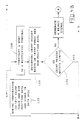
- a test for completion of the job is initiated. If no further terminations are needed, an end-of-job signal is generated and the machine is shut down. Otherwise, a wire is terminated in a respective terminal.
- force and ram position data elements are collected and recorded for different incremental values.
- the crimp height of the present termination is determined and compared with the desired crimp height. If an out of tolerance condition exists, a reject signal is generated, the machine again is automatically adjusted, and if the job is not yet complete, another wire is terminated in a respective terminal as above. If an out of tolerance condition does not exist, an accept signal is generated and a comparison is made between the desired crimp height and the crimp height of several of the most recent terminations to determine whether or not there is a trend toward an out-of-tolerance condition. If there is such a trend, the machine is again automatically adjusted and production resumed.
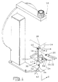
- a crimping press 10 having a base 12 and a ram 14 arranged for reciprocating opposed motion relative to the base 12.
- the crimping press 10 in the present example, is the type having a flywheel and clutch arrangement for imparting the reciprocating motion to the ram 14; however, other types of presses having a suitable ram stroke may be used in the practice of the present invention.
- the base 12 and ram 14 each carry a mating half of a crimping die set in the usual manner.
- the die set includes an anvil 16 which is removably attached to a base plate 17 and a punch 18 which is removably attached to the ram 14, as shown in Figure 1.
- the base plate 17 is coupled to the base 12 in a manner that will be described below.
- a typical terminal 20 is shown, in Figure 1, crimped onto a pair of wire leads 22.
- a strain gage 24 is attached to the anvil 16 in the usual manner by epoxy or soldering.
- a pair of leads 26 carry a signal that is proportional to the stress placed on the anvil 16 which is transferred from the ram 14, through the terminal 20 and wires 22 being crimped, to the anvil 16.
- the signal appearing on the leads 26 is indicative of the force imposed upon the terminal 20 during crimping, as set forth in more detail in the aforementioned EP-A-0 367 521.
- a linear distance sensor 30 is arranged to measure displacement of the ram 14 with respect to the base 12.
- the sensor 30 includes a stator 32, which is rigidly attached to the base 12 by a suitable bracket 34, and an armature which is movable within the stator in the vertical direction as viewed in Figure 1.
- a push rod 36 projects upwardly from the stator 32 and has one end attached to the movable armature and the other end adjustably attached to the ram 14 by means of a suitable bracket 38 and adjusting nut 40.
- a pair of leads 42 carry a signal that is proportional to the vertical position of the armature within the stator. This signal is indicative of the vertical distance between the anvil 16 and the punch 18 as set forth in more detail in the EP-A-0 367 521.
- the actual crimp height of the crimped terminal 20 can be accurately determined. Additionally, other parameters may be determined as well, such as peak force exerted on the terminal 20 and the amount of work performed to complete the crimp.
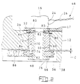
- Figure 2 shows how the base plate 17 is coupled to the base 12, by means of an adjustable platen or coupling means 48.
- the base 12 has a threaded bore 50 formed therethrough having an axis that is substantially parallel with the axis of movement of the ram 14.
- a counterbore 52 is formed in the top surface 54 concentric with the threaded bore 50 and an elongated recess 56 is formed in the bottom surface 58 of the base 12.
- a threaded sleeve 60 is in mating engagement with the threaded bore 50 and has parallel opposing ends 62 and 64.
- the pitch of the threads is relatively fine so that sufficiently accurate adjustments may be made. Additionally, the thread must be massive enough to support the loads imposed by the terminating operation.
- a sprocket wheel 66 is pinned to the end 62 of the threaded sleeve 60 by means of two or more pins 68, the sprocket being concentric with the threaded bore 50. Note that the pins 68 do not hold the two parts together axially, but rather provide rotational coupling.
- a sleeve 70 having an outer diameter 72 is disposed within a bore 74 formed axially through the sprocket 66 and threaded sleeve 60 and concentric thereto. The outer diameter 72 is sized for a slip fit with the bore 74.
- a hub or flange 76 is attached to one end of the sleeve 70 and abuts the undersurface of the sprocket 66, as best seen in Figure 2.
- An adapter collar 80 having a central bore which engages the outer diameter 72 of the sleeve 70 is pinned to the sleeve 70 by means of the pins 82 as shown in Figure 2.
- the base plate 17 is attached to the adapter collar 80 by means of the screw fasteners 83.
- the collar 80 is positioned on the sleeve 70 so that the threaded sleeve 60 and sprocket wheel 66 are held captive between the flange 76 and collar 80 with a slight amount of axial play.
- the pinned assembly of the threaded sleeve 60 and the sprocket 66 is free to rotate on the sleeve 70 within the limits set by the amount of clearance indicated as "C" in Figure 2. That is, as the sprocket wheel 66 is caused to rotate in one direction, the threaded sleeve 60 will move upwardly in the threaded bore 50, as viewed in Figure 2, until the side of the sprocket 66 engages the inner surface 84 of the recess 56. As the sprocket wheel 66 is caused to rotate in the opposite direction, the threaded sleeve 60 will move downwardly in the threaded bore 50 until the base plate 17 engages the top surface 54 of the base 12.
- a timing belt or chain 86 in driving engagement with the sprocket wheel 66 extends within the recess 56 to a stepper motor, not shown.
- the stepper motor as will be described below, is arranged to drive the timing belt 86 a precise amount in a given direction to raise or lower the base plate 17 a desired amount.
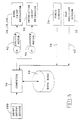
- wire crimping mechanism is identified as 16, 18, and 48 which represent the anvil, punch, and coupling means respectively
- force and ram position sensors are identified as 24 and 30 which represent the strain gage and linear distance sensor respectively.
- An insulation crimping mechanism 90 is depicted in Figure 3 as an example of other instrumentalities that may be controlled in a manner similar to that of the wire crimping mechanism. Other similar instrumentalities may also be controlled in a similar way.
- the actual adjusting means which physically moves or adjusts the coupling means 48, in the case of the wire crimp mechanism, or another adjustable device in the case of the insulation crimp mechanism, are driven by stepper motors 92 and 94 respectively.
- a computer 96 having a storage device 98 associated therewith for storing a data base and an input/output device 100 for operator communication, is arranged to drive the stepper motors 92 and 94. This is done in response to operator input through the device 100 and input from either the force sensor 24 or the ram position sensor 30.
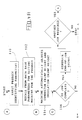
- the operation of the machine 10 will now be described in detail with reference to the logic diagram of Figure 4. It is assumed that a data base containing appropriate product information has already been created and stored on the storage device 98 in a manner that is well known in the art.
- the data base would include such product identifying parameters as terminal part number and crimp height, wire gage, number of wires, and applicator or tooling part number.
- the operator determines which product is to be crimped and inputs into the device 100 the product identifying code or number as well as wire type, wire size, and number of conductors, shown as step 110 in Figure 4.
- the computer 96 by means of a stored program, recalls from the data base, parameters for setting various elements of the machine, including crimp height, based upon the parameters which were input by the operator, shown as step 112.
- the computer 96 automatically adjusts the wire crimp mechanism 48 and the insulation crimp mechanism 90 by driving the stepper motors 92 and 94 respectively until the desired nominal crimp height of each is obtained shown as step 114.
- step 116 the computer 96 interrogates an end-of-job switch which may have been previously set by the operator. If set, an end-of-job signal is generated and displayed to the operator on the input/output device 100. If another job is required, control is passed to the point indicated as A to repeat the steps 110 through 116.
- the computer 96 enables the press drive motor, not shown, to drive the ram 14 through an operating cycle, thereby completing a termination, step 118.
- the computer 96 monitors the force and ram position sensors and records on the storage device 98 a series of data element pairs each of which is indicative of an amount of force on the terminal 20 and a corresponding position of the ram 14 as indicated by the sensors 24 and 30. See step 120 of Figure 4.
- any number of data element pairs may be collected and stored in this manner for a given resolution; however, practical considerations have shown that a data sampling rate of about 4000 pairs per second provides sufficient resolution to obtain a desired crimp height within a range of about plus or minus 0,025 mm (0.001 inches).
- the crimp height is determined, see step 122, based on the crimp force and ram position data in accordance with the teachings of the aforementioned EP-A-0367 521.
- the computer 96 compares the determined crimp height with the allowable range of crimp heights in step 124.
- a reject signal is generated and displayed on the input/output device 100 so that the operator can discard the defective termination.
- the reject signal could actuate a mechanism to rout the defective termination to a preselected location for later disposal. Control is then passed to the point indicated as B and steps 114 through 124 are repeated.
- step 126 recalls the most recent data element pairs.
- the data element pairs are then analyzed by the computer 96 by any suitable method to determine whether or not there is an out-of-tolerance trend, that is, in a relatively few number of additional operating cycles of the machine 10, the determined crimp height will be outside of the allowable range. If such a trend does exist, control is passed to the point indicated as B and steps 114 through 126 are repeated, otherwise control is passed to the point indicated as C thereby bypassing step 114.
- Step 114 is constructed so that the machine 10 will automatically adjust the appropriate mechanisms both initially, based on the manually input parameters and ongoing, based on the results of steps 124 and 126. This can easily be done by software within the computer 96 in a variety of ways that are well-known in the industry.
- Steps 114 and 124 of Figure 4 can be further enhanced by providing a mechanism to shut down the machine 10 in the event that an attempted automatic adjustment fails to bring the termination within the allowable limits. In such case an appropriate message can be displayed on the device 100 soliciting operator action.
- An important advantage of the present invention is a wire terminating machine having the capability to monitor the quality of the termination by performing quantitative tests and then to adjust appropriate mechanisms of the machine to maintain that quality within acceptable preselected limits.
- the quantitative testing and adjusting occur automatically during production, requiring no operator intervention and thereby significantly reducing machine down time and reducing out of tolerance terminations.
Claims (9)
- Verfahren zum Anschließen einer Vielzahl von Drähten (22) in einer Vielzahl von Anschlüssen (20) mittels einer automatisierten Maschine (10) mit einem Sockel (12), einem Preßkolben (14), der eingerichtet ist für eine bezüglich des Sockels (12) hin- und hergehende Bewegung, und mit einem Werkzeugsatz (16, 18) mit einem Amboß (16) und einem dazu passenden Stempel (18) zum Durchführen des Anschließens von wenigstens einem der Drähte (22) in einem Anschluß (20), wobei der Amboß (16) mit dem Sockel (12) und der Stempel (18) mit dem Preßkolben (14) gekoppelt ist, mit den Schritten: Bestimmen und Aufzeichnen der auf den Werkzeugsatz (16, 18) durch den Preßkolben (14) beim Anschließen ausgeübten Kraft; Bestimmen und Aufzeichnen der Position des Preßkolbens (14) in bezug auf den Sockel (12) während der hin- und hergehenden Bewegung; Bestimmen des Wertes der Klemmenhöhe bei der Anschließung auf der Basis der festgelegten Preßkolbenposition und der korrespondierenden Kraft, und Vergleichen des bestimmten Wertes mit einem gewünschten Wert, und bei einem ungünstigen Vergleich Erzeugen eines Einstellsignales; und Einstellen der Höhe des Ambosses (16) über dem Sockel (12) in Reaktion auf das Einstellsignal, wobei das Verfahren außerdem die Schritte aufweist:(a) Eingeben einer eine gewünschte Klemmenhöhe (110) bezeichnenden Kodierung;(b) Automatisches Einstellen der Höhe des Ambosses über dem Sockel in Reaktion auf das Eingeben von Schritt (a) oder auf das Vergleichen von Schritt (f)(i) (112, 114);(c) Prüfen der Vollendung der Arbeit (116);(i) Erzeugen eines Ende-der-Arbeit-Signales und Beenden des Betriebes der Maschine, wenn keine weiteren Anschließungen benötigt werden;(ii) im anderen Fall Antreiben der Maschine zum Durchführen eines Anschließens von einem aus der Vielzahl der Drähte an einem entsprechenden Anschluß (118);(d) während des Anschließens des Schrittes (c) (ii) Bestimmen und Aufzeichnen einer dem Werkzeugsatz erteilten Kraft und gleichzeitig einer korrespondierenden Preßkolbenposition für unterschiedliche Inkrementalwerte entweder der Kraft oder der Preßkolbenposition (120);(e)Bestimmen des Wertes der Klemmenhöhe bei der Anschließung (120);(f) Vergleichen des bestimmten Wertes der Klemmenhöhe mit dem Wert der gewünschten Klemmenhöhe (124),(i) wenn die Klemmenhöhe außerhalb einer Toleranz liegt, erzeuge ein Ausschußsignal und gehe zu Schritt (b);(ii) im anderen Fall erzeuge ein Annahmesignal; und(g) gehe zu Schritt (c).
- Verfahren nach Anspruch 1, mit einem Schritt (f) (i) vor dem Schritt (g), wie folgt:(f)(i) Vergleichen einer sehr neuen Serie der bestimmten Werte der Klemmenhöhe mit dem Wert der gewünschten Klemmenhöhe und, wenn der Vergleich einen Trend zu einer Bedingung außerhalb der Toleranz aufzeigt, gehe zu Schritt (b) (126);
und wobei das Einstellen von Schritt (b) zusätzlich stattfindet in Reaktion auf die Bedingung außerhalb der Toleranz von Schritt (f)(i). - Verfahren nach Anspruch 1 oder 2, wobei das Bestimmen und Aufzeichnen der Kraft und der Preßkolbenposition für verschiedene Inkrementalwerte nur der Preßkolbenposition stattfindet.
- Verfahren nach Anspruch 1, 2 oder 3, wobei das Vergleichen von Schritt (f)(i) das Erzeugen eines Einstellsignals aufweist, das kennzeichnend ist für die Größe der außerhalb der Toleranz liegenden Klemmenhöhe und wobei das automatische Einstellen von Schritt (b) in Proportionalreaktion auf das Einstellsignal stattfindet.
- Automatisierte Maschine (10) zum Anschließen einer Vielzahl von Drähten (22) in einer Vielzahl von Anschlüssen (22), mit einem Sockel (12), einem Preßkolben (14), der für eine hin- und hergehende Bewegung in bezug auf den Sockel (12) eingerichtet ist und mit einem Werkzeugsatz (16, 18) mit einem Amboß (16) und einem dazu passenden Stempel (18) zum Durchführen des Anschließens von wenigstens einem der Drähte (22) in einem Anschluß (20), wobei der Amboß (16) mit dem Sockel (12) und der Stempel (18) mit dem Preßkolben (14) gekoppelt ist, wobei die Maschine aufweist:(a) Einrichtungen (24, 26, 96, 98) zum Bestimmen und Aufzeichnen der auf den Werkzeugsatz (16, 18) von dem Preßkolben (14) während des Anschließens aufgebrachten Kraft;(b) Einrichtungen (30, 42, 96, 98) zum Bestimmen und Aufzeichnen der Position des Preßkolbens (14) in bezug auf den Sockel (12) während der Hin- und Herbewegung;(c) Einrichtungen (96, 98) zum Bestimmen des Wertes der Klemmenhöhe beim Anschließen auf der Basis der bestimmten Preßkolbenposition und der korrespondierenden Kraft für eine Vielzahl von verschiedenen Inkrementalwerten, entweder der Kraft oder der Preßkolbenposition;(d) Einrichtungen (96, 98) zum Vergleichen des bestimmten Wertes der Klemmenhöhe mit einem dafür gewünschten Wert, und wenn das Ergebnis des Vergleichs in einer Höhe liegt, die einen vorbestimmten Wert überschreitet, wird ein Einstellsignal erzeugt; und(e) an dem Sockel (12) angebrachte Koppeleinrichtungen (48) zum Tragen des Ambosses (16) in einem Abstand über dem Sockel (12) in Richtung zum Preßkolben (14), wobei die Koppeleinrichtungen (48) auf das Einstellsignal zum Verändern der Klemmenhöhe einer nachfolgend gebildeten Anschließung reagieren.
- Automatisierte Maschine (10) nach Anspruch 5, wobei die Einrichtung (96, 98) zum Bestimmen des Wertes der Klemmenhöhe einen Computer (96) aufweist, und wobei die Einrichtung (96, 98) zum Aufzeichnen der Kraft und der Preßkolbenposition eine Datenbank (98), die von dem Computer (96) erzeugt worden ist, aufweist, und die die aufgezeichnete Kraft und die Preßkolbenposition für eine Vielzahl von Anschließungen enthält; wobei die Maschine ferner Einrichtungen zum Vergleichen der bestimmten Werte der Klemmenhöhe einer Vielzahl von Anschließungen mit dem Wert der gewünschten Klemmenhöhe aufweist, um zu bestimmen, ob die Werte einen Trend in Richtung auf eine Bedingung außerhalb der Toleranz kennzeichnen oder nicht, und um, wenn eine derartige Kennzeichnung vorliegt, ein Einstellsignal zu erzeugen.
- Automatisierte Maschine (10) nach Anspruch 5 oder 6, wobei die Koppeleinrichtung (48) aufweist:(a) eine den Amboß (16) tragende Grundplatte (17), die mit dem Sockel (12) gekoppelt ist und eingerichtet ist, eine Bewegung in Richtung zu dem Preßkolben (14) hin und weg von dem Sockel (12) und in einer entgegengesetzten Richtung weg von dem Preßkolben (14) und zu dem Sockel (12) hin zu vollführen;(b) Schraubenmittel (50, 60) zum Erteilen der Bewegung auf die Sockelplatte durch Rotation der Schraubenmittel; und(c) ein rotierendes Stellglied (66, 86, 92), das auf das Einstellsignal zum Drehen der Schraubenmittel (50, 60) um einen gewünschten Winkelbetrag in einer gewünschten Richtung reagiert.
- Automatisierte Maschine (10) nach Anspruch 7, wobei das Schraubenmittel (50, 60) der Koppeleinrichtung (48) eine relativ feine Stellschraube (60) in einer Gewindeverbindung mit einer Gewindebohrung (50) in dem Sockel ist, wobei die Gewindebohrung (50) eine Achse hat, die im wesentlichen parallel mit der Achse der Hin- und Herbewegung des Preßkolbens (14) ist.
- Automatisierte Maschine (10) nach Anspruch 8, wobei das drehbare Stellglied ein Motor (92) ist, der antriebsmäßig mit der Schraube (60) mittels eines mit Zähnen versehenen Rades (66) und eines Steuerriemens (86) gekoppelt ist.
Applications Claiming Priority (2)
| Application Number | Priority Date | Filing Date | Title |
|---|---|---|---|
| US07/351,108 US4916810A (en) | 1989-05-12 | 1989-05-12 | Method and apparatus for terminating wires to terminals |
| US351108 | 1989-05-12 |
Publications (3)
| Publication Number | Publication Date |
|---|---|
| EP0397434A2 EP0397434A2 (de) | 1990-11-14 |
| EP0397434A3 EP0397434A3 (de) | 1991-04-24 |
| EP0397434B1 true EP0397434B1 (de) | 1994-12-21 |
Family
ID=23379605
Family Applications (1)
| Application Number | Title | Priority Date | Filing Date |
|---|---|---|---|
| EP90304915A Expired - Lifetime EP0397434B1 (de) | 1989-05-12 | 1990-05-04 | Verfahren und Vorrichtung zur Verbindung eines Drahtes an einer Anschlussklemme |
Country Status (8)
| Country | Link |
|---|---|
| US (1) | US4916810A (de) |
| EP (1) | EP0397434B1 (de) |
| JP (1) | JP2764221B2 (de) |
| KR (1) | KR900019298A (de) |
| DE (1) | DE69015251T2 (de) |
| ES (1) | ES2065487T3 (de) |
| MX (1) | MX171280B (de) |
| NO (1) | NO176340C (de) |
Families Citing this family (41)
| Publication number | Priority date | Publication date | Assignee | Title |
|---|---|---|---|---|
| US5271254A (en) * | 1989-12-05 | 1993-12-21 | The Whitaker Corporation | Crimped connector quality control method apparatus |
| US5197186A (en) * | 1990-05-29 | 1993-03-30 | Amp Incorporated | Method of determining the quality of a crimped electrical connection |
| US5275032A (en) * | 1990-05-30 | 1994-01-04 | The Whitaker Corporation | Method and apparatus for controlling the crimp height of crimped electrical connections |
| GB9012058D0 (en) * | 1990-05-30 | 1990-07-18 | Amp Gmbh | Method of,and apparatus for,controlling the crimp height of crimped electrical connections |
| US5195042A (en) * | 1990-06-27 | 1993-03-16 | Burndy Corporation | Apparatus and method for controlling crimping of articles |
| US5084960A (en) * | 1991-01-24 | 1992-02-04 | Amp Incorporated | Apparatus for terminating wires to terminals |
| US5101651A (en) * | 1991-02-22 | 1992-04-07 | Amp Incorporated | Apparatus for determining the force imposed on a terminal during crimping thereof |
| US5123165A (en) * | 1991-03-21 | 1992-06-23 | Amp Incorporated | Method of determining the crimp height of a crimped electrical connection |
| JP2588936Y2 (ja) * | 1991-07-09 | 1999-01-20 | 新明和工業株式会社 | 電線処理設備 |
| JPH0529056A (ja) * | 1991-07-18 | 1993-02-05 | Nippon Autom Mach Kk | 端子圧着自動調整装置 |
| US5491994A (en) * | 1991-12-11 | 1996-02-20 | Diamond Die & Mold Company | Crimp height monitor |
| JP3042195B2 (ja) * | 1992-09-01 | 2000-05-15 | 住友電気工業株式会社 | 圧着端子の加工方法及びその装置 |
| US5228326A (en) * | 1993-02-09 | 1993-07-20 | The Whitaker Corporation | Crimp height adjustment mechanism |
| US5727409A (en) * | 1994-12-28 | 1998-03-17 | Yazaki Corporation | Method of controlling a terminal crimping apparatus |
| US5937505A (en) * | 1995-03-02 | 1999-08-17 | The Whitaker Corporation | Method of evaluating a crimped electrical connection |
| US5701487A (en) * | 1995-03-27 | 1997-12-23 | Sun Microsystems, Inc. | Method and apparatus for displaying locations of errors detected inside software macro calls |
| US5829289A (en) * | 1995-06-05 | 1998-11-03 | Ford Motor Company | Method of controlling a crimp press for crimping an assembly |
| US5651282A (en) * | 1995-06-05 | 1997-07-29 | Ford Motor Company | Method of controlling a crimp press for crimping a hose assembly |
| JPH103978A (ja) * | 1996-06-12 | 1998-01-06 | Yazaki Corp | 端子圧着装置の制御方法 |
| DE19540709C1 (de) * | 1995-11-02 | 1997-01-09 | Freudenberg Carl Fa | Vorrichtung zur Herstellung einer Quetschverbindung zwischen einem plastisch verformbaren, metallischen Polschuh und einem Kabelende |
| JPH09330779A (ja) * | 1996-06-12 | 1997-12-22 | Yazaki Corp | 端子圧着装置の制御方法 |
| EP0878878B1 (de) * | 1997-05-12 | 2005-01-12 | Steinel AG | Aufnahmeadapter zur Kraftmessung |
| DE19738298C1 (de) * | 1997-09-02 | 1999-04-08 | Poly Clip System Gmbh & Co Kg | Verfahren zum Einrichten einer Verschließmaschine und Vorrichtung zum Verschließen von Verschlußklammern |
| GB9901641D0 (en) * | 1999-01-26 | 1999-03-17 | Raychem Ltd | Crimping composite electrical insulators |
| US6487885B2 (en) * | 2000-10-30 | 2002-12-03 | Komax Holding Ag | Method and apparatus for producing a crimped connection |
| US6845645B2 (en) * | 2001-04-06 | 2005-01-25 | Michael A. Bartrom | Swaging feedback control method and apparatus |
| DE10232470A1 (de) * | 2002-07-17 | 2004-02-05 | Bernhard Schäfer Werkzeug- und Sondermaschinenbau GmbH | Verfahren und Vorrichtung zur Qualitätssicherung von Crimpverbindungen |
| JP4436053B2 (ja) * | 2003-02-13 | 2010-03-24 | 矢崎総業株式会社 | 圧着端子の圧着状況推定装置と圧着端子の良否判定装置 |
| DE10316187B3 (de) * | 2003-04-09 | 2004-10-21 | Bernhard Schäfer Werkzeug- und Sondermaschinenbau GmbH | Reinigungseinrichtung für eine Vorrichtung zum Ancrimben eines Crimps an eine Kabalende |
| WO2004109461A2 (en) * | 2003-06-04 | 2004-12-16 | Zusi Christopher J | Automated machine setup with modular tooling |
| DE102005025173C5 (de) * | 2005-06-01 | 2013-08-22 | Poly-Clip System Gmbh & Co Kg | Clipmaschine mit einem Verschließhebel |
| CN100372195C (zh) * | 2005-07-13 | 2008-02-27 | 南京埃斯顿数字技术有限公司 | 通用端子压着机压力监控系统 |
| JP4898463B2 (ja) | 2007-01-16 | 2012-03-14 | 矢崎総業株式会社 | 端子圧着装置及び端子圧着方法 |
| JP5883735B2 (ja) * | 2012-07-12 | 2016-03-15 | 矢崎総業株式会社 | 圧着端子のクリンプハイト測定方法及びその装置、クリンプハイト管理方法及びその装置 |
| US9362700B2 (en) | 2013-08-13 | 2016-06-07 | Tyco Electronics Corporation | Device for determining a crimp height of a crimped electrical connection |
| CN105204464A (zh) * | 2015-09-18 | 2015-12-30 | 深圳市志海和科技有限公司 | 一种线束压着品质在线管理系统和方法 |
| US10522960B2 (en) | 2017-05-03 | 2019-12-31 | Te Connectivity Corporation | Crimp quality monitoring method and system for use with a hydraulic crimping apparatus |
| CA3090253C (en) | 2018-01-31 | 2023-02-21 | Abb Schweiz Ag | Crimping tool with wireless communication system |
| CN109519610B (zh) * | 2018-11-22 | 2020-12-22 | 扬州锻压机床有限公司 | 一种高度可调节装置及其安装方法 |
| DE102019101017A1 (de) * | 2019-01-16 | 2020-07-16 | Harting Electric Gmbh & Co. Kg | Verfahren und Vorrichtung zur Überwachung des Zustands einer Crimpeinrichtung |
| CN114102107B (zh) * | 2021-12-12 | 2022-09-30 | 安费诺汽车连接系统(常州)有限公司 | 汽车电源端子自动生产设备 |
Family Cites Families (6)
| Publication number | Priority date | Publication date | Assignee | Title |
|---|---|---|---|---|
| US4400873A (en) * | 1979-10-18 | 1983-08-30 | General Electric Company | Apparatus for use in making electrical interconnections |
| JPS6031092U (ja) * | 1983-08-09 | 1985-03-02 | シ−ケ−デイ株式会社 | 端子圧着機 |
| EP0184204A1 (de) * | 1984-12-06 | 1986-06-11 | Siemens Aktiengesellschaft | Kraftregelung für Crimpmaschinen |
| JPS61185878A (ja) * | 1985-02-12 | 1986-08-19 | 住友電装株式会社 | 電線への端子圧着方法 |
| US4914602A (en) * | 1987-05-13 | 1990-04-03 | Furukawa Electric Co., Ltd. | Method for detecting the molding defectiveness of a press-molded workpiece and a terminal press-bonding apparatus utilizing the same |
| US4856186A (en) * | 1988-11-04 | 1989-08-15 | Amp Incorporated | Apparatus and method for determination of crimp height |
-
1989
- 1989-05-12 US US07/351,108 patent/US4916810A/en not_active Expired - Lifetime
-
1990
- 1990-05-04 DE DE69015251T patent/DE69015251T2/de not_active Expired - Fee Related
- 1990-05-04 ES ES90304915T patent/ES2065487T3/es not_active Expired - Lifetime
- 1990-05-04 EP EP90304915A patent/EP0397434B1/de not_active Expired - Lifetime
- 1990-05-08 MX MX020629A patent/MX171280B/es unknown
- 1990-05-10 KR KR1019900006588A patent/KR900019298A/ko active IP Right Grant
- 1990-05-11 NO NO902098A patent/NO176340C/no unknown
- 1990-05-14 JP JP2123964A patent/JP2764221B2/ja not_active Expired - Lifetime
Also Published As
| Publication number | Publication date |
|---|---|
| NO902098L (no) | 1990-11-13 |
| NO176340B (no) | 1994-12-05 |
| EP0397434A3 (de) | 1991-04-24 |
| DE69015251T2 (de) | 1995-07-13 |
| KR900019298A (ko) | 1990-12-24 |
| JP2764221B2 (ja) | 1998-06-11 |
| EP0397434A2 (de) | 1990-11-14 |
| NO902098D0 (no) | 1990-05-11 |
| MX171280B (es) | 1993-10-15 |
| NO176340C (no) | 1995-03-15 |
| JPH0315182A (ja) | 1991-01-23 |
| ES2065487T3 (es) | 1995-02-16 |
| US4916810A (en) | 1990-04-17 |
| DE69015251D1 (de) | 1995-02-02 |
Similar Documents
| Publication | Publication Date | Title |
|---|---|---|
| EP0397434B1 (de) | Verfahren und Vorrichtung zur Verbindung eines Drahtes an einer Anschlussklemme | |
| EP0460441B1 (de) | Verfahren zur Qualitätsbestimmung einer Quetschverbindung | |
| JP2686663B2 (ja) | 端子圧着高さ測定方法および装置 | |
| EP0459476B1 (de) | Verfahren und Vorrichtung für die Einstellung der Crimphöhe einer gequetschten elektrischen Verbindung | |
| US5937505A (en) | Method of evaluating a crimped electrical connection | |
| US5092026A (en) | Crimp height monitor | |
| US5123165A (en) | Method of determining the crimp height of a crimped electrical connection | |
| US6212924B1 (en) | Process and apparatus for determination of the quality of a crimped connection | |
| US5727409A (en) | Method of controlling a terminal crimping apparatus | |
| US5697146A (en) | Apparatus for crimping terminal to electrical wire | |
| CN103250309A (zh) | 具有压接质量监测系统的压接设备 | |
| US5275032A (en) | Method and apparatus for controlling the crimp height of crimped electrical connections | |
| EP1211761B1 (de) | Verfahren und Einrichtung zur Bestimmung der Qualität einer Crimpverbindung | |
| US20060198915A1 (en) | Method and device for quality assurance of crimp joints | |
| US5122975A (en) | Methods and apparatus for marking and identifying hooks of electric motors | |
| EP0419129B1 (de) | Kontrollsystem der Crimpenhöhe | |
| EP0491259A1 (de) | Vorrichtung zur Überwachung von Spannkräften in Drehfuttern | |
| DE102017107972B4 (de) | Verfahren zum Betreiben eines Oberflächenmessgerätes | |
| CN113365806B (zh) | 用于监控压接装置的压紧元件的状态的方法和设备 | |
| EP0699490B1 (de) | Überprüfungsvorrichtung, insbesondere für Verformungsmaschinen | |
| US5241486A (en) | Methods and apparatus for marking and identifying hooks of electric motors | |
| MXPA00007162A (en) | Terminal crimping quality decision method/device and frictional wear state detection method of crimping die | |
| JPS62259216A (ja) | Vtr磁気ヘツド位置調整装置 |
Legal Events
| Date | Code | Title | Description |
|---|---|---|---|
| PUAI | Public reference made under article 153(3) epc to a published international application that has entered the european phase |
Free format text: ORIGINAL CODE: 0009012 |
|
| AK | Designated contracting states |
Kind code of ref document: A2 Designated state(s): CH DE ES FR GB IT LI NL |
|
| 17P | Request for examination filed |
Effective date: 19901227 |
|
| PUAL | Search report despatched |
Free format text: ORIGINAL CODE: 0009013 |
|
| AK | Designated contracting states |
Kind code of ref document: A3 Designated state(s): CH DE ES FR GB IT LI NL |
|
| RAP1 | Party data changed (applicant data changed or rights of an application transferred) |
Owner name: THE WHITAKER CORPORATION |
|
| 17Q | First examination report despatched |
Effective date: 19940126 |
|
| GRAA | (expected) grant |
Free format text: ORIGINAL CODE: 0009210 |
|
| AK | Designated contracting states |
Kind code of ref document: B1 Designated state(s): CH DE ES FR GB IT LI NL |
|
| REF | Corresponds to: |
Ref document number: 69015251 Country of ref document: DE Date of ref document: 19950202 |
|
| ITF | It: translation for a ep patent filed |
Owner name: PROROGA CONCESSA IN DATA: 07.04.95;GUZZI E RAVIZZ |
|
| REG | Reference to a national code |
Ref country code: ES Ref legal event code: FG2A Ref document number: 2065487 Country of ref document: ES Kind code of ref document: T3 |
|
| ET | Fr: translation filed | ||
| PLBE | No opposition filed within time limit |
Free format text: ORIGINAL CODE: 0009261 |
|
| STAA | Information on the status of an ep patent application or granted ep patent |
Free format text: STATUS: NO OPPOSITION FILED WITHIN TIME LIMIT |
|
| 26N | No opposition filed | ||
| PGFP | Annual fee paid to national office [announced via postgrant information from national office to epo] |
Ref country code: NL Payment date: 19990322 Year of fee payment: 10 |
|
| PGFP | Annual fee paid to national office [announced via postgrant information from national office to epo] |
Ref country code: GB Payment date: 19990406 Year of fee payment: 10 |
|
| PGFP | Annual fee paid to national office [announced via postgrant information from national office to epo] |
Ref country code: FR Payment date: 19990504 Year of fee payment: 10 |
|
| PGFP | Annual fee paid to national office [announced via postgrant information from national office to epo] |
Ref country code: ES Payment date: 19990514 Year of fee payment: 10 |
|
| PG25 | Lapsed in a contracting state [announced via postgrant information from national office to epo] |
Ref country code: GB Free format text: LAPSE BECAUSE OF NON-PAYMENT OF DUE FEES Effective date: 20000504 |
|
| PG25 | Lapsed in a contracting state [announced via postgrant information from national office to epo] |
Ref country code: ES Free format text: THE PATENT HAS BEEN ANNULLED BY A DECISION OF A NATIONAL AUTHORITY Effective date: 20000505 |
|
| PG25 | Lapsed in a contracting state [announced via postgrant information from national office to epo] |
Ref country code: NL Free format text: LAPSE BECAUSE OF NON-PAYMENT OF DUE FEES Effective date: 20001201 |
|
| GBPC | Gb: european patent ceased through non-payment of renewal fee |
Effective date: 20000504 |
|
| PG25 | Lapsed in a contracting state [announced via postgrant information from national office to epo] |
Ref country code: FR Free format text: LAPSE BECAUSE OF NON-PAYMENT OF DUE FEES Effective date: 20010131 |
|
| NLV4 | Nl: lapsed or anulled due to non-payment of the annual fee |
Effective date: 20001201 |
|
| REG | Reference to a national code |
Ref country code: FR Ref legal event code: ST |
|
| PGFP | Annual fee paid to national office [announced via postgrant information from national office to epo] |
Ref country code: DE Payment date: 20010530 Year of fee payment: 12 |
|
| PGFP | Annual fee paid to national office [announced via postgrant information from national office to epo] |
Ref country code: CH Payment date: 20010627 Year of fee payment: 12 |
|
| REG | Reference to a national code |
Ref country code: ES Ref legal event code: FD2A Effective date: 20020304 |
|
| PG25 | Lapsed in a contracting state [announced via postgrant information from national office to epo] |
Ref country code: LI Free format text: LAPSE BECAUSE OF NON-PAYMENT OF DUE FEES Effective date: 20020531 Ref country code: CH Free format text: LAPSE BECAUSE OF NON-PAYMENT OF DUE FEES Effective date: 20020531 |
|
| PG25 | Lapsed in a contracting state [announced via postgrant information from national office to epo] |
Ref country code: DE Free format text: LAPSE BECAUSE OF NON-PAYMENT OF DUE FEES Effective date: 20021203 |
|
| REG | Reference to a national code |
Ref country code: CH Ref legal event code: PL |
|
| PG25 | Lapsed in a contracting state [announced via postgrant information from national office to epo] |
Ref country code: IT Free format text: LAPSE BECAUSE OF NON-PAYMENT OF DUE FEES;WARNING: LAPSES OF ITALIAN PATENTS WITH EFFECTIVE DATE BEFORE 2007 MAY HAVE OCCURRED AT ANY TIME BEFORE 2007. THE CORRECT EFFECTIVE DATE MAY BE DIFFERENT FROM THE ONE RECORDED. Effective date: 20050504 |