EP0395778B1 - Vorrichtung mit implantierbarer Infusionskammer und einem sich von dieser forterstreckenden Katheter - Google Patents
Vorrichtung mit implantierbarer Infusionskammer und einem sich von dieser forterstreckenden Katheter Download PDFInfo
- Publication number
- EP0395778B1 EP0395778B1 EP19890108034 EP89108034A EP0395778B1 EP 0395778 B1 EP0395778 B1 EP 0395778B1 EP 19890108034 EP19890108034 EP 19890108034 EP 89108034 A EP89108034 A EP 89108034A EP 0395778 B1 EP0395778 B1 EP 0395778B1
- Authority
- EP
- European Patent Office
- Prior art keywords
- infusion chamber
- chamber
- puncture
- catheter
- infusion
- Prior art date
- Legal status (The legal status is an assumption and is not a legal conclusion. Google has not performed a legal analysis and makes no representation as to the accuracy of the status listed.)
- Expired - Lifetime
Links
- 238000001802 infusion Methods 0.000 claims description 93
- 238000002513 implantation Methods 0.000 claims description 20
- 238000007920 subcutaneous administration Methods 0.000 claims description 15
- 238000004873 anchoring Methods 0.000 claims description 14
- 239000000463 material Substances 0.000 claims description 14
- 210000000577 adipose tissue Anatomy 0.000 claims description 12
- 229920001296 polysiloxane Polymers 0.000 claims description 12
- 210000001367 artery Anatomy 0.000 claims description 5
- 239000011324 bead Substances 0.000 claims description 5
- 210000004204 blood vessel Anatomy 0.000 claims description 3
- 238000010276 construction Methods 0.000 claims description 2
- 230000000149 penetrating effect Effects 0.000 claims 1
- 238000003780 insertion Methods 0.000 description 28
- 230000037431 insertion Effects 0.000 description 28
- 238000007789 sealing Methods 0.000 description 9
- 239000003814 drug Substances 0.000 description 7
- 206010028980 Neoplasm Diseases 0.000 description 6
- 229940079593 drug Drugs 0.000 description 6
- 230000002792 vascular Effects 0.000 description 6
- 238000011161 development Methods 0.000 description 5
- 239000007924 injection Substances 0.000 description 5
- 238000002347 injection Methods 0.000 description 5
- 239000012528 membrane Substances 0.000 description 3
- 230000006641 stabilisation Effects 0.000 description 3
- 238000011105 stabilization Methods 0.000 description 3
- 238000001361 intraarterial administration Methods 0.000 description 2
- 238000000034 method Methods 0.000 description 2
- 238000012986 modification Methods 0.000 description 2
- 230000004048 modification Effects 0.000 description 2
- 206010009944 Colon cancer Diseases 0.000 description 1
- 206010019695 Hepatic neoplasm Diseases 0.000 description 1
- 206010027476 Metastases Diseases 0.000 description 1
- 206010027457 Metastases to liver Diseases 0.000 description 1
- 208000007536 Thrombosis Diseases 0.000 description 1
- 238000002583 angiography Methods 0.000 description 1
- 239000002246 antineoplastic agent Substances 0.000 description 1
- 239000008280 blood Substances 0.000 description 1
- 210000004369 blood Anatomy 0.000 description 1
- 238000002512 chemotherapy Methods 0.000 description 1
- 229940127089 cytotoxic agent Drugs 0.000 description 1
- 238000013461 design Methods 0.000 description 1
- 238000012377 drug delivery Methods 0.000 description 1
- 230000000694 effects Effects 0.000 description 1
- 239000013013 elastic material Substances 0.000 description 1
- 239000003978 infusion fluid Substances 0.000 description 1
- 238000002350 laparotomy Methods 0.000 description 1
- 239000007788 liquid Substances 0.000 description 1
- 208000014018 liver neoplasm Diseases 0.000 description 1
- 238000002690 local anesthesia Methods 0.000 description 1
- 229940126601 medicinal product Drugs 0.000 description 1
- 210000000056 organ Anatomy 0.000 description 1
- 206010033675 panniculitis Diseases 0.000 description 1
- 230000002093 peripheral effect Effects 0.000 description 1
- 230000002787 reinforcement Effects 0.000 description 1
- 239000011343 solid material Substances 0.000 description 1
- 210000004304 subcutaneous tissue Anatomy 0.000 description 1
- 238000011477 surgical intervention Methods 0.000 description 1
- 238000001356 surgical procedure Methods 0.000 description 1
- 238000002560 therapeutic procedure Methods 0.000 description 1
- 210000001519 tissue Anatomy 0.000 description 1
- 238000012546 transfer Methods 0.000 description 1
- 230000005641 tunneling Effects 0.000 description 1
Images

Classifications
-
- A—HUMAN NECESSITIES
- A61—MEDICAL OR VETERINARY SCIENCE; HYGIENE
- A61M—DEVICES FOR INTRODUCING MEDIA INTO, OR ONTO, THE BODY; DEVICES FOR TRANSDUCING BODY MEDIA OR FOR TAKING MEDIA FROM THE BODY; DEVICES FOR PRODUCING OR ENDING SLEEP OR STUPOR
- A61M39/00—Tubes, tube connectors, tube couplings, valves, access sites or the like, specially adapted for medical use
- A61M39/02—Access sites
- A61M39/0208—Subcutaneous access sites for injecting or removing fluids
-
- A—HUMAN NECESSITIES
- A61—MEDICAL OR VETERINARY SCIENCE; HYGIENE
- A61M—DEVICES FOR INTRODUCING MEDIA INTO, OR ONTO, THE BODY; DEVICES FOR TRANSDUCING BODY MEDIA OR FOR TAKING MEDIA FROM THE BODY; DEVICES FOR PRODUCING OR ENDING SLEEP OR STUPOR
- A61M25/00—Catheters; Hollow probes
- A61M25/01—Introducing, guiding, advancing, emplacing or holding catheters
- A61M25/06—Body-piercing guide needles or the like
- A61M25/0662—Guide tubes
- A61M2025/0681—Systems with catheter and outer tubing, e.g. sheath, sleeve or guide tube
-
- A—HUMAN NECESSITIES
- A61—MEDICAL OR VETERINARY SCIENCE; HYGIENE
- A61M—DEVICES FOR INTRODUCING MEDIA INTO, OR ONTO, THE BODY; DEVICES FOR TRANSDUCING BODY MEDIA OR FOR TAKING MEDIA FROM THE BODY; DEVICES FOR PRODUCING OR ENDING SLEEP OR STUPOR
- A61M25/00—Catheters; Hollow probes
- A61M25/10—Balloon catheters
- A61M2025/1043—Balloon catheters with special features or adapted for special applications
- A61M2025/105—Balloon catheters with special features or adapted for special applications having a balloon suitable for drug delivery, e.g. by using holes for delivery, drug coating or membranes
-
- A—HUMAN NECESSITIES
- A61—MEDICAL OR VETERINARY SCIENCE; HYGIENE
- A61M—DEVICES FOR INTRODUCING MEDIA INTO, OR ONTO, THE BODY; DEVICES FOR TRANSDUCING BODY MEDIA OR FOR TAKING MEDIA FROM THE BODY; DEVICES FOR PRODUCING OR ENDING SLEEP OR STUPOR
- A61M39/00—Tubes, tube connectors, tube couplings, valves, access sites or the like, specially adapted for medical use
- A61M39/02—Access sites
- A61M39/0208—Subcutaneous access sites for injecting or removing fluids
- A61M2039/022—Subcutaneous access sites for injecting or removing fluids being accessible from all sides, e.g. due to a cylindrically-shaped septum
Definitions
- the invention relates to a device with an infusion chamber implantable in the subcutaneous fatty tissue of a patient, which has a region made of elastic material that can be pierced by means of an injection needle, and with an extension of the infusion chamber and into a blood vessel, such as an artery or a other body cavity insertable catheter.
- a subcutaneously implantable device for supplying liquid medicinal products which has an infusion chamber with a pierceable membrane as a puncture window and a hose connected to the chamber for the medication transfer.
- a perforation of the chamber rear wall preventing reinforcement is arranged opposite the puncture window.
- DE-PS 33 09 788 describes a similar device with an infusion chamber having a puncture puncture window and a catheter that can be connected to it.
- the infusion chamber has a peripheral bead which surrounds the puncture window and projects above it and on the underside thereof a plate protruding peripherally beyond the chamber and having perforations distributed around the circumference for fixation by means of threads in the implanted state.
- Devices of this type allow permanent venous or arterial vascular access.
- Devices intended for arterial vascular access differ from venous systems by a valve at the tip of the catheter in order to prevent occlusion by blood flowing back in the high-pressure arterial system due to thrombosis.
- Such devices used for selective injection of drugs used in vessels can be implanted subcutaneously, which in any case requires surgery under local anesthesia.
- the vessel into which a catheter is to be inserted is opened, for example by means of a puncture cannula or in another suitable manner, and the catheter is then introduced into the vessel. Then prepare an epifascial pocket for the infusion chamber and place the latter in the pocket so that a puncture window designed as a membrane lies outside the cut under the skin. After implantation and, if necessary, prior suction drainage, the wound must be closed with subcutaneous or skin sutures.
- a skin incision must be made in the area of this access and the catheter must be moved from a subcutaneous pocket for receiving the infusion chamber through a subcutaneous tunnel to the skin incision before the catheter can be inserted into the vessel.
- the subcutaneously implantable devices are particularly suitable for intra-arterial chemotherapy, which allows regional tumor therapy of primary tumors and metastases.
- an arteriography must be performed to know exactly to receive via the anatomical vascular supply of a tumor-bearing organ and thus to determine the location of the catheter tip in the vascular system for drug delivery.
- the advantage of the intra-arterial method is that higher concentrations of the chemotherapeutic agents to be used can be brought into the tumor tissue, thus allowing targeted treatment with fewer general side effects.
- the drug to be delivered intra-arterially can only be dispensed into the infusion chamber by puncturing the skin and the membrane of the puncture window and from there selectively into the tumor-supplying artery via the tube system inserted into the latter.
- the infusion chambers are surgically implanted intraoperatively and a further skin incision is made when the infusion chamber is positioned away from the vascular access, and the catheter must be moved through a subcutaneous tunnel to the skin incision before a catheter can be introduced into the vessel.
- a major operation is therefore always necessary, such as a laparotomy in the case of liver tumors, in order to insert the catheter exactly and to be able to place the infusion chamber.
- the burden associated with such an operation is often unreasonable for tumor patients, since, for example, liver metastases of a primary colon carcinoma have an average life expectancy of only about six months.
- the aim of the invention is to create a device of the aforementioned purpose, which is less invasive than the subcutaneously implantable systems and can therefore be implanted more easily and less stressfully for patients, but which also ensures a permanently effective seal of the puncture channels after puncturing for refilling .
- the design of the device according to the preamble of claim 1 as a system that can be implanted percutaneously through a skin puncture opening, the infusion chamber of which consists of an elongated, rigid hollow body with a puncture window made of pierceable pre-stressed material and automatically closing the puncture site.
- the device according to the invention which is extremely simple in construction, is thus an infusion chamber system with an elongated, slender infusion chamber, which does not have to be inserted under the skin intraoperatively in the subcutaneous fatty tissue, but rather is implanted percutaneously by means of a previously Dilator's enlarged puncture opening through the skin. This is far less invasive than an intraoperative implantation, so it is gentle on the patient.
- Another important advantage of the device according to the invention is that even with frequent refilling of the infusion chamber by means of a cannula piercing the puncture window, a permanently secure reclosure of the puncture channels is ensured. The reason for this is that the material of the puncture window is under tension.
- the puncture window can be a stopper made of silicone or a similar material which closes the infusion chamber from the outside and is received under prestress in a partial area of the infusion chamber.
- the puncture window can expediently be arranged in the region of a recess which breaks through the chamber wall and which, after implantation, lies under the patient's skin and thus enables essentially “vertical” puncturing.
- an edge bead protruding beyond this outside of the chamber can extend around the puncture window and can be felt through the patient's skin and thus facilitates puncturing the infusion chamber.
- a still further development provides that the infusion chamber and the catheter are connected to one another in a separable manner by means of a plug connection.
- This configuration enables a particularly simple implantation in such a way that the catheter is first introduced into a vessel to be punctured via a guide wire previously inserted and then connected to the infusion chamber, which before or afterwards is inserted into the subcutaneous tissue from the puncture site. Adipose tissue has been implanted in a patient's tunneling.
- a particularly advantageous stabilization of the position of the infusion chamber after its implantation can be achieved according to a further feature of the invention if the infusion chamber is provided with resilient anchoring means extending from the outside of the chamber wall, on the underside - in the implanted state - and optionally on the end walls of the infusion chamber are arranged and engage in the subcutaneous fatty tissue surrounding the chamber.
- Such anchoring means can equally be provided with an infusion chamber that is variable in cross section and dimensionally stable.
- the anchoring means can be anchor pins protruding from the outside of the chamber wall of the infusion chamber or loops, the ends of which are each connected to the chamber wall.
- anchoring means it has proven to be advantageous if, as an implantation aid, the infusion chamber is accommodated in an outer sheath that can be stripped off after the implantation and by means of which the anchoring means are applied to the chamber wall. After the outer sheath has been pulled off, the anchoring means then spread out and provide a precise stabilization of the position of the infusion chamber, so that when the puncture is punctured it can neither move sideways nor move in the longitudinal direction.
- the infusion chamber is provided with an insertion cone which extends in the direction of insertion and widens towards the infusion chamber which favors the opening of the skin opening when the infusion chamber is inserted.
- the insertion cone can expediently have a flat shape and, in the case of devices in which the catheter extends on the side of the insertion cone, in the implanted state, reach through the subcutaneous fatty tissue up to, for example, an artery, so that the infusion chamber is supported with respect to the punctured vessel is guaranteed and an additional sealing of the puncture hole of the vessel wall is achieved.
- the infusion chamber can also be accommodated in an insertion sleeve that can be removed against the insertion direction after the implantation.
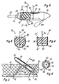
- the catheter system illustrated in FIG. 1 has an infusion chamber 10, which is designed as an elongated, dimensionally stable hollow body and is made of tissue-compatible plastic with an insertion cone 11 at one end. Extending from the insertion cone is an insertable into a vessel and in connection with the interior 12 of the infusion chamber standing catheter 13 continues. At the other end, the infusion chamber is closed off by means of a sealing plug 14 inserted into the chamber in the form of a strong silicone plate.
- the catheter system illustrated in FIGS. 2 and 3 has an infusion chamber 20 made of tissue-compatible plastic, which is also formed as an elongated, dimensionally stable hollow body and is closed at one end by an insertion cone 21.
- the other end of the infusion chamber is closed by means of a sealing plug 24 inserted into it.
- the chamber wall of the infusion chamber is provided with a recess 25 as a puncture window and the sealing plug 24 extends beyond this puncture window in the direction of the insertion cone 21.
- the infusion chamber 20 of the catheter system illustrated in FIGS. 2 and 3 differs from the infusion chamber 10 according to FIG. 1 in that the outer wall is provided on the underside of the chamber with foldable anchoring loops 26 and / or with foldable anchoring pins 27 and in that these anchoring means are provided by a the insertion sleeve 28 surrounding the infusion chamber is directed towards the front, that is to say in the direction of insertion, is pressed against the chamber wall. After the implantation, the insertion sleeve can be pulled off towards the side of the infusion chamber which is closed by means of the sealing plug 24.
- the systems according to FIGS. 1 to 3 are implanted by first inserting a guide wire through a skin puncture opening into an artery, for example, and then pushing the catheter with the infusion chamber over the guide wire, the guide wire being pushed through the The catheter, the infusion chamber and the sealing plug extending on the side remote from the catheter extends through it. After it has been placed in the correct position, the guide wire is withdrawn in a known manner, the through-opening automatically closing in the sealing plug made of silicone or another suitable material closing the rear of the infusion chamber.
- Fig. 1 the catheter system is shown embedded under the skin 16 in the subcutaneous fatty tissue 17 in the implanted state.
- the infusion chamber can be punctured, for example for the purpose of supplying medication, in a simple manner by piercing the skin 16 and the subcutaneous fatty tissue 17 as well as the sealing plug 14 closing the rear of the infusion chamber by means of an injection needle 18.
- the puncture point of the plug 24 closes again automatically after the injection needle has been withdrawn. This is indicated schematically in Fig. 1.
- the insertion sleeve 28 is pulled off from the infusion chamber 20 on the side remote from the insertion cone 21, whereupon the during the implantation on the chamber wall 3 and erect into the patient's subcutaneous fatty tissue adjacent to the underside of the chamber. This achieves the desired stabilization of the position of the infusion chamber.
- the insertion sleeve 28 must be held in its intended position by means of a counter-holder 29 indicated by dash-dotted lines in FIG. 2.
- the infusion chamber 30 is also dimensionally stable and is designed as an elongated sleeve part with a recess 32 which breaks through the sleeve jacket in order to form a puncture window 31.
- the sleeve jacket is closed off by an integrally formed insertion cone 33, while a catheter 35 extends from a likewise approximately conical section 34 at the other end, which catheter 35 is connected permanently or also separably via a plug connection, not shown.
- the catheter-side end part of the sleeve sheath is also provided with a trough 36 which enables tweezers or a clamp to be securely attacked.
- a silicone plug 38 which extends between the two end-side cones 33, 34 and is radially prestressed, is accommodated within the sleeve cover, which completely fills the sleeve cover in the region of its two ends, but on the puncture window 31 or the recess 32 forming it is flattened in the sleeve jacket on the opposite side at 39, so that a through the silicone plug 38 puncturable interior 40 forms for receiving an infusion solution or a drug.
- a channel 42 which ends in the catheter-side end part 34 of the sleeve jacket, extends from this receiving space through the silicone plug 38.
- the silicone plug 38 is provided with a grid 43 made of dimensionally stable thread material integrated in its surface, which prevents the silicone plug from radially escaping in the area of the mentioned recess.
- anchors 44 are arranged on the outside of the sleeve jacket in the form of loops which spread out in the implanted state and secure the infusion chamber 30 after implantation mediate in a patient's subcutaneous fatty tissue.
- the sleeve jacket forming the infusion chamber 30 has an approximately oval shape and in the region of the recess 32 of the sleeve jacket forming the puncture window, both sides of this recess extend over the puncture window 31 protruding beads 45 along which, in the implanted state, allow the position of the puncture window to be felt through the patient's skin.
- longitudinal recesses 46 are provided in the sleeve jacket, in which the anchor loops 44 created during the implantation are received and which at the same time support on the underside form the silicone plug 38 received within the sleeve shell.
- the silicone plug 38 When the infusion chamber is punctured, the silicone plug 38 is pierced through the puncture window 31 by means of a cannula 48, which is indicated in FIGS. 4 and 5. After withdrawing the cannula, the puncture site closes automatically in view of the prestressing of the silicone material, so that refilling of the medicament depot is possible at any time, but medication deposited in the receiving space 40 can only flow out via the catheter.
- FIG. 6 shows in a view similar to FIG. 5 an alternative embodiment with an essentially rectangular cross-section infusion chamber 30 ', which is also provided with only indicated anchoring means 44' in the region of its end remote from the catheter.
- beads 45 ' protrude from both sides of the infusion window 31' and allow the position of the infusion window to be felt through the skin of a patient.
- FIG. 7 shows in a greatly reduced representation compared to FIGS. 4 to 6 the implantation of such an infusion chamber 30, 30 ', one end of which is connected to a catheter 35 already inserted into a vessel.
- the infusion chamber is inserted into a chamber 50 in the subcutaneous fatty tissue 51 of a patient which is expanded from a skin puncture site by means of a dilator (not shown), the end facing away from the catheter, this insertion through the insertion cone 33 at the end of the infusion chamber facing away from the catheter is facilitated.
- the extended A slotted introducer sleeve 52 is inserted into the chamber 50 through the main puncture opening and then the infusion chamber is inserted through the introducer sleeve, with the catheter connected to the infusion chamber extending through a longitudinal slot 53 of the introducer sleeve.
- the infusion chamber 30 can expediently also be provided with a longitudinal rib 54 on the side facing away from the puncture window 31, which then engages in the longitudinal slot 53 of the insertion sleeve 52 and thereby mediates correct placement of the infusion chamber.
- a further pushing aid is a pusher 55, which is provided with a longitudinal slot 56 corresponding to the longitudinal slot 53 of the insertion sleeve 52 and by means of which the infusion chamber connected to the catheter can be inserted through the insertion sleeve 52 into the prepared receiving chamber 50.
Landscapes
- Health & Medical Sciences (AREA)
- Heart & Thoracic Surgery (AREA)
- Pulmonology (AREA)
- Engineering & Computer Science (AREA)
- Anesthesiology (AREA)
- Biomedical Technology (AREA)
- Hematology (AREA)
- Life Sciences & Earth Sciences (AREA)
- Animal Behavior & Ethology (AREA)
- General Health & Medical Sciences (AREA)
- Public Health (AREA)
- Veterinary Medicine (AREA)
- Media Introduction/Drainage Providing Device (AREA)
- Infusion, Injection, And Reservoir Apparatuses (AREA)
Priority Applications (2)
| Application Number | Priority Date | Filing Date | Title |
|---|---|---|---|
| DE89108034T DE58905847D1 (de) | 1989-05-03 | 1989-05-03 | Vorrichtung mit implantierbarer Infusionskammer und einem sich von dieser forterstreckenden Katheter. |
| AT89108034T ATE95436T1 (de) | 1989-05-03 | 1989-05-03 | Vorrichtung mit implantierbarer infusionskammer und einem sich von dieser forterstreckenden katheter. |
Applications Claiming Priority (2)
| Application Number | Priority Date | Filing Date | Title |
|---|---|---|---|
| DE3738398 | 1987-11-12 | ||
| DE19883837779 DE3837779A1 (de) | 1987-11-12 | 1988-11-08 | Kathetersystem mit infusionskammer |
Publications (2)
| Publication Number | Publication Date |
|---|---|
| EP0395778A1 EP0395778A1 (de) | 1990-11-07 |
| EP0395778B1 true EP0395778B1 (de) | 1993-10-06 |
Family
ID=25861712
Family Applications (1)
| Application Number | Title | Priority Date | Filing Date |
|---|---|---|---|
| EP19890108034 Expired - Lifetime EP0395778B1 (de) | 1987-11-12 | 1989-05-03 | Vorrichtung mit implantierbarer Infusionskammer und einem sich von dieser forterstreckenden Katheter |
Country Status (2)
| Country | Link |
|---|---|
| EP (1) | EP0395778B1 (enExample) |
| DE (1) | DE3837779A1 (enExample) |
Families Citing this family (13)
| Publication number | Priority date | Publication date | Assignee | Title |
|---|---|---|---|---|
| DE3837779A1 (de) * | 1987-11-12 | 1989-05-24 | Ernst Peter Prof Dr M Strecker | Kathetersystem mit infusionskammer |
| US5207644A (en) * | 1991-03-04 | 1993-05-04 | Strecker Ernst P | Device with implantable infusion chamber and a catheter extending therefrom |
| US5183033A (en) * | 1991-07-15 | 1993-02-02 | Wilk Peter J | Surgical instrument assembly and apparatus and surgical method |
| US5176692A (en) * | 1991-12-09 | 1993-01-05 | Wilk Peter J | Method and surgical instrument for repairing hernia |
| US5211624A (en) * | 1991-12-09 | 1993-05-18 | Cinberg James Z | Surgical closure device method |
| US5232440A (en) * | 1992-02-26 | 1993-08-03 | Wilk Peter J | Method and device for draining abscess |
| DE4221390C1 (enExample) * | 1992-06-30 | 1993-04-01 | Haindl, Hans, Dr.Med., 3015 Wennigsen, De | |
| US5304117A (en) * | 1992-11-27 | 1994-04-19 | Wilk Peter J | Closure method for use in laparoscopic surgery |
| WO1994015663A1 (en) * | 1992-12-30 | 1994-07-21 | Brown University Research Foundation | Implantable therapy systems and methods |
| WO1995023623A1 (en) * | 1994-03-04 | 1995-09-08 | Mentor Corporation | Self-sealing injection sites and method of manufacture |
| DE4423706C1 (de) * | 1994-06-24 | 1996-02-22 | Florian Dr Med Krug | Subcutan implantierbares Portsystem |
| DE4436350C1 (de) * | 1994-10-12 | 1996-02-29 | Fresenius Ag | Implantierbares medizinisches Gerät |
| JP2002518140A (ja) | 1998-06-25 | 2002-06-25 | シー・アール・バード・インコーポレーテッド | エラストマーバルブを備える医療装置 |
Family Cites Families (9)
| Publication number | Priority date | Publication date | Assignee | Title |
|---|---|---|---|---|
| US3971376A (en) * | 1973-02-26 | 1976-07-27 | Ceskoslovenska Akademie Ved | Method and apparatus for introducing fluids into the body |
| DE3102993C2 (de) * | 1981-01-29 | 1983-12-15 | Peter Prof. Dr.med. 8000 München Bottermann | Subkutan implantierbare Vorrichtung für die Zuführung flüssiger Arzneimittel |
| DE3309788C2 (de) * | 1983-03-18 | 1985-12-05 | Karl Dr. 6301 Pohlheim Aigner | Implantierbarer Zuspritzkatheder |
| DE3447642C1 (de) * | 1984-12-28 | 1986-09-18 | Bernhard M. Dr. 5600 Wuppertal Cramer | Lenkbarer Fuehrungsdraht fuer Katheter |
| DE3528878A1 (de) * | 1985-08-12 | 1987-02-19 | Sanden Hasko Von Dipl Ing Dr M | Intraperitonealkatheter fuer die zufuehrung fluessiger arzneimittel, insbesondere von insulin |
| US4751926A (en) * | 1986-09-12 | 1988-06-21 | Dow Corning Wright Corporation | Instrument for subcutaneous insertion of an injection reservoir |
| US4802479A (en) * | 1986-10-31 | 1989-02-07 | C. R. Bard, Inc. | Hand-held instrument for implanting, dispensing, and inflating an inflatable membrane |
| FR2608916B1 (fr) * | 1986-12-26 | 1989-10-20 | Mai Christian | Prothese a expansion tissulaire |
| DE3837779A1 (de) * | 1987-11-12 | 1989-05-24 | Ernst Peter Prof Dr M Strecker | Kathetersystem mit infusionskammer |
-
1988
- 1988-11-08 DE DE19883837779 patent/DE3837779A1/de active Granted
-
1989
- 1989-05-03 EP EP19890108034 patent/EP0395778B1/de not_active Expired - Lifetime
Also Published As
| Publication number | Publication date |
|---|---|
| EP0395778A1 (de) | 1990-11-07 |
| DE3837779A1 (de) | 1989-05-24 |
| DE3837779C2 (enExample) | 1991-02-07 |
Similar Documents
| Publication | Publication Date | Title |
|---|---|---|
| DE69603157T2 (de) | Implantierbare zugangsvorrichtung | |
| DE4306850C1 (de) | Implantat, insbesondere zum Verschluß von Trokareinstichstellen | |
| DE69609064T2 (de) | Implantierbarer katheter | |
| DE602004008021T2 (de) | Flexible Injektionsöffnung | |
| DE69835603T2 (de) | Führungsdrahtgeeignete Einspritzportanordnung | |
| US5207644A (en) | Device with implantable infusion chamber and a catheter extending therefrom | |
| EP0395778B1 (de) | Vorrichtung mit implantierbarer Infusionskammer und einem sich von dieser forterstreckenden Katheter | |
| DE69123817T2 (de) | Gerät zum Abdichten von Punkturwunden | |
| DE4236210C1 (de) | Schlauchförmiges Implantat zur Verwendung bei der perkutanen Nahrungszufuhr | |
| DE69329660T2 (de) | IMPLANTIERBARE ANSATZSTüCKE | |
| DE69224892T2 (de) | Implantierbare Infusionsvorrichtung | |
| DE69322370T2 (de) | Laparoskopisches einstellbares Magenband | |
| DE69733835T2 (de) | System zum verschliessen einer vaskulären wunde | |
| DE60306502T2 (de) | Vaskuläre kupplungsvorrichtung | |
| DE3780378T2 (de) | Zum verabreichen therapeutischer substanzen geeignete vorrichtung. | |
| DE69124164T2 (de) | Implantierbare infusionsvorrichtung | |
| DE60029404T2 (de) | Wirkstoffabgabesysteme | |
| EP0679408A2 (de) | Vorrichtung zum Einführen eines Katheters in einen Körperhohlraum | |
| EP0654976A1 (de) | Verwendung von und vorrichtung zum einbringen von fibrinkleber in einen stichkanal. | |
| DE4335099A1 (de) | Verfahren und Vorrichtung zum Beschränken des Zuganges zu einem Septum | |
| DE2430131A1 (de) | Vorrichtung zur superapubischen katheterisierung | |
| DE19745654A1 (de) | Vorrichtung zur subkutanen Infusion und deren Verwendung | |
| DE69318821T2 (de) | Katheter zur Versorgung des Penis mit Medikamenten | |
| EP1184010A2 (de) | Kammerwasser-Drainagevorrichtung | |
| DE60311268T2 (de) | Gerät zum abdichten von Punkturwunden durch Reduktion des Punkturumfangs |
Legal Events
| Date | Code | Title | Description |
|---|---|---|---|
| PUAI | Public reference made under article 153(3) epc to a published international application that has entered the european phase |
Free format text: ORIGINAL CODE: 0009012 |
|
| AK | Designated contracting states |
Kind code of ref document: A1 Designated state(s): AT BE CH DE ES FR GB GR IT LI LU NL SE |
|
| 17P | Request for examination filed |
Effective date: 19901215 |
|
| 17Q | First examination report despatched |
Effective date: 19920324 |
|
| GRAA | (expected) grant |
Free format text: ORIGINAL CODE: 0009210 |
|
| AK | Designated contracting states |
Kind code of ref document: B1 Designated state(s): AT BE CH DE ES FR GB GR IT LI LU NL SE |
|
| PG25 | Lapsed in a contracting state [announced via postgrant information from national office to epo] |
Ref country code: IT Free format text: LAPSE BECAUSE OF FAILURE TO SUBMIT A TRANSLATION OF THE DESCRIPTION OR TO PAY THE FEE WITHIN THE PRE;WARNING: LAPSES OF ITALIAN PATENTS WITH EFFECTIVE DATE BEFORE 2007 MAY HAVE OCCURRED AT ANY TIME BEFORE 2007. THE CORRECT EFFECTIVE DATE MAY BE DIFFERENT FROM THE ONE RECORDED.SCRIBED TIME-LIMIT Effective date: 19931006 Ref country code: ES Free format text: THE PATENT HAS BEEN ANNULLED BY A DECISION OF A NATIONAL AUTHORITY Effective date: 19931006 Ref country code: BE Effective date: 19931006 Ref country code: GR Free format text: LAPSE BECAUSE OF FAILURE TO SUBMIT A TRANSLATION OF THE DESCRIPTION OR TO PAY THE FEE WITHIN THE PRESCRIBED TIME-LIMIT Effective date: 19931006 Ref country code: SE Effective date: 19931006 Ref country code: NL Effective date: 19931006 |
|
| REF | Corresponds to: |
Ref document number: 95436 Country of ref document: AT Date of ref document: 19931015 Kind code of ref document: T |
|
| REF | Corresponds to: |
Ref document number: 58905847 Country of ref document: DE Date of ref document: 19931111 |
|
| GBT | Gb: translation of ep patent filed (gb section 77(6)(a)/1977) |
Effective date: 19940112 |
|
| ET | Fr: translation filed | ||
| NLV1 | Nl: lapsed or annulled due to failure to fulfill the requirements of art. 29p and 29m of the patents act | ||
| PG25 | Lapsed in a contracting state [announced via postgrant information from national office to epo] |
Ref country code: AT Effective date: 19940503 |
|
| PG25 | Lapsed in a contracting state [announced via postgrant information from national office to epo] |
Ref country code: LI Effective date: 19940531 Ref country code: LU Free format text: LAPSE BECAUSE OF NON-PAYMENT OF DUE FEES Effective date: 19940531 Ref country code: CH Effective date: 19940531 |
|
| PLBE | No opposition filed within time limit |
Free format text: ORIGINAL CODE: 0009261 |
|
| STAA | Information on the status of an ep patent application or granted ep patent |
Free format text: STATUS: NO OPPOSITION FILED WITHIN TIME LIMIT |
|
| 26N | No opposition filed | ||
| REG | Reference to a national code |
Ref country code: CH Ref legal event code: PL |
|
| REG | Reference to a national code |
Ref country code: GB Ref legal event code: IF02 |
|
| PGFP | Annual fee paid to national office [announced via postgrant information from national office to epo] |
Ref country code: DE Payment date: 20030416 Year of fee payment: 15 |
|
| PGFP | Annual fee paid to national office [announced via postgrant information from national office to epo] |
Ref country code: FR Payment date: 20030418 Year of fee payment: 15 |
|
| PGFP | Annual fee paid to national office [announced via postgrant information from national office to epo] |
Ref country code: GB Payment date: 20030502 Year of fee payment: 15 |
|
| PG25 | Lapsed in a contracting state [announced via postgrant information from national office to epo] |
Ref country code: GB Free format text: LAPSE BECAUSE OF NON-PAYMENT OF DUE FEES Effective date: 20040503 |
|
| PG25 | Lapsed in a contracting state [announced via postgrant information from national office to epo] |
Ref country code: DE Free format text: LAPSE BECAUSE OF NON-PAYMENT OF DUE FEES Effective date: 20041201 |
|
| GBPC | Gb: european patent ceased through non-payment of renewal fee |
Effective date: 20040503 |
|
| PG25 | Lapsed in a contracting state [announced via postgrant information from national office to epo] |
Ref country code: FR Free format text: LAPSE BECAUSE OF NON-PAYMENT OF DUE FEES Effective date: 20050131 |
|
| REG | Reference to a national code |
Ref country code: FR Ref legal event code: ST |