EP0395147A2 - Bremsklotzhalteranordnung - Google Patents
Bremsklotzhalteranordnung Download PDFInfo
- Publication number
- EP0395147A2 EP0395147A2 EP90200974A EP90200974A EP0395147A2 EP 0395147 A2 EP0395147 A2 EP 0395147A2 EP 90200974 A EP90200974 A EP 90200974A EP 90200974 A EP90200974 A EP 90200974A EP 0395147 A2 EP0395147 A2 EP 0395147A2
- Authority
- EP
- European Patent Office
- Prior art keywords
- brake block
- block holder
- push rod
- brake
- hangers
- Prior art date
- Legal status (The legal status is an assumption and is not a legal conclusion. Google has not performed a legal analysis and makes no representation as to the accuracy of the status listed.)
- Ceased
Links
- 239000000725 suspension Substances 0.000 claims abstract description 9
- 230000005540 biological transmission Effects 0.000 abstract description 4
- 230000009467 reduction Effects 0.000 description 3
- 238000006722 reduction reaction Methods 0.000 description 3
- 230000000694 effects Effects 0.000 description 1
- 239000000463 material Substances 0.000 description 1
- 238000007789 sealing Methods 0.000 description 1
Images

Classifications
-
- F—MECHANICAL ENGINEERING; LIGHTING; HEATING; WEAPONS; BLASTING
- F16—ENGINEERING ELEMENTS AND UNITS; GENERAL MEASURES FOR PRODUCING AND MAINTAINING EFFECTIVE FUNCTIONING OF MACHINES OR INSTALLATIONS; THERMAL INSULATION IN GENERAL
- F16D—COUPLINGS FOR TRANSMITTING ROTATION; CLUTCHES; BRAKES
- F16D65/00—Parts or details
- F16D65/02—Braking members; Mounting thereof
- F16D65/04—Bands, shoes or pads; Pivots or supporting members therefor
- F16D65/06—Bands, shoes or pads; Pivots or supporting members therefor for externally-engaging brakes
-
- B—PERFORMING OPERATIONS; TRANSPORTING
- B61—RAILWAYS
- B61H—BRAKES OR OTHER RETARDING DEVICES SPECIALLY ADAPTED FOR RAIL VEHICLES; ARRANGEMENT OR DISPOSITION THEREOF IN RAIL VEHICLES
- B61H1/00—Applications or arrangements of brakes with a braking member or members co-operating with the periphery of the wheel rim, a drum, or the like
- B61H1/003—Applications or arrangements of brakes with a braking member or members co-operating with the periphery of the wheel rim, a drum, or the like with an actuator directly acting on a brake head
Definitions
- This invention relates to a brake block holder arrangement, comprising a brake block holder for transmitting an axial brake force from an axially movable push rod of a brake actuator and being pivotally attached to brake block hangers, which are suspended from a suspension bracket on the actuator, wherein the brake force is transmitted from the push rod via a push rod head thereon in direct contact with a generally tube-shaped portion of the brake block holder around its shaft for pivotal connection to the hangers.
- the arrangement is primarily intended for use on a rail vehicle.
- the guiding and torque transmission can according to the invention be attained in that the push rod head has an upper and a lower extension with a width corresponding to the distance between the side-walls of the brake block holder and in that one of the extensions is provided with a laterally movable cross piece having toothed end surfaces for cooperation with spring biassed toothed segments, rotatably arranged in the inner surfaces of the brake block holder side-walls.
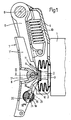
- Fig 1 is a side view, partly in section, of a brake block holder suspension according to the invention
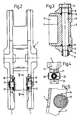
- Fig 2 is a front view (from the right in Fig 1) of the brake block holder being a part of the suspension shown in Fig 1
- Fig 3 is a section along the line III-III in Fig 1 through the brake block holder
- Fig 4 is a detail view along the line IV-IV in Fig 1
- Fig 5 is a detail view along the line V-V in Fig 2-5 being to a larger scale than Fig 1.
- Figs 6 and 7 are a side view and a section along the line VII-VII in Fig 6, respectively, of a prior art suspension.
- a conventional rail vehicle brake unit or brake actuator 1 is provided with an axially movable push rod 2, as is well known in the art. Integral with the push rod 2 is a push rod head 3 to be described below. A rubber bellows 3′ is arranged between the brake unit 1 and the push rod head 3.
- a suspension bracket 4 is attached to the brake unit 1.
- a divided brake block hanger 5 is pivotally arranged in the bracket 4 by means of a shaft 6.
- a brake block holder 7 is pivotally attached to the brake block hanger 5 by means of a shaft 8, which is to be further described below under reference to Fig 3.
- the shaft 8 extends through a generally tube-shaped portion of the brake block holder 7, as most clearly appears from Fig 1.
- the brake block holder 7 is provided with an arcuate or cylindrical rear surface 9 in force transmitting contact with the push rod head 3.
- a draw spring 10 is arranged between the bracket 4 and the hanger 5 to keep the surface 9 in constant contact with the push rod head 3.
- the push rod 2 and the brake block holder 7 may be flexibly interconnected by for example a rubber band.
- the brake block holder 7 is to be provided with a replacable brake block, which is not shown in the drawings.
- the push rod head 3 has a substantially planar surface in contact with the cylindrical surface 9 of the brake block holder 7.
- the head 3 has an upper extension 11 and a lower extension 12.
- the width of these two extensions 11 and 12 corresponds to the inner distance between two side-walls 7′ of the brake block holder 7. In this way an advantageous guiding and torque transmission between the push rod 2 and the brake block holder 7 is obtained.
- the pivotal connection between the brake block hangers 5 and the brake block holder 7 has the following design:
- the shaft 8 is a cylindrical part of a screw 13, which has a threaded portion near its head for play-less engagement with an internal thread of the upper hanger 5 in Fig 3.
- the screw 13 has a shoulder 13′ for the lower hanger 5, so that the brake block holder 7 may pivot between the two hangers 5.
- the screw is provided with a thread, with which a conical nut 14 engages for eliminating the play with the hanger 5 and accordingly the need for a separate bushing, adding to the volume.
- Sealing O-rings 15 are arranged around the screw 13 at each end of the brake block holder 7.
- Each side-wall 7′ of the brake block holder 7 is provided with an internal, rotatable, toothed segment 16.
- the segments 16 are biassed towards each other by springs 17.
- a pin 18 arranged in the wall 7′ and cooperating with a circumferential notch in the segment 16 has the effect that the segment can only rotate a small angular distance and has the right position for its intended function to be described below.
- a cross piece 19 Cooperating with the toothed segments 16 is a cross piece 19, which is laterally movably arranged towards the end of the lower extension 12 of the push rod head 3.
- the extension 12 is provided with a transverse groove intended for the cross piece 19 and covered by a lid 20, which is attached by means of screws or rivets 21.
- the cross piece 19 is provided with O-rings 22 or the like for reducing play and thus wear.
- the two ends of the cross piece 19 are provided with teeth for cooperation with the teeth of the segments 16, and the length of the cross piece 19 is slightly larger than the distance between the segments 16 in their rest position as shown in Fig 2.
- the arrangement may be provided at the upper extension 11.
- the brake block holder 7 At each brake application the brake block holder 7 will be pushed forward (to the left in Fig 1) by the push rod 2 with its head 3. The movement of the push rod 2 is axial, whereas that of the brake block holder 7 is arcuate due to its suspension. The surface 9 will accordingly slide on the planar surface of the head 3. The brake block holder 7 is guided by the extensions 11 and 12 of the head 3. By the engagement with the wheel to be braked the brake block holder 7 will adopt a certain position, and any changed position is made possible by relative movements between the toothed surfaces of the cross piece 19 and the segments 16. The position attained is then maintained at least until the next brake application.
- a prior art arrangement is shown in Figs 6 and 7. Many parts are similar to those depicted in Fig 1, and only a brief description is given.
- a suspension bracket 30 is attached to a brake unit 31 having an axially movable push rod 32.
- Brake block hangers 33 are pivotally suspended from the bracket 30, and a brake block holder 34 is pivotally attached to the hangers 32, a conventional friction device 35 being arranged between the hangers 33 and the brake block holder 34, which means that the holder 34 follows the hangers in their arcuate movements.
- the pivotal connection between the hangers 32 and the brake block holder 34 is by means of a shaft 36, on which also a cube 37 is arranged between the two legs of the holder 34.
- the cube 37 is provided with a V-shaped groove for force transmitting cooperation with the V-shaped end of the push rod 32. Constant contact between the cube 37 and the push rod 32 is guaranteed by a spring 38.
- the push rod 32 provides lateral guiding for the brake block holder 34, which still can perform its arcuate movement in spite of the axial movement of the push rod.
- each leg of the brake block holder 34 are substantially planar, and each leg is provided with a rather big notch for a mounting protection on the brake block (not shown) to be releasably attached to the brake block holder.
- the distance between the hole for the shaft 36 and the notch must be quite substantial.
- the material thickness of the brake block holder 7 is increased, as appears from Fig 2, in this main force transmitting region, and the notch 7 ⁇ referred to above is provided with lateral walls.
- Fig 3 which is a section through this critical region of the brake block holder 7, clearly shows that the width (or dimension from right to left therein) is minimal taking the depth of the notch 7 ⁇ into account. In reality these measures have made it possible to reduce the width (or the distance from the end of the push rod 2 to the brake block holder surface accomodating the brake block) by some 25 mm.
- the front surface of the brake block hangers 5 and the brake block holder 7 are slanted so as not to interfere with a wheel flange during braking.
Landscapes
- Engineering & Computer Science (AREA)
- General Engineering & Computer Science (AREA)
- Mechanical Engineering (AREA)
- Braking Arrangements (AREA)
Applications Claiming Priority (2)
| Application Number | Priority Date | Filing Date | Title |
|---|---|---|---|
| SE8901537A SE466906B (sv) | 1989-04-27 | 1989-04-27 | Bromsklotshaallararrangemang |
| SE8901537 | 1989-04-27 |
Publications (2)
| Publication Number | Publication Date |
|---|---|
| EP0395147A2 true EP0395147A2 (de) | 1990-10-31 |
| EP0395147A3 EP0395147A3 (de) | 1991-11-06 |
Family
ID=20375820
Family Applications (1)
| Application Number | Title | Priority Date | Filing Date |
|---|---|---|---|
| EP19900200974 Ceased EP0395147A3 (de) | 1989-04-27 | 1990-04-19 | Bremsklotzhalteranordnung |
Country Status (4)
| Country | Link |
|---|---|
| US (1) | US5062505A (de) |
| EP (1) | EP0395147A3 (de) |
| JP (1) | JPH02296021A (de) |
| SE (1) | SE466906B (de) |
Cited By (1)
| Publication number | Priority date | Publication date | Assignee | Title |
|---|---|---|---|---|
| EP3536578A1 (de) * | 2011-04-06 | 2019-09-11 | Faiveley Transport Nordic AB | Schienenfahrzeugbremsaktuator mit übertragungsmittel |
Families Citing this family (5)
| Publication number | Priority date | Publication date | Assignee | Title |
|---|---|---|---|---|
| SE468085B (sv) * | 1991-03-11 | 1992-11-02 | Wabco Holdings Sab | Tryckkraftoeverfoerande anordning vid en bromsaktuator |
| SE517690C2 (sv) * | 1999-11-18 | 2002-07-02 | Sab Wabco Ab | Blockhållare för en boggibroms |
| CN100376443C (zh) * | 2003-07-21 | 2008-03-26 | 阿塞泰克股份有限公司 | 枢转地连接制动头至制动梁的枢转接头 |
| DE102009006290A1 (de) * | 2009-01-27 | 2010-07-29 | Knorr-Bremse Systeme für Schienenfahrzeuge GmbH | Verbindung eines Bremsbelages mit einem Belaghalter |
| US8360214B2 (en) * | 2009-04-09 | 2013-01-29 | Wabtec Holding Corp. | Brake shoe support assembly and method |
Citations (3)
| Publication number | Priority date | Publication date | Assignee | Title |
|---|---|---|---|---|
| FR461075A (fr) * | 1912-08-05 | 1913-12-18 | Adolphe Chaumont | Dispositif de sabot de frein pivotant, s'ajustant automatiquement, pour véhicules de chemins de fer et de tramways |
| FR973933A (de) * | 1951-02-16 | |||
| EP0137431A2 (de) * | 1983-10-11 | 1985-04-17 | Knorr-Bremse Ag | Klotzbremse für Schienenfahrzeuge |
Family Cites Families (4)
| Publication number | Priority date | Publication date | Assignee | Title |
|---|---|---|---|---|
| US3447647A (en) * | 1967-09-05 | 1969-06-03 | Westinghouse Air Brake Co | Hydraulic-pneumatic tread brake unit for railway car trucks |
| SE414384B (sv) * | 1978-11-02 | 1980-07-28 | Sab Ind Ab | Anordning vid en bromsaktuator |
| SE434377B (sv) * | 1979-04-20 | 1984-07-23 | Sab Ind Ab | Bromsblockhallare hos ett jernvegsfordon |
| SE446709B (sv) * | 1983-12-21 | 1986-10-06 | Sab Nife Ab | Klotsbromsaktuator for ett relsfordon |
-
1989
- 1989-04-27 SE SE8901537A patent/SE466906B/sv not_active IP Right Cessation
-
1990
- 1990-04-19 EP EP19900200974 patent/EP0395147A3/de not_active Ceased
- 1990-04-19 US US07/511,338 patent/US5062505A/en not_active Expired - Fee Related
- 1990-04-26 JP JP2111581A patent/JPH02296021A/ja active Pending
Patent Citations (3)
| Publication number | Priority date | Publication date | Assignee | Title |
|---|---|---|---|---|
| FR973933A (de) * | 1951-02-16 | |||
| FR461075A (fr) * | 1912-08-05 | 1913-12-18 | Adolphe Chaumont | Dispositif de sabot de frein pivotant, s'ajustant automatiquement, pour véhicules de chemins de fer et de tramways |
| EP0137431A2 (de) * | 1983-10-11 | 1985-04-17 | Knorr-Bremse Ag | Klotzbremse für Schienenfahrzeuge |
Cited By (1)
| Publication number | Priority date | Publication date | Assignee | Title |
|---|---|---|---|---|
| EP3536578A1 (de) * | 2011-04-06 | 2019-09-11 | Faiveley Transport Nordic AB | Schienenfahrzeugbremsaktuator mit übertragungsmittel |
Also Published As
| Publication number | Publication date |
|---|---|
| EP0395147A3 (de) | 1991-11-06 |
| SE8901537L (sv) | 1990-10-28 |
| US5062505A (en) | 1991-11-05 |
| SE8901537D0 (sv) | 1989-04-27 |
| SE466906B (sv) | 1992-04-27 |
| JPH02296021A (ja) | 1990-12-06 |
Similar Documents
| Publication | Publication Date | Title |
|---|---|---|
| AU684638B2 (en) | Adjustable leverage brake lever | |
| EP0646520A2 (de) | Zugspannungseinheit für einen Fahrradbremsbetätigungszug | |
| EP0395147A2 (de) | Bremsklotzhalteranordnung | |
| EP0287785A3 (de) | Kombination von Kunststoffederführung und Rückstossbremse für automatische Pistolen | |
| EP0046619A1 (de) | Schienenfahrzeug-Scheibenbremsanordnung | |
| US4776439A (en) | Disc brakes | |
| EP0018050B2 (de) | Halterung für einen Eisenbahn-Bremsklotz | |
| US4287968A (en) | Device at a brake actuator | |
| US5277280A (en) | Thrust force transmission device at a brake actuator | |
| EP0077586B1 (de) | Halterung für einen Eisenbahnbremsklotz | |
| AU646150B2 (en) | A rail vehicle brake actuator with a brake block holder | |
| GB2057074A (en) | Disc brake | |
| ES280728U (es) | Muelle telescopico a gas ajustable longitudinalmente. | |
| EP0503724A2 (de) | Schienenfahrzeugbremsbedienungseinrichtung mit Bremsklotzhalter | |
| DE4036401A1 (de) | Geraeuschdaempfer fuer scheibenbremsen | |
| EP0844160B1 (de) | Laufflächen- Konditioniereinheit | |
| SU889421A1 (ru) | Захват манипул тора | |
| ES8407222A1 (es) | Perfeccionamientos en las barras de reaccion de rendimiento mecanico variable | |
| KR0180872B1 (ko) | 클러치용 클레비스 핀 구조물 | |
| EP0200627A2 (de) | Betätigungseinrichtung für Doppelhauptzylinder | |
| GB2065804A (en) | Brake Actuation Mechanism | |
| KR19980021163U (ko) | 자동차 액셀레이터용 페달로드의 로드서포트 |
Legal Events
| Date | Code | Title | Description |
|---|---|---|---|
| PUAI | Public reference made under article 153(3) epc to a published international application that has entered the european phase |
Free format text: ORIGINAL CODE: 0009012 |
|
| AK | Designated contracting states |
Kind code of ref document: A2 Designated state(s): DE FR GB IT |
|
| RAP1 | Party data changed (applicant data changed or rights of an application transferred) |
Owner name: SAB WABCO HOLDINGS B.V. |
|
| PUAL | Search report despatched |
Free format text: ORIGINAL CODE: 0009013 |
|
| AK | Designated contracting states |
Kind code of ref document: A3 Designated state(s): DE FR GB IT |
|
| 17P | Request for examination filed |
Effective date: 19910925 |
|
| 17Q | First examination report despatched |
Effective date: 19930420 |
|
| STAA | Information on the status of an ep patent application or granted ep patent |
Free format text: STATUS: THE APPLICATION HAS BEEN REFUSED |
|
| 18R | Application refused |
Effective date: 19940606 |