EP0844160B1 - Laufflächen- Konditioniereinheit - Google Patents
Laufflächen- Konditioniereinheit Download PDFInfo
- Publication number
- EP0844160B1 EP0844160B1 EP97120427A EP97120427A EP0844160B1 EP 0844160 B1 EP0844160 B1 EP 0844160B1 EP 97120427 A EP97120427 A EP 97120427A EP 97120427 A EP97120427 A EP 97120427A EP 0844160 B1 EP0844160 B1 EP 0844160B1
- Authority
- EP
- European Patent Office
- Prior art keywords
- piston rod
- block holder
- pivot sleeve
- block
- holder
- Prior art date
- Legal status (The legal status is an assumption and is not a legal conclusion. Google has not performed a legal analysis and makes no representation as to the accuracy of the status listed.)
- Expired - Lifetime
Links
Images

Classifications
-
- B—PERFORMING OPERATIONS; TRANSPORTING
- B61—RAILWAYS
- B61H—BRAKES OR OTHER RETARDING DEVICES SPECIALLY ADAPTED FOR RAIL VEHICLES; ARRANGEMENT OR DISPOSITION THEREOF IN RAIL VEHICLES
- B61H1/00—Applications or arrangements of brakes with a braking member or members co-operating with the periphery of the wheel rim, a drum or the like
- B61H1/003—Applications or arrangements of brakes with a braking member or members co-operating with the periphery of the wheel rim, a drum or the like with an actuator directly acting on a brake head
-
- B—PERFORMING OPERATIONS; TRANSPORTING
- B60—VEHICLES IN GENERAL
- B60T—VEHICLE BRAKE CONTROL SYSTEMS OR PARTS THEREOF; BRAKE CONTROL SYSTEMS OR PARTS THEREOF, IN GENERAL; ARRANGEMENT OF BRAKING ELEMENTS ON VEHICLES IN GENERAL; PORTABLE DEVICES FOR PREVENTING UNWANTED MOVEMENT OF VEHICLES; VEHICLE MODIFICATIONS TO FACILITATE COOLING OF BRAKES
- B60T17/00—Component parts, details, or accessories of power brake systems not covered by groups B60T8/00, B60T13/00 or B60T15/00, or presenting other characteristic features
- B60T17/08—Brake cylinders other than ultimate actuators
- B60T17/081—Single service brake actuators
-
- F—MECHANICAL ENGINEERING; LIGHTING; HEATING; WEAPONS; BLASTING
- F16—ENGINEERING ELEMENTS AND UNITS; GENERAL MEASURES FOR PRODUCING AND MAINTAINING EFFECTIVE FUNCTIONING OF MACHINES OR INSTALLATIONS; THERMAL INSULATION IN GENERAL
- F16D—COUPLINGS FOR TRANSMITTING ROTATION; CLUTCHES; BRAKES
- F16D65/00—Parts or details
- F16D65/0037—Devices for conditioning friction surfaces, e.g. cleaning or abrasive elements
-
- F—MECHANICAL ENGINEERING; LIGHTING; HEATING; WEAPONS; BLASTING
- F16—ENGINEERING ELEMENTS AND UNITS; GENERAL MEASURES FOR PRODUCING AND MAINTAINING EFFECTIVE FUNCTIONING OF MACHINES OR INSTALLATIONS; THERMAL INSULATION IN GENERAL
- F16D—COUPLINGS FOR TRANSMITTING ROTATION; CLUTCHES; BRAKES
- F16D65/00—Parts or details
- F16D65/02—Braking members; Mounting thereof
- F16D65/04—Bands, shoes or pads; Pivots or supporting members therefor
- F16D65/06—Bands, shoes or pads; Pivots or supporting members therefor for externally-engaging brakes
- F16D65/062—Bands, shoes or pads; Pivots or supporting members therefor for externally-engaging brakes engaging the tread of a railway wheel
-
- F—MECHANICAL ENGINEERING; LIGHTING; HEATING; WEAPONS; BLASTING
- F16—ENGINEERING ELEMENTS AND UNITS; GENERAL MEASURES FOR PRODUCING AND MAINTAINING EFFECTIVE FUNCTIONING OF MACHINES OR INSTALLATIONS; THERMAL INSULATION IN GENERAL
- F16D—COUPLINGS FOR TRANSMITTING ROTATION; CLUTCHES; BRAKES
- F16D65/00—Parts or details
- F16D65/14—Actuating mechanisms for brakes; Means for initiating operation at a predetermined position
Definitions
- the present invention relates to a tread conditioning unit for applying a brake block against a tread of a rail vehicle wheel, comprising a fluid operated cylinder having a piston with a piston rod, as well as a block holder for the brake block
- the block holder for the brake block is pivotably connected to the piston rod by means comprising a pivot sleeve, which is rotatably attached in the end of the tubular piston rod facing the block holder, and whose axis is perpendicular to the axis of the piston rod and crosses two openings facing each other in the end of the piston rod, the block holder being provided with a horizontal groove of semicircular cross section for engagement with the pivot sleeve and means being provided for keeping the block holder connected to the pivot sleeve.
- connection means comprise a screw extending through a bore in the block holder, further through an opening in the pivot sleeve and into a threaded hole in a retaining pin extending through the openings and the pivot sleeve.
- a rubber bushing may be arranged between the block holder and the end of the piston rod for holding the block holder in a vertical position during application and for providing vibration damping.
- the block holder of the unit may under certain circumstances be exposed to shock forces from the wheel flanges.
- the piston rod can deflect elastically under these torques and be returned to its original position in that it is guided in an end flange of the unit housing by means of a guide bushing, which is spring biassed into engagement with the end flange and has axial teeth engaging notches in the end flange, said teeth having steeper portions, so that after a relative movement between the end flange and the guide bushing a return force from the spring bias is exerted on the guide bushing.
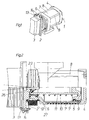
- a tread conditioning unit as shown in perspective in Fig 1 and in a sectioned side view in Fig 2 is to be mounted in the undercarriage of a normally disc braked rail vehicle at a vehicle wheel, whose tread is to be conditioned from time to time for the main purpose of keeping the adhesion between the wheel and the rail on which it rolls at an appropriate level.
- such a unit is comprised of a fluid operated, normally pneumatic cylinder 1 and a block holder 2 provided with a brake block 3 for engagement with a rail vehicle wheel when applied.
- the unit is in Fig 1 shown standing, but normally it is suspended from a suitable part of the vehicle undercarriage.
- the cylinder 1 may be constructed of an end flange 4, a cylinder tube 5 and a base flange 6, which all may be made of aluminium.
- a gaiter 7 of rubber or plastic may enclose the tube 5.
- This gaiter 7 may be provided with one or several draining holes 7'. The different cylinder parts are held together by screws 8.
- a return spring 10 is arranged around a tubular piston rod 11 attached to the piston 9.
- the block holder 2 is pivotably connected to the piston rod 11 in a way to be further described.
- a bellows 12 is arranged between the base flange 6 and the block holder 2.
- the brake block 3 is removably attached to the block holder 2 in a conventional way, such as by means of a retainer plate 13 and screws 14.
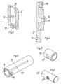
- Fig 3 shows the block holder 2 from the brake block side. It has a lower attachment 15 for the brake block 3 and threaded holes 16 for the screws 14. These can also be seen in Fig 4.
- Fig 5 shows the tubular piston rod 11, which is provided with a longitudinal groove 17 for guiding engagement with a projection 27" in a guide bushing 27 in the base flange 6, the bushing to be described below under reference to Figs 10-12.
- the piston rod is provided with two coaxial circular side openings 18.
- a pivot sleeve 19, shown in Fig 6, can be inserted in the tubular piston rod 11 in axial line with the openings 18, and a retaining pin 20, shown in Fig 7, can be inserted through the openings 18 and the pivot sleeve 19.
- the pivot sleeve 19 has an opening 21, and the retaining pin 20 has a threaded hole 22.
- a screw 23, Fig 2 may be inserted from the brake block side of the block holder 2 through a bore 24 therein and further through the opening 21 in the pivot sleeve 19 and into the threaded hole 22 in the retaining pin 20 to be fastened therein.
- the rear side of the block holder 2 is - as shown in Fig 4 - around the bore 24 provided with a semicircular groove 25, against which the pivot sleeve 19 will be applied, with the result that the block holder 2 will be pivotably attached to the piston rod 11.
- the dimensioning is such that a vertical pivoting of ⁇ 5° is permitted for the block holder 2 so as to allow adaption to the actual position of the wheel in relation to the tread conditioning unit.
- a rubber bushing 26 is arranged between the block holder 2 and the end of the piston rod 11.
- the bushing 26 is provided with radial grooves 26' for making it softer in the direction for the vertical pivoting of the block holder 2.
- the purpose of the rubber bushing 26 is to prevent the block holder 2 with its brake block 3 from assuming a deflected position or to "hang down" during an application but also generally to provide a damping for improving function and life-length at high vibration levels.
- the forward end of the return spring 11 engages the guide bushing 27 and exerts its force thereon.
- the bushing 27 has a number of circumferentially distributed, axial teeth 27' for cooperation with corresponding notches 28 in the base flange 6, as is schematically illustrated in Figs 11 and 12.
- Each notch 28 is somewhat larger in the circumferential direction than each tooth 27', which has steeper flank portions.
- Fig 11 illustrates a rest position, where the guide bushing 27 is held against the end flange 6 under the action of the spring 10, indicated by an arrow. If the guide bushing 27 is subjected to a torque from the block holder 2 with its brake block 3 via the piston rod 11 resulting from wheel flange movements, a relative position as depicted in Fig 12 occurs. The parts will elastically return to their relative positions of Fig 11 under the action of the force of the spring 10.
Landscapes
- Engineering & Computer Science (AREA)
- General Engineering & Computer Science (AREA)
- Mechanical Engineering (AREA)
- Transportation (AREA)
- Braking Arrangements (AREA)
- Handcart (AREA)
Claims (4)
- Laufflächen-Behandlungseinheit zum Anlegen eines Bremsblocks (3) an eine Lauffläche eines Schienenfahrzeugrads, umfassend einen fluidbetätigten Zylinder (1) mit einem eine Kolbenstange (11) aufweisenden Kolben (9) und einem Blockhalter (2) für den Bremsblock (3), dadurch gekennzeichnet, dass der Blockhalter (2) für den Bremsblock (3)drehbar an der Kolbenstange (11) mit Hilfe einer Drehhülse (19) gekoppelt ist, welche drehbar in dem Ende der rohrförmigen Kolbenstange gegenüber dem Blockhalter befestigt ist und eine Achse besitzt, die rechtwinklig zu der Achse der Kolbenstange verläuft und zwei Öffnungen (18) kreuzt, die einander im Ende der Kolbenstange gegenüberstehen, wobei der Blockhalter mit einer horizontalen Nut (25) halbkreisförmigen Querschnitts zum Zusammenwirken mit der Drehhülse ausgestattet ist und eine Einrichtung (20, 22, 23) vorgesehen ist, um den Blockhalter mit der Drehhülse verbunden zu halten.
- Einheit nach Anspruch 2, dadurch gekennzeichnet, dass die Kopplungseinrichtung eine Schraube (23) aufweist, die durch eine Bohrung (24) in den Blockhalter (2) verläuft, dann weiter durch eine Öffnung (21) in der Drehhülse (19) und in ein Gewindeloch (22) in einem Haltestift (20), der sich durch die Öffnungen (18) und die Drehhülse (19) erstreckt.
- Einheit nach Anspruch 1, dadurch gekennzeichnet, dass eine Gummitülle (26) zwischen dem Blockhalter (2)und dem Ende der Kolbenstange (11) angeordnet ist, um den Blockhalter während der Anwendung einer vertikalen Lage zu halten und um für Schwingungsdämpfung zu sorgen.
- Einheit nach Anspruch 1, dadurch gekennzeichnet, dass die Kolbenstange (11) in einem Endflansch (4) des Einheitengehäuses mit Hilfe einer Führungsbuchse (27) geführt wird, die für den Eingriff mit dem Endflansch federbelastet ist und Axialzähne (27) aufweist, die in Kerben (28) in dem Endflansch eingreifen, wobei die Zähne steilere Abschnitte aufweisen, so dass nach einer Relativdrehung zwischen dem Endflansch und der Führungsbuchse eine Rückstellkraft seitens der Federvorspannung auf die Führungsbuchse ausgeübt wird.
Applications Claiming Priority (2)
| Application Number | Priority Date | Filing Date | Title |
|---|---|---|---|
| SE9604313A SE507779C2 (sv) | 1996-11-25 | 1996-11-25 | Löpbanekonditionerande enhet |
| SE9604313 | 1996-11-25 |
Publications (3)
| Publication Number | Publication Date |
|---|---|
| EP0844160A2 EP0844160A2 (de) | 1998-05-27 |
| EP0844160A3 EP0844160A3 (de) | 1999-02-17 |
| EP0844160B1 true EP0844160B1 (de) | 2003-04-16 |
Family
ID=20404732
Family Applications (1)
| Application Number | Title | Priority Date | Filing Date |
|---|---|---|---|
| EP97120427A Expired - Lifetime EP0844160B1 (de) | 1996-11-25 | 1997-11-21 | Laufflächen- Konditioniereinheit |
Country Status (6)
| Country | Link |
|---|---|
| US (1) | US5924527A (de) |
| EP (1) | EP0844160B1 (de) |
| JP (1) | JPH10315968A (de) |
| DE (1) | DE69720917T2 (de) |
| ES (1) | ES2197285T3 (de) |
| SE (1) | SE507779C2 (de) |
Families Citing this family (3)
| Publication number | Priority date | Publication date | Assignee | Title |
|---|---|---|---|---|
| FR2800343B1 (fr) * | 1999-11-03 | 2002-02-08 | Alstom | Ensemble de freinage pour roue de vehicule ferroviaire et bogie de vehicule ferroviaire pourvu d'un tel ensemble |
| JP2019019959A (ja) * | 2017-07-21 | 2019-02-07 | 曙ブレーキ工業株式会社 | ディスクブレーキ用摩擦パッド組立て体 |
| US12454251B2 (en) * | 2019-10-10 | 2025-10-28 | Crrc Changzhou Tech-Mark Industrial Co., Ltd. | End cover assembly, air cylinder, tread cleaner and railway vehicle |
Family Cites Families (9)
| Publication number | Priority date | Publication date | Assignee | Title |
|---|---|---|---|---|
| US3205980A (en) * | 1963-08-23 | 1965-09-14 | Westinghouse Air Brake Co | Railway car wheel tread brake apparatus |
| FR1464791A (fr) * | 1965-11-23 | 1967-01-06 | Westinghouse Freins & Signaux | Dispositif d'équipement de freinage pour boggie de véhicules ferroviaires |
| FR1592308A (de) * | 1968-11-19 | 1970-05-11 | ||
| FR2044623A1 (de) * | 1969-02-25 | 1971-02-26 | Westinghouse Freins & Signaux | |
| SE414384B (sv) * | 1978-11-02 | 1980-07-28 | Sab Ind Ab | Anordning vid en bromsaktuator |
| SE468085B (sv) * | 1991-03-11 | 1992-11-02 | Wabco Holdings Sab | Tryckkraftoeverfoerande anordning vid en bromsaktuator |
| SE468125B (sv) * | 1991-03-11 | 1992-11-09 | Wabco Holdings Sab | Bromsaktuator foer ett raelsfordon med en bromsblockhaallare |
| JPH08232996A (ja) * | 1995-02-27 | 1996-09-10 | Nabco Ltd | ブレーキ装置 |
| DE19605853C1 (de) * | 1996-02-16 | 1997-09-11 | Knorr Bremse Systeme | Bremsklotzeinheit für Schienenfahrzeuge |
-
1996
- 1996-11-25 SE SE9604313A patent/SE507779C2/sv not_active IP Right Cessation
-
1997
- 1997-11-21 ES ES97120427T patent/ES2197285T3/es not_active Expired - Lifetime
- 1997-11-21 DE DE69720917T patent/DE69720917T2/de not_active Expired - Lifetime
- 1997-11-21 EP EP97120427A patent/EP0844160B1/de not_active Expired - Lifetime
- 1997-11-25 JP JP9362403A patent/JPH10315968A/ja active Pending
- 1997-11-25 US US08/977,609 patent/US5924527A/en not_active Expired - Fee Related
Also Published As
| Publication number | Publication date |
|---|---|
| EP0844160A3 (de) | 1999-02-17 |
| US5924527A (en) | 1999-07-20 |
| SE9604313L (sv) | 1998-05-26 |
| SE507779C2 (sv) | 1998-07-13 |
| DE69720917D1 (de) | 2003-05-22 |
| SE9604313D0 (sv) | 1996-11-25 |
| DE69720917T2 (de) | 2004-02-05 |
| EP0844160A2 (de) | 1998-05-27 |
| ES2197285T3 (es) | 2004-01-01 |
| JPH10315968A (ja) | 1998-12-02 |
Similar Documents
| Publication | Publication Date | Title |
|---|---|---|
| US6739133B2 (en) | Motorcycle control lever | |
| US5927446A (en) | Slide pin bushing and boot seal assembly for disc brake assembly | |
| US4295547A (en) | Brake assembly for small vehicles | |
| US6039156A (en) | Slide pin bushing for disc brake assembly | |
| US5322145A (en) | Drum brake operating mechanism | |
| US20040188191A1 (en) | Slide pin bushing for disc brake assembly | |
| US5560457A (en) | Bleeder screw for disc brake assembly | |
| EP0727018B1 (de) | Fahrzeug-bremsschlauchsystem mit schwingungsdämpfer | |
| US7845473B2 (en) | Brake caliper structure of straddle seat off-road vehicle | |
| EP0844160B1 (de) | Laufflächen- Konditioniereinheit | |
| US4842102A (en) | Disc brake for wheeled vehicle or the like | |
| US20100044168A1 (en) | Disc brake in particular for commercial vehicles and operating cylinder for a disc brake | |
| US5358076A (en) | Indicator unit for an air brake system | |
| US6374965B1 (en) | Damped brake shoe support device for drum brake assembly | |
| US20090266654A1 (en) | Elastomeric stabilizers for brake caliper assembly on utility vehicle | |
| CA2142676C (en) | Brake arrangement and compensating roller | |
| US4805742A (en) | Caliper brake | |
| US6533078B2 (en) | Braking device for a bicycle | |
| KR20020092014A (ko) | 철도차량용 제동실린더 유니트 | |
| GB2121129A (en) | Band brake for bicycles | |
| KR0180876B1 (ko) | 브레이크 파이프와 호스의 연결장치 | |
| KR100243593B1 (ko) | 자동차의 디스크식 브레이크용 캘리퍼의 공기배출수단 | |
| AU691594B2 (en) | Rail vehicle | |
| KR200245526Y1 (ko) | 철도차량용 제동실린더 유니트 | |
| HU217479B (hu) | Torziós rugós tengely |
Legal Events
| Date | Code | Title | Description |
|---|---|---|---|
| PUAI | Public reference made under article 153(3) epc to a published international application that has entered the european phase |
Free format text: ORIGINAL CODE: 0009012 |
|
| AK | Designated contracting states |
Kind code of ref document: A2 Designated state(s): DE ES GB SE |
|
| AX | Request for extension of the european patent |
Free format text: AL;LT;LV;MK;RO;SI |
|
| PUAL | Search report despatched |
Free format text: ORIGINAL CODE: 0009013 |
|
| AK | Designated contracting states |
Kind code of ref document: A3 Designated state(s): AT BE CH DE DK ES FI FR GB GR IE IT LI LU MC NL PT SE |
|
| AX | Request for extension of the european patent |
Free format text: AL;LT;LV;MK;RO;SI |
|
| 17P | Request for examination filed |
Effective date: 19990602 |
|
| AKX | Designation fees paid |
Free format text: DE ES GB SE |
|
| GRAH | Despatch of communication of intention to grant a patent |
Free format text: ORIGINAL CODE: EPIDOS IGRA |
|
| GRAH | Despatch of communication of intention to grant a patent |
Free format text: ORIGINAL CODE: EPIDOS IGRA |
|
| GRAH | Despatch of communication of intention to grant a patent |
Free format text: ORIGINAL CODE: EPIDOS IGRA |
|
| GRAH | Despatch of communication of intention to grant a patent |
Free format text: ORIGINAL CODE: EPIDOS IGRA |
|
| GRAA | (expected) grant |
Free format text: ORIGINAL CODE: 0009210 |
|
| RIC1 | Information provided on ipc code assigned before grant |
Ipc: 7F 16D 65/06 B Ipc: 7F 16D 49/00 B Ipc: 7B 61H 11/14 B Ipc: 7B 61H 1/00 A |
|
| AK | Designated contracting states |
Designated state(s): DE ES GB SE |
|
| REG | Reference to a national code |
Ref country code: GB Ref legal event code: FG4D |
|
| REF | Corresponds to: |
Ref document number: 69720917 Country of ref document: DE Date of ref document: 20030522 Kind code of ref document: P |
|
| REG | Reference to a national code |
Ref country code: SE Ref legal event code: TRGR |
|
| REG | Reference to a national code |
Ref country code: ES Ref legal event code: FG2A Ref document number: 2197285 Country of ref document: ES Kind code of ref document: T3 |
|
| PLBE | No opposition filed within time limit |
Free format text: ORIGINAL CODE: 0009261 |
|
| STAA | Information on the status of an ep patent application or granted ep patent |
Free format text: STATUS: NO OPPOSITION FILED WITHIN TIME LIMIT |
|
| 26N | No opposition filed |
Effective date: 20040119 |
|
| PGFP | Annual fee paid to national office [announced via postgrant information from national office to epo] |
Ref country code: SE Payment date: 20091021 Year of fee payment: 13 Ref country code: ES Payment date: 20091105 Year of fee payment: 13 |
|
| PGFP | Annual fee paid to national office [announced via postgrant information from national office to epo] |
Ref country code: GB Payment date: 20091110 Year of fee payment: 13 |
|
| PGFP | Annual fee paid to national office [announced via postgrant information from national office to epo] |
Ref country code: DE Payment date: 20100129 Year of fee payment: 13 |
|
| REG | Reference to a national code |
Ref country code: SE Ref legal event code: EUG |
|
| GBPC | Gb: european patent ceased through non-payment of renewal fee |
Effective date: 20101121 |
|
| REG | Reference to a national code |
Ref country code: DE Ref legal event code: R119 Ref document number: 69720917 Country of ref document: DE Effective date: 20110601 Ref country code: DE Ref legal event code: R119 Ref document number: 69720917 Country of ref document: DE Effective date: 20110531 |
|
| PG25 | Lapsed in a contracting state [announced via postgrant information from national office to epo] |
Ref country code: DE Free format text: LAPSE BECAUSE OF NON-PAYMENT OF DUE FEES Effective date: 20110531 Ref country code: SE Free format text: LAPSE BECAUSE OF NON-PAYMENT OF DUE FEES Effective date: 20101122 |
|
| PG25 | Lapsed in a contracting state [announced via postgrant information from national office to epo] |
Ref country code: GB Free format text: LAPSE BECAUSE OF NON-PAYMENT OF DUE FEES Effective date: 20101121 |
|
| REG | Reference to a national code |
Ref country code: ES Ref legal event code: FD2A Effective date: 20120220 |
|
| PG25 | Lapsed in a contracting state [announced via postgrant information from national office to epo] |
Ref country code: ES Free format text: LAPSE BECAUSE OF NON-PAYMENT OF DUE FEES Effective date: 20101122 |