EP0388507A2 - Wooden beam and method for manufacturing the same - Google Patents
Wooden beam and method for manufacturing the same Download PDFInfo
- Publication number
- EP0388507A2 EP0388507A2 EP89112260A EP89112260A EP0388507A2 EP 0388507 A2 EP0388507 A2 EP 0388507A2 EP 89112260 A EP89112260 A EP 89112260A EP 89112260 A EP89112260 A EP 89112260A EP 0388507 A2 EP0388507 A2 EP 0388507A2
- Authority
- EP
- European Patent Office
- Prior art keywords
- wooden beam
- individual elements
- individual
- section
- wooden
- Prior art date
- Legal status (The legal status is an assumption and is not a legal conclusion. Google has not performed a legal analysis and makes no representation as to the accuracy of the status listed.)
- Granted
Links
- 238000000034 method Methods 0.000 title claims abstract description 20
- 238000004519 manufacturing process Methods 0.000 title claims abstract description 6
- 239000002131 composite material Substances 0.000 claims abstract description 8
- 238000012545 processing Methods 0.000 claims description 9
- 239000002023 wood Substances 0.000 claims description 6
- 238000010276 construction Methods 0.000 claims description 4
- 238000003754 machining Methods 0.000 claims description 3
- 238000003801 milling Methods 0.000 claims description 3
- 238000005304 joining Methods 0.000 claims description 2
- 239000000969 carrier Substances 0.000 claims 1
- 239000011796 hollow space material Substances 0.000 abstract 1
- 230000009897 systematic effect Effects 0.000 abstract 1
- 239000007858 starting material Substances 0.000 description 8
- 239000000463 material Substances 0.000 description 3
- 239000002994 raw material Substances 0.000 description 3
- 239000002699 waste material Substances 0.000 description 3
- 230000002349 favourable effect Effects 0.000 description 2
- 238000012986 modification Methods 0.000 description 2
- 230000004048 modification Effects 0.000 description 2
- 238000000926 separation method Methods 0.000 description 2
- 206010052128 Glare Diseases 0.000 description 1
- 238000004026 adhesive bonding Methods 0.000 description 1
- 238000005520 cutting process Methods 0.000 description 1
- 238000013461 design Methods 0.000 description 1
- 238000011161 development Methods 0.000 description 1
- 230000000694 effects Effects 0.000 description 1
- 239000003292 glue Substances 0.000 description 1
- 238000005259 measurement Methods 0.000 description 1
- 230000003287 optical effect Effects 0.000 description 1
- 239000007787 solid Substances 0.000 description 1
Images


Classifications
-
- E—FIXED CONSTRUCTIONS
- E04—BUILDING
- E04C—STRUCTURAL ELEMENTS; BUILDING MATERIALS
- E04C3/00—Structural elongated elements designed for load-supporting
- E04C3/02—Joists; Girders, trusses, or trusslike structures, e.g. prefabricated; Lintels; Transoms; Braces
- E04C3/12—Joists; Girders, trusses, or trusslike structures, e.g. prefabricated; Lintels; Transoms; Braces of wood, e.g. with reinforcements, with tensioning members
- E04C3/14—Joists; Girders, trusses, or trusslike structures, e.g. prefabricated; Lintels; Transoms; Braces of wood, e.g. with reinforcements, with tensioning members with substantially solid, i.e. unapertured, web
-
- B—PERFORMING OPERATIONS; TRANSPORTING
- B27—WORKING OR PRESERVING WOOD OR SIMILAR MATERIAL; NAILING OR STAPLING MACHINES IN GENERAL
- B27M—WORKING OF WOOD NOT PROVIDED FOR IN SUBCLASSES B27B - B27L; MANUFACTURE OF SPECIFIC WOODEN ARTICLES
- B27M3/00—Manufacture or reconditioning of specific semi-finished or finished articles
- B27M3/0013—Manufacture or reconditioning of specific semi-finished or finished articles of composite or compound articles
- B27M3/0026—Manufacture or reconditioning of specific semi-finished or finished articles of composite or compound articles characterised by oblong elements connected laterally
- B27M3/0053—Manufacture or reconditioning of specific semi-finished or finished articles of composite or compound articles characterised by oblong elements connected laterally using glue
Definitions
- the invention relates to a method for producing a wooden beam, as well as a wooden beam in composite construction.
- the wooden beam consists of several interconnected individual elements that extend in the longitudinal direction of the wooden beam and enclose a cavity, the wooden beam having essentially mutually parallel, opposite side surfaces.
- Wooden beams are also known, in which individual elements with a rectangular cross section are used.
- the individual elements are each produced with a similar cross section, with a relatively large amount of waste the logs serving as the starting material occurs. If, in the prior art, the individual elements made from round wood sections have a non-constant cross-section, the cross-section of the finished wooden beam also tapers, so that, in order to obtain parallel shapes, it must subsequently be divided into individual pieces and processed.
- the invention has for its object to provide a wooden beam and a method for its production, in which the waste or material loss can be minimized to produce a wooden beam with a constant cross-section.
- the invention is achieved in that the individual element is at least partially frustoconical on a side facing the cavity.
- the wooden beam according to the invention is characterized by a number of considerable advantages. Since the individual element is shaped like a truncated pyramid, it is possible to use the naturally existing conicity of a log section without a reduction to a constant cross-sectional area of the starting material being necessary prior to its further processing. The amount of residual material arising during processing can thus be considerably reduced, since the individual elements can be put together to form a wooden beam by suitable turning or corresponding assignment, the cross-section of which is constant over its length and which corresponds approximately to the average diameter of the round timber section used . Because the truncated pyramid Like parts that represent the area of the individual elements, which are in contact with each other, an intimate contact of the individual individual elements is guaranteed, whereby a high degree of strength can be achieved.
- the side of the individual element facing the cavity is preferably frustoconical, while the edge regions of the individual element which adjoin an adjacent individual element are truncated pyramid-like.
- the individual elements are each given an inclined angle with respect to the truncated pyramid-like areas.
- the individual element is provided with at least one slit on the side facing the cavity, this favors the stress curve in the event of fluctuations in wood moisture.
- the individual pieces can also have outer surfaces of different widths, for example to arrange the central cavity off-center, so that further processing, for example notches, recesses or the like, can be provided on one of the sides of the wooden beam.
- the edge regions of the individual element with which it is in contact with an adjacent individual element are structured.
- the structuring can be carried out in the form of a tongue and groove configuration, or in a similar manner, in order to ensure a firmer connection between the individual individual elements.
- add-on parts can be provided on the wooden beam, for example additional boards, facings or the like, and it is also intended to form a high beam by several interconnected wooden beams.
- the invention is achieved in that a conical round timber section is quartered substantially in the longitudinal direction to produce the individual elements, the individual elements each having two surfaces that are perpendicular to one another, that the individual elements are shaped like a truncated pyramid on the edge regions of the original outside - and that the individual elements alternately turned - and connected to a wooden beam with the same cross-section over the length.
- the method according to the invention is simple in relation to the customary methods for cutting open a log section, few work steps are required and there is particularly little waste or residual material.
- the log section can be subdivided into individual elements by sawing, knives or milling.
- a first processing step two individual elements are initially aligned with one another and machined in the form of a truncated pyramid at their edge regions - and that the individual elements are then connected in pairs, and in a second processing step the two pairs of individual elements on their edge rich truncated pyramid shaped and connected to the wooden beam.
- This procedure allows essentially round, conical starting material to be divided into the four individual elements by separating cuts, without having to carry out any work on the circumference of the starting material.
- starting materials are used that have a relatively large diameter, which is larger than the desired cross section of the finished wooden beam, or if the corners of the finished wooden beam should not consist of the core area of the round timber section, then at least one core plank or a middle piece is cut out and used separately.
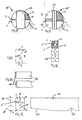
- FIG. I shows in the upper area an end view and a side view of a conical log section which has different diameters on the stick area and on the braid area.
- the lower part of FIG. I shows a side view and an end view of the starting material after the edge regions 8 of the individual elements 1-4 formed by longitudinal cuts made at right angles to one another have been processed.
- FIG. II shows an end view and a side view of the fully divided wooden beam 14 according to the invention, from which both the essentially central cavity 5 can be seen and the mutually reversed assignment of the individual elements 1-4.
- the individual elements 1-4 are each connected to one another in the region of the edge regions 8, for example by gluing, nailing or the like.
- IV and V each show end views of an output section 15 which has already been divided into individual elements 1-4 and in which one or more core planks or middle pieces 13 have been cut out. These can be used separately.
- Fig. VI the assignment of two individual elements 1 and 2 is shown in the front view, which are each provided with longitudinal slots 9, which prevent wood tension, and thus a distortion of the individual elements.
- VII shows cross-sectional views of wooden beams, e.g. similar to log building. It is possible to profile the wooden beam, for example in order to produce corresponding optical effects, or to seal one another.
- Fig. VIII an embodiment is shown, in which the front ends of the wooden beams 14 are each closed by means of a panel 10 in order to seal the cavity 5 both optically and from a technical point of view.
- the aperture 10 can be put on or inserted.
- Fig. IX of the wooden beam according to the invention shows that the individual elements 1-4 may have different side lengths, so that the cavity 5 is arranged off-center by a certain amount. In this way, recesses 17 or notches 16 can be worked out.
- the respective edge regions 8 of the individual elements 1-4 have different widths 18, 19.
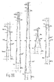
- X shows the possible variations of the method according to the invention.
- Fig. XI different possibilities are shown to profile the individual elements 1-4 at their edge areas 8, for example by gradations, tongue and groove configurations, by inserting a separate groove or the like, in order to create a connection between the individual elements 1-4 to improve.
- XIa shows the possibility of connecting additional attachments, for example boards or beams, to the wooden beam 14 according to the invention in order to increase its strength and / or cross section.
- Fig. XIb shows a composite of four half-wood-like individual pieces (21) with additional attachments.
- the invention is not limited to the exemplary embodiments shown; rather, there are various modification and modification possibilities for the person skilled in the art based on the basic principle, the outer areas of the log section forming the coreless interior area of the composite beam according to the invention, while the yield of the conical log path is used.
Landscapes
- Engineering & Computer Science (AREA)
- Life Sciences & Earth Sciences (AREA)
- Architecture (AREA)
- Wood Science & Technology (AREA)
- Manufacturing & Machinery (AREA)
- Forests & Forestry (AREA)
- Civil Engineering (AREA)
- Structural Engineering (AREA)
- Rod-Shaped Construction Members (AREA)
- Chemical And Physical Treatments For Wood And The Like (AREA)
- Veneer Processing And Manufacture Of Plywood (AREA)
Abstract
Description
Die Erfindung betrifft ein Verfahren zur Herstellung eines Holzbalkens, sowie einen Holzbalken in Verbundbauweise. Der Holzbalken besteht dabei aus mehreren, miteinander verbundenen, sich in Längsrichtung des Holzbalkens erstreckenden Einzelelementen, welche einen Hohlraum umschließen, wobei der Holzbalken im wesentlichen zueinander parallele, gegenüberliegende Seitenflächen aufweist.The invention relates to a method for producing a wooden beam, as well as a wooden beam in composite construction. The wooden beam consists of several interconnected individual elements that extend in the longitudinal direction of the wooden beam and enclose a cavity, the wooden beam having essentially mutually parallel, opposite side surfaces.
Aus dem Stand der Technik ist es bekannt, Holzbalken in Verbundbauweise herzustellen, wobei die Holzbalken oder Leimkonstruktionen einen zentrischen Hohlraum aufweisen. Bei derartigen bekannten Holzbalken werden üblicherweise vier Einzelelemente verwendet, welche einen dreieckförmigen Querschnitt aufweisen. Es sind auch Holzbalken bekannt, bei welchen jeweils Einzelelemente mit rechteckigem Querschnitt zur Verwendung kommen.It is known from the prior art to produce wooden beams in a composite construction, the wooden beams or glue structures having a central cavity. In such known wooden beams, four individual elements are usually used, which have a triangular cross section. Wooden beams are also known, in which individual elements with a rectangular cross section are used.
Bei den bekannten Holzbalken werden die Einzelelemente jeweils mit einem gleichartigen Querschnitt hergestellt, wobei hierfür ein relativ großer Verschnitt bei den als Ausgangsmaterial dienenden Rundholzabschnitten auftritt. Sofern im Stand der Technik die aus Rundholzabschnitten gefertigten Einzelelemente einen nicht gleichbleibenden Querschnitt aufweisen, verjüngt sich folglich auch der Querschnitt des fertigen Holzbalkens, so daß dieser, zur Erlangung paralleler Formen, nachfolgend noch in Einzelstücke unterteilt und bearbeitet werden muß.In the known wooden beams, the individual elements are each produced with a similar cross section, with a relatively large amount of waste the logs serving as the starting material occurs. If, in the prior art, the individual elements made from round wood sections have a non-constant cross-section, the cross-section of the finished wooden beam also tapers, so that, in order to obtain parallel shapes, it must subsequently be divided into individual pieces and processed.
Der Erfindung liegt die Aufgabe zugrunde, einen Holzbalken sowie ein Verfahren zu dessen Herstellung zu schaffen, bei welchem zur Erzeugung eines Holzbalkens mit einem gleichbleibenden Querschnitt der Verschnitt bzw. Materialverlust minimiert werden kann.The invention has for its object to provide a wooden beam and a method for its production, in which the waste or material loss can be minimized to produce a wooden beam with a constant cross-section.
Hinsichtlich des Holzbalkens wird die Erfindung dadurch gelöst, daß das Einzelelement an einer zum Hohlraum weisenden Seite zumindest zum Teil kegelstumpfartig ausgebildet ist.With regard to the wooden beam, the invention is achieved in that the individual element is at least partially frustoconical on a side facing the cavity.
Der erfindungsgemäße Holzbalken zeichnet sich durch eine Reihe erheblicher Vorteile aus. Da das Einzelelement pyramidenstumpfartig ausgeformt ist, ist es möglich, die natürlicherweise vorhandene Konizität eines Rundholzabschnittes zu verwenden, ohne daß eine Reduzierung auf eine gleichbleibende Querschnittsfläche des Ausgangsmaterials vor dessen Weiterverarbeitung erforderlich wäre. Die Menge des bei der Verarbeitung anfallenden Restmaterials kann somit erheblich reduziert werden, da die Einzelemente durch geeignetes Wenden oder entsprechendes Zuordnen zueinander zu einem Holzbalken zusammengesetzt werden können, dessen Querschnitt über seine Länge gleichbleibend ist, und welcher in etwa dem mittleren Durchmesser des verwendeten Rundholzabschnittes entspricht. Da die pyramidenstumpf artigen Teile die Bereich der Einzelelemente darstellen, welche gegeneinander in Anlage sind, ist eine innige Anlage der einzelnen Einzelelemente gewährleistet, wodurch ein hohes Maß an Festigkeit erzielbar ist.The wooden beam according to the invention is characterized by a number of considerable advantages. Since the individual element is shaped like a truncated pyramid, it is possible to use the naturally existing conicity of a log section without a reduction to a constant cross-sectional area of the starting material being necessary prior to its further processing. The amount of residual material arising during processing can thus be considerably reduced, since the individual elements can be put together to form a wooden beam by suitable turning or corresponding assignment, the cross-section of which is constant over its length and which corresponds approximately to the average diameter of the round timber section used . Because the truncated pyramid Like parts that represent the area of the individual elements, which are in contact with each other, an intimate contact of the individual individual elements is guaranteed, whereby a high degree of strength can be achieved.
In einer günstigen Ausgestaltung der Erfindung ist vorgesehen, daß vier Einzelelemente zu einem Holzbalken zusammengefügt werden. Diese Form weist den Vorteil auf, daß die vier Einzelelemente durch ihre jeweils zwei zueinander senkrechten Außenflächen die vier Ecken des quadratischen oder rechteckigen Hohlbalkens bilden.In a favorable embodiment of the invention it is provided that four individual elements are joined together to form a wooden beam. This shape has the advantage that the four individual elements form the four corners of the square or rectangular hollow beam due to their two mutually perpendicular outer surfaces.
Die zum Hohlraum weisende Seite des Einzelelements ist bevorzugterweise kegelstumpfartig, während die Randbereiche des Einzelelements, welche an ein benachbartes Einzelelement angrenzen, pyramidenstumpfartig ausgebildet sind. Erfindungsgemäß ist es möglich, rohe und konische (abholzige), aber vorzugsweise entrindete, Rundholzabschnitte oder Stämme zu entsprechenden Balken zu verarbeiten. Es ist lediglich nötig, die Randbereiche, welche zur Anlage des jeweils benachbarten Einzelelementes dienen sollen, pyramidenstumpfartig zu bearbeiten. Da diese Bereiche jedoch, bezogen auf den Gesamtumfang des runden Ausgangsmaterials, eine sehr geringe Fläche ausmachen, kann ein erheblicher Einsparungseffekt erreicht werden. Es ist möglich, das Ausgangsmaterial zu einem hohen Prozentsatz zu nutzen.The side of the individual element facing the cavity is preferably frustoconical, while the edge regions of the individual element which adjoin an adjacent individual element are truncated pyramid-like. According to the invention, it is possible to process raw and conical (woody), but preferably debarked, log sections or logs into corresponding beams. It is only necessary to process the edge areas, which are to serve for the abutment of the adjacent individual element, in the manner of a truncated pyramid. However, since these areas make up a very small area in relation to the total circumference of the round starting material, a considerable saving effect can be achieved. It is possible to use a high percentage of the raw material.
Um eine gleichbleibende Querschnittsfläche des Holzbalkens über dessen Länge sicherzustellen, und um eine saubere Verbindung der einzelnen Einzelelemente zu gewährleisten, erhalten die Einzelelemente jeweils, bezogen auf die pyramidenstumpfartigen Bereiche, angepaßte Schrägungswinkel.In order to ensure a constant cross-sectional area of the wooden beam over its length and to ensure a clean connection of the individual individual elements, the individual elements are each given an inclined angle with respect to the truncated pyramid-like areas.
In einer weiteren, besonders günstigen Ausgestaltung der Erfindung ist vorgesehen, daß das Einzelelement an der zum Hohlraum weisenden Seite mit zumindest einer Schlitzung versehen ist, diese begünstigt den Spannungsverlauf bei Holzfeuchteschwankungen.In a further, particularly advantageous embodiment of the invention, it is provided that the individual element is provided with at least one slit on the side facing the cavity, this favors the stress curve in the event of fluctuations in wood moisture.
Bei Holzbalken, welche stirnseitig sichtbar sind, ist es günstig, diese an der Stirnseite mit einer Blende zu versehen, welche aufgesetzt oder eingesetzt sein kann.In the case of wooden beams, which are visible on the end face, it is advantageous to provide them with a cover on the end face, which can be attached or inserted.
Weiterhin ist es erfindungsgemäß möglich, den Holzbalken an seiner Oberfläche zu profilieren oder in sonstiger Weise zu bearbeiten, so wie dies bei Vollmaterial-Holzbalken üblich ist.Furthermore, it is possible according to the invention to profile the wooden beam on its surface or to process it in some other way, as is customary with solid wooden beams.
In Abhängigkeit von dem gewünschten Querschnitt des fertigen Holzbalkens können die Einzelstücke auch unterschiedlich breite Außenflächen aufweisen, um beispielsweise den zentrischen Hohlraum außermittig anzuordnen, so daß an einer der Seiten des Holzbalkens weitere Bearbeitungen, beispielsweise Einkerbungen, Ausnehmungen o.ä., vorgesehen werden können.Depending on the desired cross-section of the finished wooden beam, the individual pieces can also have outer surfaces of different widths, for example to arrange the central cavity off-center, so that further processing, for example notches, recesses or the like, can be provided on one of the sides of the wooden beam.
In einer besonders günstigen Weiterentwicklung der Erfindung ist vorgesehen, daß die Randbereiche des Einzelelements, mit denen dieses mit einem benachbarten Einzelelement in Kontakt ist, strukturiert ausgebildet sind. Die Strukturierung kann in Form einer Nut-Federausgestaltung, oder in ähnlicher Weise, vorgenommen werden, um eine festere Verbindung zwischen den einzelnen Einzelelementen zu gewährleisten.In a particularly favorable further development of the invention, it is provided that the edge regions of the individual element with which it is in contact with an adjacent individual element are structured. The structuring can be carried out in the form of a tongue and groove configuration, or in a similar manner, in order to ensure a firmer connection between the individual individual elements.
Zusätzlich zu den Einzelelementen können an dem Holzbalken Anbauteile vorgesehen sein, beispielsweise zusätzliche Bretter, Verblendungen o.ä., und es ist auch vorgesehen, durch mehrere miteinander verbundene Holzbalken einen hohen Träger zu bilden.In addition to the individual elements, add-on parts can be provided on the wooden beam, for example additional boards, facings or the like, and it is also intended to form a high beam by several interconnected wooden beams.
Bezüglich des Verfahrens wird die Erfindung dadurch gelöst, daß ein konischer Rundholzabschnitt im wesentlichen in Längsrichtung zur Erzeugung der Einzelelemente geviertelt wird, wobei die Einzelelemente jeweils zwei zueinander rechtwinklige Flächen aufweisen, daß die Einzelelemente an den Randbereichen der ursprünglichen Außenseite pyramidenstumpfartig ausgeformt - und daß die Einzelelemente alternierend gewendet - und zu einem Holzbalken mit einem über die Länge gleichen Querschnitt miteinander verbunden werden. Das erfindungsgemäße Verfahren ist, bezogen auf die üblichen Verfahren zum Aufschneiden eines Rundholzabschnittes, einfach ausgebildet, es sind wenige Arbeitsschritte erforderlich und es fällt besonders wenig Verschnitt- oder Restmaterial an. Die Unterteilung des Rundholzabschnittes in die Einzelelemente kann durch Sägen, Messer oder Fräsen erfolgen.With regard to the method, the invention is achieved in that a conical round timber section is quartered substantially in the longitudinal direction to produce the individual elements, the individual elements each having two surfaces that are perpendicular to one another, that the individual elements are shaped like a truncated pyramid on the edge regions of the original outside - and that the individual elements alternately turned - and connected to a wooden beam with the same cross-section over the length. The method according to the invention is simple in relation to the customary methods for cutting open a log section, few work steps are required and there is particularly little waste or residual material. The log section can be subdivided into individual elements by sawing, knives or milling.
Weiterhin ist es erfindungsgemäß möglich, die Einzelelemente für einen Holzbalken aus verschiedenen Ausgangsabschnitten herzustellen, um beispielsweise unterschiedliche Konizitäten oder Krümmungen des Rundholzabschnittes berücksichtigen zu können.Furthermore, it is possible according to the invention to produce the individual elements for a wooden beam from different starting sections, for example in order to be able to take into account different conicity or curvatures of the round timber section.
In einer vorteilhaften Ausgestaltung des Verfahrens ist vorgesehen, daß in einem ersten Bearbeitungsschritt zunächst je zwei Einzelelemente zueinander ausgerichtet und in einem Bearbeitungsgang an ihren Randbereichen pyramidenstumpfförmig bearbeitet - und daß danach die Einzelelemente jeweils paarweise miteinander verbunden werden, und daß in einem zweiten Bearbeitungsschritt die beiden Paare von Einzelelementen an ihren Randbe reichen pyramidenstumpfförmig bearbeitet und zu dem Holzbalken miteinander verbunden werden. Diese Vorgehensweise gestattet es, im wesentlichen runde, konische Ausgangsmaterial zunächst durch Trennschnitte in die vier Einzelelemente zu unterteilen, ohne daß am Umfang des Ausgangsmaterials Arbeiten durchzuführen wären. Nach der Wendung zugehöriger Einzelelemente und deren Ausrichtung ist es nunmehr möglich, in einem Bearbeitungsgang, beispielsweise mittels eines breiteren Fräswerkzeugs o.ä., gleichzeitig die verbindenden Randbereiche der beiden Einzelelemente so zu bearbeiten, so daß diese insbesondere den gleichen Schrägungswinkel aufweisen. Zusätzlich ist es möglich, durch die Arbeitsbreite des Werkzeuges maßgenau die spätere Abmessung des Holzbalkens festzulegen. In analoger Weise erfolgt die nachfolgende gleichzeitige Bearbeitung der beiden Paare von Einzelelementen.In an advantageous embodiment of the method it is provided that, in a first processing step, two individual elements are initially aligned with one another and machined in the form of a truncated pyramid at their edge regions - and that the individual elements are then connected in pairs, and in a second processing step the two pairs of individual elements on their edge rich truncated pyramid shaped and connected to the wooden beam. This procedure allows essentially round, conical starting material to be divided into the four individual elements by separating cuts, without having to carry out any work on the circumference of the starting material. After the associated individual elements have been turned and aligned, it is now possible to simultaneously machine the connecting edge areas of the two individual elements in one machining step, for example by means of a wider milling tool or the like, so that they have in particular the same helix angle. In addition, it is possible to precisely determine the later dimensions of the wooden beam through the working width of the tool. The subsequent simultaneous processing of the two pairs of individual elements takes place in an analogous manner.
Alternativ dazu ist es erfindungsgemäß auch möglich, die Außenkontur des Rundholzabschnittes vor dem Trennen oder im Zuge der Trennung pyramidenstumpfförmig zu bearbeiten, oder die Halbhölzer vor (oder im Zuge) der Viertelung pyramidenstumpfartig zu profilieren..As an alternative to this, it is also possible according to the invention to process the outer contour of the round timber section in the form of a truncated pyramid before the separation or in the course of the separation, or to profile the half-timber in the manner of a truncated pyramid before (or in the course of) the quartering.
Sofern Ausgangsmaterialien verwendet werden, welche einen relativ großen Durchmesser aufweisen, welcher größer ist als der gewünschte Querschnitt des fertiggestellten Holzbalkens, oder wenn die Ecken des fertigen Holzbalkens nicht aus dem Kernbereich des Rundholzabschnittes bestehen sollen, dann kann bei der Trennung des Ausgangsmaterials zumindest eine Kernbohle oder ein Mittelstück ausgeschnitten und einer separaten Verwendung zugeführt werden.If starting materials are used that have a relatively large diameter, which is larger than the desired cross section of the finished wooden beam, or if the corners of the finished wooden beam should not consist of the core area of the round timber section, then at least one core plank or a middle piece is cut out and used separately.
Um erfindungsgemäß unterschiedliche Neigungswinkel des Ausgangsmaterials, d.h. der runden - kegelstumpfförmigen Rundhölzer, berücksichtigen bzw. nutzen zu können, ist es günstig, wenn der Rundholzabschnitt, oder die getrennten Einzelstücke, zur Bestimmung des Winkels des Pyramidenstumpfs, und/oder zur Ermittlung der Bearbeitung der Ränder, vermessen werden.According to the invention, different angles of inclination of the starting material, i.e. of the round - frustoconical logs, it can be advantageous if the log section or the separate individual pieces are measured to determine the angle of the truncated pyramid and / or to determine the machining of the edges.
Im folgenden wird die Erfindung anhand von Ausführungsbeispielen in Verbindung mit der Zeichnung beschrieben. Dabei zeigt:
- Fig. I eine stirnseitige Ansicht sowie jeweils eine Seitenansicht eines Ausgangs-Rundholzabschnittes im ursprünglichen Zustand und nach Unterteilung in vier Einzelstücke und Bearbeitung der Außenkonturen,
- Fig. II eine Stirnansicht sowie eine Seitenansicht eines fertiggestellten erfindungsgemäßen Holzbalkens,
- Fig. III eine stirnseitige Ansicht sowie eine Seitenansicht eines in vier Einzelelemente unterteilten, am Außenumfang nicht bearbeiteten Rundholzabschnittes,
- Fig. IV eine Stirnansicht eines Ausgangsabschnittes, nach Unterteilung in Einzelelemente und eines Mittelstückes,
- Fig. V eine stirnseitige Ansicht, ähnlich Fig. IV, bei welcher aus dem Ausgangsabschnitt mehrere Kernbohlen ausgeschnitten wurden,
- Fig. VI eine stirnseitige Ansicht zweier zugeordneter Einzelelemente mit jeweils einer Längsschlitzung,
- Fig. VII stirnseitige Ansicht eines erfindungsgemäßen Holzbalkens, welcher aus einer größeren Anzahl von Einzelelementen zusammengesetzt ist und an einer Fläche eine Außenstrukturierung aufweist,
- Fig.VIII eine Seitenansicht zweier Ausführungsbeispiele des erfindungsgemäßen Holzbalkens mit stirnseitigen Blenden,
- Fig. IX eine Stirnansicht und eine Seitenansicht eines erfindungsgemäßen Holzbalkens, welcher über die Länge unterschiedliche Querschnittsstrukturierungen aufweist,
- Fig. X stirnseitige Ansichten eines erfindungsgemäßen Holzbalkens, sowie zweier durch unterschiedliche Schnitte unterteilter Ausgangsabschnitte,
- Fig. XI eine Stirnansicht eines weiteren Ausführungsbeispiels des erfindungsgemäßen Holzbalkens,
- Fig. XIa Stirnansichten weiterer Ausführungsbeispiele des erfindungsgemäßen Holzbalkens mit aufgesetzten Anbauteilen,
- Fig. XIb Stirnansicht eines erfindungsgemäßen Holzbalkens mit u.a. vier halbholzähnlichen Einzelstücken,
- Fig. XII Seitenansichten unterschiedlich konischer Ausgangs-Rundholzabschnitten,
- Fig.XIII Stirnansichten sowie Seitenansichten unterschiedlicher Arbeitsstufen bei der Herstellung eines erfindungsgemäßen Holzbalkens,
- Fig.XIV Stirnansichten sowie Seitenansichten von halbholzförmigen Einzelstücken, die pyramidenförmig profiliert und zu Viertelstücken getrennt sind.
- Fig. XV Stirnansicht von übereinander gesetzten und miteinander verbundenen Einzelbalken zu einem Träger mit hohem Querschnitt.
- I is a front view and a side view of an initial log section in the original state and after subdivision into four individual pieces and processing of the outer contours,
- II is a front view and a side view of a finished wooden beam according to the invention,
- III an end view and a side view of a round wood section divided into four individual elements and not machined on the outer circumference,
- IV is an end view of an exit section, after subdivision into individual elements and a center piece,
- V is an end view, similar to FIG. IV, in which several core planks have been cut out from the starting section,
- VI is an end view of two associated individual elements, each with a longitudinal slot,
- VII frontal view of a wooden beam according to the invention, which is composed of a larger number of individual elements and has an outer structure on one surface,
- VIII a side view of two exemplary embodiments of the wooden beam according to the invention with front panels,
- IX is an end view and a side view of a wooden beam according to the invention, which has different cross-sectional structures over the length,
- X front views of a wooden beam according to the invention, as well as two starting sections divided by different cuts,
- XI is an end view of a further embodiment of the wooden beam according to the invention,
- XIa end views of further embodiments of the wooden beam according to the invention with attached parts,
- XIb end view of a wooden beam according to the invention with, inter alia, four half-wood-like individual pieces,
- XII side views of different conical starting log sections,
- XIII end views and side views of different work stages in the manufacture of a wooden beam according to the invention,
- Fig.XIV end views and side views of half-wood-shaped individual pieces, which are profiled pyramid-shaped and separated into quarter pieces.
- XV end view of individual beams placed one above the other and connected to one another to form a support with a high cross section.
Die Fig. I zeigt im oberen Bereich eine Stirnansicht sowie eine Seitenansicht eines konischen Rundholzabschnittes, welcher unterschiedliche Durchmesser am Stockbereich und am Zopfbereich aufweist. Der untere Teil der Fig. I zeigt eine Seitenansicht sowie eine stirnseitige Ansicht des Ausgangsmaterials, nachdem jeweils die Randbereiche 8 der durch rechtwinklig zueinander erfolgten Längsschnitte gebildeten Einzelelemente 1-4 bearbeitet wurden.I shows in the upper area an end view and a side view of a conical log section which has different diameters on the stick area and on the braid area. The lower part of FIG. I shows a side view and an end view of the starting material after the edge regions 8 of the individual elements 1-4 formed by longitudinal cuts made at right angles to one another have been processed.
Die Fig. II zeigt eine stirnseitige Ansicht sowie eine Seitenansicht des fertiggesteilten erfindungsgemäßen Holzbalkens 14, aus welcher sowohl der im wesentlichen zentrische Hohlraum 5 zu ersehen ist, als auch die jeweils wechselseitig gewendete Zuordnung der Einzelelemente 1-4. Wie weiterhin aus Fig. II erkennbar ist, sind die Einzelelemente 1-4 jeweils im Bereich der Randbereiche 8 miteinander verbunden, beispielsweise durch Verleimen, Nageln o.ä.II shows an end view and a side view of the fully divided
Um die Unterteilung in die Einzelelemente 1-4 und deren Zuordnung zu einem Holzbalken 14 gleichbleibenden Querschnitts vornehmen zu können, ist eine Vermessung des Ausgangsbalkens 15 vorteilhaft, so wie dies in Fig. III und XII dargestellt ist. Wie sich aus Fig. XII ergibt, ist es möglich, ausgehend von dem mittleren Durchmesser des Ausgangsabschnittes 15, den maximal möglichen Querschnitt des fertigen Holzbalkens 14 zu bestimmen und die dementsprechend jeweiligen Abschrägungen des pyramidenstumpfartigen Randbereichs 8 festzulegen.In order to be able to subdivide into the individual elements 1-4 and to assign them to a
Die Fig. IV und V zeigen jeweils Stirnansichten eines bereits in Einzelelemente 1-4 unterteilten Ausgangsabschnittes 15, bei welchem eine oder mehrere Kernbohlen oder Mittelstücke 13 ausgeschnitten wurden. Diese können einer separaten Verwendung zugeführt werden.IV and V each show end views of an
In Fig. VI ist in der stirnseitigen Ansicht die Zuordnung zweier Einzelelemente 1 und 2 dargestellt, welche jeweils mit Längsschlitzungen 9 versehen sind, welche Holzspannungen, und damit einem Verzug der Einzelelemente, vorbeugen.In Fig. VI, the assignment of two
Erfindungsgemäß ist es möglich, beliebige Variationen zu den in den Fig. IV und V gezeigten Anordnungen auszubilden.According to the invention, it is possible to design any variations to the arrangements shown in FIGS. IV and V.
Um erfindungsgemäß einen Holzbalken - ohne Ausschuß von Viertelstücken - erzeugen zu können, um also das Ausgangsmaterial möglichst vollständig zu nutzen, kann es sich als günstig erweisen, das Ausgangsmaterial, wie in Fig. III dargestellt, zunächst im rohen Zustand zu halbieren bzw. zu vierteln, und die dabei erhaltenen Einzelelemente nachträglich zu vermessen, um festzustellen, ob die jeweiligen Werte 0,5 F1 und 0,5 F2 noch eine ausreichende Fügefläche ermöglichen, oder ob das eine oder andere Einzelstück in die nächstniedrige Querschnittsklasse des Verbundbalkens einzubauen ist.In order to be able to produce a wooden beam according to the invention - without rejecting quarter pieces, so that the raw material is used as completely as possible, it can prove to be advantageous to first halve or quarter the raw material in raw form, as shown in Fig. III , and subsequently measure the individual elements obtained in order to determine whether the respective values 0.5 F1 and 0.5 F2 still allow a sufficient joining area, or whether one or the other individual piece is to be installed in the next lower cross-sectional class of the composite beam.
Die Fig. VII zeigt Querschnittsansichten von Holzbalken, z.B. ähnlich des Blockhausbaues. Es ist hierbei möglich, den Holzbalken zu profilieren, beispielsweise um entsprechende optische Effekte hervorzurufen, oder gegenseitig abzudichten.VII shows cross-sectional views of wooden beams, e.g. similar to log building. It is possible to profile the wooden beam, for example in order to produce corresponding optical effects, or to seal one another.
In Fig. VIII ist ein Ausführungsbeispiel gezeigt, bei welchem die stirnseitigen Enden der Holzbalken 14 jeweils mittels einer Blende 10 verschlossen sind, um den Hohlraum 5 sowohl optisch als auch in technischer Hinsicht abzudichten. Die Blende 10 kann aufgesetzt oder eingesetzt sein.In Fig. VIII an embodiment is shown, in which the front ends of the
Das in Fig. IX gezeigte Ausführungsbeispiel des erfindungsgemäßen Holzbalkens zeigt, daß die Einzelelemente 1-4 unterschiedliche Seitenlängen aufweisen können, so daß der Hohlraum 5 um einen bestimmten Betrag außermittig angeordnet ist. Es können hierdurch Ausnehmungen 17 oder Einkerbungen 16 ausgearbeitet werden. Die jeweiligen Randbereiche 8 der Einzelelemente 1-4 weisen dabei unterschiedliche Breiten 18, 19 auf.The embodiment shown in Fig. IX of the wooden beam according to the invention shows that the individual elements 1-4 may have different side lengths, so that the
Die Fig. X zeigt, welche Variationsmöglichkeiten das erfindungsgemäße Verfahren bietet. Es ist möglich, zur Abdeckung der geforderten unterschiedlichen Querschnittsdimensionierungen der Holzbalken die Aufteilung des Ausgangsabschnittes 15 in unterschiedlich dimensionierte Einzelelemente 1-4 vorzunehmen, um auf diese Weise die verschiedensten Querschnittsprofile erzeugen zu können. Dabei ist es insbesondere wichtig, daß die Einzelelemente 1-4 jeweils nicht aus demselben Rundholzabschnitt 15 stammen müssen. Es ist deshalb bei dem Ausgangsbalken 15 nicht erforderlich, daß dieser jeweils symmetrisch in die Einzelelemente 1-4 aufgeteilt wird.X shows the possible variations of the method according to the invention. To cover the required different cross-sectional dimensions of the wooden beams, it is possible to divide the
In Fig. XI sind verschiedene Möglichkeiten dargestellt, die Einzelelemente 1-4 an ihren Randbereichen 8 zu profilieren, beispielsweise durch Abstufungen, Nut- und Federausbildungen, durch das Einlegen einer separaten Nut o.ä., um eine Verbindung zwischen den Einzelelementen 1-4 zu verbessern.In Fig. XI different possibilities are shown to profile the individual elements 1-4 at their edge areas 8, for example by gradations, tongue and groove configurations, by inserting a separate groove or the like, in order to create a connection between the individual elements 1-4 to improve.
Die Fig. XIa zeigt die Möglichkeit, zusätzliche Anbauteile, beispielsweise Bretter oder Balken mit dem erfindungsgemäßen Holzbalken 14 zu verbinden, um dessen Festigkeit und/oder Querschnitt zu vergrößern.XIa shows the possibility of connecting additional attachments, for example boards or beams, to the
Die Fig. XIb zeigt einen Verbund aus vier halbholzähnlichen Einzelstücken (21) mit zusätzlichen Anbauteilen.Fig. XIb shows a composite of four half-wood-like individual pieces (21) with additional attachments.
Die Erfindung ist nicht auf die gezeigten Ausführungsbeispiele beschränkt, es ergeben sich für den Fachmann vielmehr vielfältige Abwandlungs- und Modifikationsmöglichkeiten nach dem Grundprinzip, wobei jeweils Außenbereiche des Rundholzabschnittes den kernlosen Innenbereich des erfindungsgemäßen Verbundbalkens, bei Ausbeutenutzung des konischen Rundholzverlaufes bilden.The invention is not limited to the exemplary embodiments shown; rather, there are various modification and modification possibilities for the person skilled in the art based on the basic principle, the outer areas of the log section forming the coreless interior area of the composite beam according to the invention, while the yield of the conical log path is used.
Claims (20)
Applications Claiming Priority (2)
| Application Number | Priority Date | Filing Date | Title |
|---|---|---|---|
| DE8903670 | 1989-03-23 | ||
| DE8903670U | 1989-03-23 |
Publications (3)
| Publication Number | Publication Date |
|---|---|
| EP0388507A2 true EP0388507A2 (en) | 1990-09-26 |
| EP0388507A3 EP0388507A3 (en) | 1991-07-10 |
| EP0388507B1 EP0388507B1 (en) | 1995-06-28 |
Family
ID=6837488
Family Applications (1)
| Application Number | Title | Priority Date | Filing Date |
|---|---|---|---|
| EP89112260A Expired - Lifetime EP0388507B1 (en) | 1989-03-23 | 1989-07-05 | Wooden beam and method for manufacturing the same |
Country Status (4)
| Country | Link |
|---|---|
| EP (1) | EP0388507B1 (en) |
| AT (1) | ATE124313T1 (en) |
| DE (1) | DE58909326D1 (en) |
| ES (1) | ES2076176T3 (en) |
Cited By (11)
| Publication number | Priority date | Publication date | Assignee | Title |
|---|---|---|---|---|
| WO1992008587A1 (en) * | 1990-11-08 | 1992-05-29 | Träform Ab | A means for sawing elongate units from a tree-trunk |
| WO1992016339A1 (en) * | 1991-03-19 | 1992-10-01 | Martin Wiklund | Process for sawing logs |
| EP0518246A2 (en) * | 1991-06-14 | 1992-12-16 | Berthold Fries | Method for production of wooden hollow beams and forms of this beam obtained by this method |
| EP0549744A1 (en) * | 1991-07-03 | 1993-07-07 | Peter Sing | Method of converting logs and resultant product. |
| EP0673732A1 (en) * | 1993-07-12 | 1995-09-27 | Ibiden Co, Ltd. | Laminated lumber, method for producing laminated lumber, and laminated lumber producing device |
| WO1997009492A2 (en) * | 1995-09-06 | 1997-03-13 | Dragica Graf | Half-timbering system and framework elements and method of producing a framework element |
| USRE36153E (en) * | 1992-09-24 | 1999-03-23 | Sing; Peter | Converted log structural products and method |
| US6032434A (en) * | 1995-09-06 | 2000-03-07 | Dragica Graf | Half-timber frame and half-timber compartment element |
| WO2000045006A1 (en) * | 1999-01-28 | 2000-08-03 | Karlstroem Johan Tore | Method and arrangement for wood studs |
| WO2002010531A1 (en) * | 2000-07-27 | 2002-02-07 | Karlstroem Johan Tore | Stud arrangement and method |
| US6446412B2 (en) * | 2000-01-27 | 2002-09-10 | Mathis Tech Inc. | Glulam wood beams and method of making same |
Families Citing this family (1)
| Publication number | Priority date | Publication date | Assignee | Title |
|---|---|---|---|---|
| RU2461687C1 (en) * | 2011-01-18 | 2012-09-20 | Василий Николаевич Парфенов | Wooden precast unit and cladding structure of wood structure assembled from wooden precast units |
Citations (8)
| Publication number | Priority date | Publication date | Assignee | Title |
|---|---|---|---|---|
| SE108237C1 (en) * | 1941-12-17 | 1943-08-17 | ||
| SE115667C1 (en) * | 1943-02-17 | 1946-01-15 | ||
| FR962589A (en) * | 1950-06-16 | |||
| DE1484346A1 (en) * | 1964-03-10 | 1968-11-28 | Wilhelm Poppensieker | Process for the production of wooden beams |
| DE1453014A1 (en) * | 1962-10-19 | 1968-12-19 | Ask Jonas Waldemar | Method and device for the production of rectangular boards from boards with inclined surfaces |
| NL8004909A (en) * | 1980-08-29 | 1982-04-01 | Petrus Johannus Maria Meegdes | Glued hollow wooden structure - comprises strips with teeth at gluing points, without nails |
| FR2512729A1 (en) * | 1981-09-15 | 1983-03-18 | Chambon Alain | Method of making large wooden beam - has small octagonal shaped logs cut and re-assembled to cruciform section |
| EP0167013A2 (en) * | 1984-07-05 | 1986-01-08 | Schauman Wood Oy | A method of cutting round timber |
-
1989
- 1989-07-05 AT AT89112260T patent/ATE124313T1/en not_active IP Right Cessation
- 1989-07-05 EP EP89112260A patent/EP0388507B1/en not_active Expired - Lifetime
- 1989-07-05 DE DE58909326T patent/DE58909326D1/en not_active Expired - Fee Related
- 1989-07-05 ES ES89112260T patent/ES2076176T3/en not_active Expired - Fee Related
Patent Citations (8)
| Publication number | Priority date | Publication date | Assignee | Title |
|---|---|---|---|---|
| FR962589A (en) * | 1950-06-16 | |||
| SE108237C1 (en) * | 1941-12-17 | 1943-08-17 | ||
| SE115667C1 (en) * | 1943-02-17 | 1946-01-15 | ||
| DE1453014A1 (en) * | 1962-10-19 | 1968-12-19 | Ask Jonas Waldemar | Method and device for the production of rectangular boards from boards with inclined surfaces |
| DE1484346A1 (en) * | 1964-03-10 | 1968-11-28 | Wilhelm Poppensieker | Process for the production of wooden beams |
| NL8004909A (en) * | 1980-08-29 | 1982-04-01 | Petrus Johannus Maria Meegdes | Glued hollow wooden structure - comprises strips with teeth at gluing points, without nails |
| FR2512729A1 (en) * | 1981-09-15 | 1983-03-18 | Chambon Alain | Method of making large wooden beam - has small octagonal shaped logs cut and re-assembled to cruciform section |
| EP0167013A2 (en) * | 1984-07-05 | 1986-01-08 | Schauman Wood Oy | A method of cutting round timber |
Cited By (20)
| Publication number | Priority date | Publication date | Assignee | Title |
|---|---|---|---|---|
| AU646707B2 (en) * | 1990-11-08 | 1994-03-03 | Traform Ab | An installation for producing a timber product |
| WO1992008587A1 (en) * | 1990-11-08 | 1992-05-29 | Träform Ab | A means for sawing elongate units from a tree-trunk |
| WO1992016339A1 (en) * | 1991-03-19 | 1992-10-01 | Martin Wiklund | Process for sawing logs |
| US6286571B1 (en) | 1991-03-19 | 2001-09-11 | Martin Wiklund | Process for sawing logs |
| EP0518246A2 (en) * | 1991-06-14 | 1992-12-16 | Berthold Fries | Method for production of wooden hollow beams and forms of this beam obtained by this method |
| EP0518246A3 (en) * | 1991-06-14 | 1993-05-19 | Berthold Fries | Method for production of wooden hollow beams and forms of this beam obtained by this method |
| EP0549744A4 (en) * | 1991-07-03 | 1993-12-29 | Peter Sing | Method of converting logs and resultant product |
| USRE35327E (en) * | 1991-07-03 | 1996-09-10 | Sing; Peter | Method of converting logs and resultant product |
| EP0549744A1 (en) * | 1991-07-03 | 1993-07-07 | Peter Sing | Method of converting logs and resultant product. |
| USRE36153E (en) * | 1992-09-24 | 1999-03-23 | Sing; Peter | Converted log structural products and method |
| EP0673732A4 (en) * | 1993-07-12 | 1997-04-23 | Ibiden Co Ltd | Laminated lumber, method for producing laminated lumber, and laminated lumber producing device. |
| EP0673732A1 (en) * | 1993-07-12 | 1995-09-27 | Ibiden Co, Ltd. | Laminated lumber, method for producing laminated lumber, and laminated lumber producing device |
| US6032434A (en) * | 1995-09-06 | 2000-03-07 | Dragica Graf | Half-timber frame and half-timber compartment element |
| WO1997009492A3 (en) * | 1995-09-06 | 1997-05-22 | Dragica Graf | Half-timbering system and framework elements and method of producing a framework element |
| WO1997009492A2 (en) * | 1995-09-06 | 1997-03-13 | Dragica Graf | Half-timbering system and framework elements and method of producing a framework element |
| WO2000045006A1 (en) * | 1999-01-28 | 2000-08-03 | Karlstroem Johan Tore | Method and arrangement for wood studs |
| US6761009B1 (en) | 1999-01-28 | 2004-07-13 | Karlstroem Johan Tore | Method and arrangement for wood studs |
| US6446412B2 (en) * | 2000-01-27 | 2002-09-10 | Mathis Tech Inc. | Glulam wood beams and method of making same |
| WO2002010531A1 (en) * | 2000-07-27 | 2002-02-07 | Karlstroem Johan Tore | Stud arrangement and method |
| US7225594B2 (en) | 2000-07-27 | 2007-06-05 | Karlstroem Johan Tore | Stud system and methods related thereto |
Also Published As
| Publication number | Publication date |
|---|---|
| EP0388507B1 (en) | 1995-06-28 |
| DE58909326D1 (en) | 1995-08-03 |
| ATE124313T1 (en) | 1995-07-15 |
| EP0388507A3 (en) | 1991-07-10 |
| ES2076176T3 (en) | 1995-11-01 |
Similar Documents
| Publication | Publication Date | Title |
|---|---|---|
| EP0107690B1 (en) | Method and device for transforming billets into construction wood | |
| EP0388507B1 (en) | Wooden beam and method for manufacturing the same | |
| EP0518246B1 (en) | Method for production of wooden hollow beams and forms of this beam obtained by this method | |
| DE2947611A1 (en) | METHOD FOR PRODUCING BOARD SLATS FROM ROD | |
| DE69223596T2 (en) | Composite with diagonal wood grain | |
| DE2159337A1 (en) | METHOD AND DEVICE FOR MANUFACTURING SAW WOOD | |
| EP2384383B1 (en) | Method for producing a glulam slat girder and glulam slat girder | |
| DE857139C (en) | Lattice girders made of wooden belts and metal struts and process for its manufacture | |
| EP1721714B1 (en) | Composite wooden beam | |
| EP0426015B1 (en) | Multiply wood products such as beams, planks and glued boards and process for their manufacture | |
| DE69517046T2 (en) | CONNECTING DESIGN FOR WOODEN ELEMENTS | |
| DE3623235C2 (en) | ||
| EP0663272B1 (en) | Method for subdividing logs in pieces that are machined on all sides | |
| EP0027488B1 (en) | Wood-construction element consisting of a lateral section of round wood milled essentially trapezoid cross-sectionally, and sawn timber produced therefrom | |
| AT398220B (en) | WOODEN ELEMENT AND METHOD FOR PRODUCING WOODEN ELEMENTS | |
| DE2902222C2 (en) | Process for the production of solid wood profiles | |
| DE8912321U1 (en) | Composite wooden beams | |
| EP0038041A2 (en) | Rectangular wood panel and method of its manufacture | |
| DE2615745C3 (en) | Method for producing squared timber from round timber sections | |
| AT397489B (en) | Glued laminated board with a lamella thickness of 45 mm | |
| DE9107371U1 (en) | Wooden beams | |
| DE3913160A1 (en) | Method of producing wood panels - by using basic board tongued or grooved and cut into lengths at angle to its long sides | |
| DE10161024A1 (en) | Laminar beam of trapezoid-section strips has identical triangular strips placed asymmetrically, with no common cut point | |
| DE69929884T2 (en) | METHOD FOR DISTRIBUTING A TREE TRUNK AND WOODEN UNIT | |
| WO1988004531A1 (en) | Process for manufacturing panels of different thickness made of wood or wood substitutes |
Legal Events
| Date | Code | Title | Description |
|---|---|---|---|
| PUAI | Public reference made under article 153(3) epc to a published international application that has entered the european phase |
Free format text: ORIGINAL CODE: 0009012 |
|
| AK | Designated contracting states |
Kind code of ref document: A2 Designated state(s): AT BE CH DE ES FR GB GR IT LI LU NL SE |
|
| PUAL | Search report despatched |
Free format text: ORIGINAL CODE: 0009013 |
|
| AK | Designated contracting states |
Kind code of ref document: A3 Designated state(s): AT BE CH DE ES FR GB GR IT LI LU NL SE |
|
| 17P | Request for examination filed |
Effective date: 19911221 |
|
| 17Q | First examination report despatched |
Effective date: 19930303 |
|
| GRAA | (expected) grant |
Free format text: ORIGINAL CODE: 0009210 |
|
| AK | Designated contracting states |
Kind code of ref document: B1 Designated state(s): AT BE CH DE ES FR GB GR IT LI LU NL SE |
|
| PG25 | Lapsed in a contracting state [announced via postgrant information from national office to epo] |
Ref country code: GR Free format text: LAPSE BECAUSE OF FAILURE TO SUBMIT A TRANSLATION OF THE DESCRIPTION OR TO PAY THE FEE WITHIN THE PRESCRIBED TIME-LIMIT Effective date: 19950628 |
|
| REF | Corresponds to: |
Ref document number: 124313 Country of ref document: AT Date of ref document: 19950715 Kind code of ref document: T |
|
| ITF | It: translation for a ep patent filed | ||
| PG25 | Lapsed in a contracting state [announced via postgrant information from national office to epo] |
Ref country code: LU Free format text: LAPSE BECAUSE OF NON-PAYMENT OF DUE FEES Effective date: 19950731 |
|
| REF | Corresponds to: |
Ref document number: 58909326 Country of ref document: DE Date of ref document: 19950803 |
|
| GBT | Gb: translation of ep patent filed (gb section 77(6)(a)/1977) |
Effective date: 19950814 |
|
| ET | Fr: translation filed | ||
| REG | Reference to a national code |
Ref country code: ES Ref legal event code: FG2A Ref document number: 2076176 Country of ref document: ES Kind code of ref document: T3 |
|
| PLBI | Opposition filed |
Free format text: ORIGINAL CODE: 0009260 |
|
| PLAV | Examination of admissibility of opposition |
Free format text: ORIGINAL CODE: EPIDOS OPEX |
|
| 26 | Opposition filed |
Opponent name: AUERBACH WERKZEUGMASCHINEN GMBH Effective date: 19960224 |
|
| PLAV | Examination of admissibility of opposition |
Free format text: ORIGINAL CODE: EPIDOS OPEX |
|
| PLBF | Reply of patent proprietor to notice(s) of opposition |
Free format text: ORIGINAL CODE: EPIDOS OBSO |
|
| NLR1 | Nl: opposition has been filed with the epo |
Opponent name: AUERBACH WERKZEUGMASCHINEN GMBH |
|
| PLBF | Reply of patent proprietor to notice(s) of opposition |
Free format text: ORIGINAL CODE: EPIDOS OBSO |
|
| PLBF | Reply of patent proprietor to notice(s) of opposition |
Free format text: ORIGINAL CODE: EPIDOS OBSO |
|
| PGFP | Annual fee paid to national office [announced via postgrant information from national office to epo] |
Ref country code: SE Payment date: 19970129 Year of fee payment: 8 Ref country code: ES Payment date: 19970129 Year of fee payment: 8 Ref country code: AT Payment date: 19970129 Year of fee payment: 8 |
|
| PGFP | Annual fee paid to national office [announced via postgrant information from national office to epo] |
Ref country code: NL Payment date: 19970131 Year of fee payment: 8 |
|
| PGFP | Annual fee paid to national office [announced via postgrant information from national office to epo] |
Ref country code: CH Payment date: 19970203 Year of fee payment: 8 |
|
| PGFP | Annual fee paid to national office [announced via postgrant information from national office to epo] |
Ref country code: BE Payment date: 19970214 Year of fee payment: 8 |
|
| PLBO | Opposition rejected |
Free format text: ORIGINAL CODE: EPIDOS REJO |
|
| PLBN | Opposition rejected |
Free format text: ORIGINAL CODE: 0009273 |
|
| STAA | Information on the status of an ep patent application or granted ep patent |
Free format text: STATUS: OPPOSITION REJECTED |
|
| PG25 | Lapsed in a contracting state [announced via postgrant information from national office to epo] |
Ref country code: AT Free format text: LAPSE BECAUSE OF NON-PAYMENT OF DUE FEES Effective date: 19970705 |
|
| PG25 | Lapsed in a contracting state [announced via postgrant information from national office to epo] |
Ref country code: SE Effective date: 19970706 |
|
| PG25 | Lapsed in a contracting state [announced via postgrant information from national office to epo] |
Ref country code: ES Free format text: LAPSE BECAUSE OF THE APPLICANT RENOUNCES Effective date: 19970707 |
|
| 27O | Opposition rejected |
Effective date: 19970306 |
|
| PG25 | Lapsed in a contracting state [announced via postgrant information from national office to epo] |
Ref country code: LI Free format text: LAPSE BECAUSE OF NON-PAYMENT OF DUE FEES Effective date: 19970731 Ref country code: CH Free format text: LAPSE BECAUSE OF NON-PAYMENT OF DUE FEES Effective date: 19970731 Ref country code: BE Free format text: LAPSE BECAUSE OF NON-PAYMENT OF DUE FEES Effective date: 19970731 |
|
| NLR2 | Nl: decision of opposition | ||
| PGFP | Annual fee paid to national office [announced via postgrant information from national office to epo] |
Ref country code: GB Payment date: 19971217 Year of fee payment: 9 |
|
| PGFP | Annual fee paid to national office [announced via postgrant information from national office to epo] |
Ref country code: FR Payment date: 19980129 Year of fee payment: 9 |
|
| PGFP | Annual fee paid to national office [announced via postgrant information from national office to epo] |
Ref country code: DE Payment date: 19980130 Year of fee payment: 9 |
|
| BERE | Be: lapsed |
Owner name: FRIES BERTHOLD Effective date: 19970731 |
|
| PG25 | Lapsed in a contracting state [announced via postgrant information from national office to epo] |
Ref country code: NL Free format text: LAPSE BECAUSE OF NON-PAYMENT OF DUE FEES Effective date: 19980201 |
|
| REG | Reference to a national code |
Ref country code: CH Ref legal event code: PL |
|
| NLV4 | Nl: lapsed or anulled due to non-payment of the annual fee |
Effective date: 19980201 |
|
| EUG | Se: european patent has lapsed |
Ref document number: 89112260.8 |
|
| PG25 | Lapsed in a contracting state [announced via postgrant information from national office to epo] |
Ref country code: GB Free format text: LAPSE BECAUSE OF NON-PAYMENT OF DUE FEES Effective date: 19980705 |
|
| GBPC | Gb: european patent ceased through non-payment of renewal fee |
Effective date: 19980705 |
|
| PG25 | Lapsed in a contracting state [announced via postgrant information from national office to epo] |
Ref country code: FR Free format text: LAPSE BECAUSE OF NON-PAYMENT OF DUE FEES Effective date: 19990331 |
|
| PG25 | Lapsed in a contracting state [announced via postgrant information from national office to epo] |
Ref country code: DE Free format text: LAPSE BECAUSE OF NON-PAYMENT OF DUE FEES Effective date: 19990501 |
|
| REG | Reference to a national code |
Ref country code: FR Ref legal event code: ST |
|
| REG | Reference to a national code |
Ref country code: ES Ref legal event code: FD2A Effective date: 20001102 |
|
| PG25 | Lapsed in a contracting state [announced via postgrant information from national office to epo] |
Ref country code: IT Free format text: LAPSE BECAUSE OF NON-PAYMENT OF DUE FEES Effective date: 20050705 |