EP0383987B1 - Antriebsmechanismus für Überfahrbrücken für Rampen - Google Patents
Antriebsmechanismus für Überfahrbrücken für Rampen Download PDFInfo
- Publication number
- EP0383987B1 EP0383987B1 EP89103325A EP89103325A EP0383987B1 EP 0383987 B1 EP0383987 B1 EP 0383987B1 EP 89103325 A EP89103325 A EP 89103325A EP 89103325 A EP89103325 A EP 89103325A EP 0383987 B1 EP0383987 B1 EP 0383987B1
- Authority
- EP
- European Patent Office
- Prior art keywords
- bridge
- driving mechanism
- rolling element
- mechanism according
- loading bridge
- Prior art date
- Legal status (The legal status is an assumption and is not a legal conclusion. Google has not performed a legal analysis and makes no representation as to the accuracy of the status listed.)
- Expired - Lifetime
Links
- 238000005096 rolling process Methods 0.000 claims abstract description 23
- 230000007246 mechanism Effects 0.000 claims description 28
- 229910000831 Steel Inorganic materials 0.000 claims description 10
- 239000010959 steel Substances 0.000 claims description 10
- 238000000034 method Methods 0.000 description 4
- 238000010276 construction Methods 0.000 description 2
- 238000009826 distribution Methods 0.000 description 2
- 238000004804 winding Methods 0.000 description 2
- 230000002411 adverse Effects 0.000 description 1
- 230000000694 effects Effects 0.000 description 1
- 230000002349 favourable effect Effects 0.000 description 1
- 238000004519 manufacturing process Methods 0.000 description 1
- 238000004904 shortening Methods 0.000 description 1
Images
Classifications
-
- B—PERFORMING OPERATIONS; TRANSPORTING
- B65—CONVEYING; PACKING; STORING; HANDLING THIN OR FILAMENTARY MATERIAL
- B65G—TRANSPORT OR STORAGE DEVICES, e.g. CONVEYORS FOR LOADING OR TIPPING, SHOP CONVEYOR SYSTEMS OR PNEUMATIC TUBE CONVEYORS
- B65G69/00—Auxiliary measures taken, or devices used, in connection with loading or unloading
- B65G69/28—Loading ramps; Loading docks
- B65G69/2805—Loading ramps; Loading docks permanently installed on the dock
- B65G69/2811—Loading ramps; Loading docks permanently installed on the dock pivoting ramps
- B65G69/2835—Loading ramps; Loading docks permanently installed on the dock pivoting ramps with spring-operated means
- B65G69/2841—Loading ramps; Loading docks permanently installed on the dock pivoting ramps with spring-operated means extensible by pivoting parts
Definitions
- the invention relates to a drive mechanism for ramp bridges for ramps, similar to that known from DE-B-1.048.535.
- the aim of the invention is to provide an inexpensive movement mechanism which can be operated without great effort and which can be used both with mechanically operated dock levellers to be set up and with existing dock levellers.
- the drive mechanism consists of two superposed arms, which are mounted on the one hand in an abutment preferably attached to the front of the ramp in two bearings and on the other hand hinge-like connected to each other, the lower of the first two arms at its free end Has rolling element that runs on a guide attached under the platform of the drive-over bridge, and on the arm connecting the first two arms engages a pulling element pulling this arm against the ramp.
- the tension element preferably consists of a spiral spring and a steel cable.
- the crossing bridge which is completely or at least regularly is partially arranged in a recess of the ramp, can then be easily lifted by an operator by means of an operating element attached to the side of the ramp bridge end remote from the ramp. If the spring force of the mechanism is slightly less than the force exerted by the bridge itself, it drops down when you release it and can then be placed on the truck to be loaded.
- the force of the drive mechanism is the same as the force emanating from the dock leveler and either the operator enters the dock leveler or the extension attached to the front of the dock leveler, which can initially be arranged within the bridge or initially rotatably supported hangs below, is extended or swiveled into the working position in the extension of the platform level.
- the spring force of the drive mechanism is chosen to be greater than the force emanating from the drive-over bridge in the idle state.
- a lock for example in the form of a bolt arranged in the platform and engaging in the ramp recess, and the movement of the drive-over bridge in the unlocked state must be limited by a corresponding limiting element, which can be, for example, a steel cable . If the spring force is then selected so that it is less than the force emanating from the bridge with the extension in the working position, the bridge sinks as soon as the extension is extended and the extension then lies on the platform of the vehicle to be loaded. After the extension has been retracted, the limiting element can then also be used to bring the crossing bridge back into the rest position.
- a braking device must be provided at the end of the dock leveler, which can be unlocked manually and in this state limits the movement of the bridge above. In the locked state, this brake must hold the bridge in the position in which it was at the end of the movement process when lowering the bridge, for example by loading the bridge with the operator or with the transport vehicle for the goods to be loaded. At the same time, however, this braking device must also allow the dock leveler to move upward in the locked state if the force acting on the bridge at the front end from below exceeds a certain value. This is necessary, for example, when a truck is loaded with a forklift via the drive-over bridge.
- the loading bridge also pushes down the loading area of the truck because of the weight on it.
- the dock leveler initially remains in this position due to the mechanism described above. If the forklift leaves the loading bridge again after the loading process has been completed, the springs of the truck are relieved and the truck presses against the loading bridge. This must then be able to move upwards with the loading area of the truck.
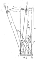
- the bridge platform (1) which can be pivoted about an axis (4) at the end on the ramp side, has an extension (2) which can be folded in and out about the axis (3).
- the dock leveler has a frame (5) on, which is inserted into the recess of the ramp and has in the front part known devices for mounting the drive-over bridge in the rest position.
- this framework is not necessary for the invention.
- an abutment (35) is attached, on which the bearings (14) and (15) are attached, about which the superposed arms (6) and (7) are rotatable .
- the arm (6) carries at its free end a rolling element (9) which runs over the guide (10) attached to the platform and can push the platform upwards.
- the rolling element can be a wheel or a roller and the guide is then a steel plate. If you choose a roller with a circumferential groove as the rolling element, a round steel can be used as a guide, for example.
- the two arms (6) and (7) are connected to each other by the arm (8) via the joints (16) and (18).
- a tension element (11), (12) can engage, the other end of which on the ramp-side frame part or End wall of the ramp recess is fixed in the abutment (19).
- the tension element which preferably consists of a tension part, such as a tension spring, and a connecting part, such as a steel cable, can engage the arm (8) directly or via a lever arm.
- the balance of power can be adapted to the respective requirements. It is also possible, for example, to make the pivot point (14) movable during the lifting process. Because the arms (6) and (7) are moved over the arm (8), an optimal force distribution is obtained and the bridge can be lifted over the entire range of motion with the same effort.
- the favorable force distribution allows the guide (10) to be designed as a flat piece, for example as a steel plate or straight round steel piece.
- the mounting plate (35) can also be changed in its position depending on the desired circumstances and can be moved further forward, for example.
- the drive system according to the invention can also be installed in existing, mechanically operated dock levellers.
- the adjustment of the force required for the movement of the drive-over bridge can then easily be made by increasing the tensile force of the tensioning element (11), (12), for example by shortening the connecting part (12) somewhat.
- This can consist, for example, of a steel cable attached to the bridge, the other end of which can be wound onto a winding device that can be locked against the winding direction. If necessary, the bridge can also be locked in the rest position by suitable measures in the ramp recess.
- this braking device In the unlocked state, this braking device, the construction of which is known to the person skilled in the art, allows the movement of the bridge to be limited upwards. If the bridge is moved downward from the uppermost working position, for example by a load, the locked braking device holds the bridge in the position then reached at the end of the movement process. As already mentioned, in this case the braking device must release the upward movement of the bridge again given a certain magnitude of an upward force acting on the bridge, which is, for example, greater than 200 N. In this case, too, however, it is to be avoided that the force emanating from the drive mechanism lies substantially above the force emanating from the bridge with the extension extended.
- the device according to the invention can be used not only with dock levellers with extendable or fold-out extensions, but also with dock levellers which lie on the vehicle to be loaded without an extension part.
Landscapes
- Engineering & Computer Science (AREA)
- Mechanical Engineering (AREA)
- Bridges Or Land Bridges (AREA)
- Auxiliary Methods And Devices For Loading And Unloading (AREA)
- Load-Engaging Elements For Cranes (AREA)
- Vehicle Body Suspensions (AREA)
- Accommodation For Nursing Or Treatment Tables (AREA)
- Motorcycle And Bicycle Frame (AREA)
- Transmission Devices (AREA)
Priority Applications (5)
| Application Number | Priority Date | Filing Date | Title |
|---|---|---|---|
| AT89103325T ATE80121T1 (de) | 1989-02-24 | 1989-02-24 | Antriebsmechanismus fuer ueberfahrbruecken fuer rampen. |
| ES198989103325T ES2035392T3 (es) | 1989-02-24 | 1989-02-24 | Mecanismo de accionamiento para puentes de paso sobre rampas. |
| EP89103325A EP0383987B1 (de) | 1989-02-24 | 1989-02-24 | Antriebsmechanismus für Überfahrbrücken für Rampen |
| DE8989103325T DE58902208D1 (de) | 1989-02-24 | 1989-02-24 | Antriebsmechanismus fuer ueberfahrbruecken fuer rampen. |
| GR920402194T GR3006395T3 (enExample) | 1989-02-24 | 1992-12-02 |
Applications Claiming Priority (1)
| Application Number | Priority Date | Filing Date | Title |
|---|---|---|---|
| EP89103325A EP0383987B1 (de) | 1989-02-24 | 1989-02-24 | Antriebsmechanismus für Überfahrbrücken für Rampen |
Publications (2)
| Publication Number | Publication Date |
|---|---|
| EP0383987A1 EP0383987A1 (de) | 1990-08-29 |
| EP0383987B1 true EP0383987B1 (de) | 1992-09-02 |
Family
ID=8201013
Family Applications (1)
| Application Number | Title | Priority Date | Filing Date |
|---|---|---|---|
| EP89103325A Expired - Lifetime EP0383987B1 (de) | 1989-02-24 | 1989-02-24 | Antriebsmechanismus für Überfahrbrücken für Rampen |
Country Status (5)
| Country | Link |
|---|---|
| EP (1) | EP0383987B1 (enExample) |
| AT (1) | ATE80121T1 (enExample) |
| DE (1) | DE58902208D1 (enExample) |
| ES (1) | ES2035392T3 (enExample) |
| GR (1) | GR3006395T3 (enExample) |
Family Cites Families (2)
| Publication number | Priority date | Publication date | Assignee | Title |
|---|---|---|---|---|
| DE1048535B (enExample) * | 1959-01-08 | |||
| DE2119056C3 (de) * | 1971-04-20 | 1980-10-23 | Kurt 3015 Wennigsen Alten | Überladebrücke für Rampen u.dgl |
-
1989
- 1989-02-24 ES ES198989103325T patent/ES2035392T3/es not_active Expired - Lifetime
- 1989-02-24 EP EP89103325A patent/EP0383987B1/de not_active Expired - Lifetime
- 1989-02-24 DE DE8989103325T patent/DE58902208D1/de not_active Expired - Fee Related
- 1989-02-24 AT AT89103325T patent/ATE80121T1/de not_active IP Right Cessation
-
1992
- 1992-12-02 GR GR920402194T patent/GR3006395T3/el unknown
Also Published As
| Publication number | Publication date |
|---|---|
| EP0383987A1 (de) | 1990-08-29 |
| ES2035392T3 (es) | 1993-04-16 |
| GR3006395T3 (enExample) | 1993-06-21 |
| ATE80121T1 (de) | 1992-09-15 |
| DE58902208D1 (de) | 1992-10-08 |
Similar Documents
| Publication | Publication Date | Title |
|---|---|---|
| DE69100578T2 (de) | Fahrzeugsitze mit daran befestigtem Gurt. | |
| DE68909281T2 (de) | Verstellbare Säule für ein Lastkraftfahrzeug mit verschiebbarer Abdeckung. | |
| DE2601565C3 (de) | Sicherheits-Sperrvorrichtung für Stützarme eines Fahrzeuges, insbesondere eines fahrbaren Krans | |
| DE19815466A1 (de) | Be- und Entladegerät | |
| DE2458811A1 (de) | Vorrichtung zur handhabung eines fahrzeug-ladekuebels | |
| EP3609833B1 (de) | Hebebühne zum anheben von fahrzeugen | |
| DE2441703A1 (de) | Laderampe | |
| DE1580265C3 (de) | Lastkraftwagen mit einer Plattform zur Mitnahme eines Hubladers | |
| DE20001690U1 (de) | Stützhalterung für einen geparkten Wechselcontainer | |
| EP0383987B1 (de) | Antriebsmechanismus für Überfahrbrücken für Rampen | |
| DE102019206069B3 (de) | Vorrichtung zum Be- und/oder Entladen eines Innenraums eines Fahrzeugs und zum Erleichtern eines Einsteigens in und Aussteigens aus dem Fahrzeug | |
| DE10303508A1 (de) | Separiereinrichtung einer Rollenbahn für Stückgüter | |
| DE1684756C3 (de) | Vorrichtung zum Abstellen von zwei Fahrzeugen übereinander | |
| EP3305589B1 (de) | Ladebordwand mit sturzsicherung | |
| DE20307880U1 (de) | Vorrichtung zum Anheben von Lasten im Kofferraum von Kraftfahrzeugen | |
| DE2631741A1 (de) | Vorrichtung zum ein- und ausladen insbesondere eines in einem rollstuhl sitzenden patienten in ein fahrzeug bzw. aus einem fahrzeug | |
| EP0268047B1 (de) | Schrägaufzug, insbesondere Material- oder Personenaufzug | |
| DE69300244T2 (de) | Hubladeeinrichtung zur Anwendung an einem Lastwagenbehälter. | |
| DE2126460C3 (de) | Laderampe | |
| DE3222697C2 (de) | Mobiler Schienenaufzug mit neigungsverstellbarer Teleskopschiene | |
| DE69101000T2 (de) | Hebbare Ladebordwand mit einem Anschlag zum Halten einer Transportkarre auf ihrer Plattform. | |
| EP0345421B1 (de) | Höhenverstellbarer Podestbock für Theaterbühnen | |
| DE2739981A1 (de) | Aufzugschlitten fuer einen schraegaufzug | |
| EP0386273B1 (de) | Vorrichtung zum Ausschwenken der Verlängerung von Überfahrbrücken für Rampen | |
| DE2126460B2 (de) | Laderampe |
Legal Events
| Date | Code | Title | Description |
|---|---|---|---|
| PUAI | Public reference made under article 153(3) epc to a published international application that has entered the european phase |
Free format text: ORIGINAL CODE: 0009012 |
|
| AK | Designated contracting states |
Kind code of ref document: A1 Designated state(s): AT BE CH DE ES FR GB GR IT LI LU NL SE |
|
| 17P | Request for examination filed |
Effective date: 19900918 |
|
| 17Q | First examination report despatched |
Effective date: 19920210 |
|
| GRAA | (expected) grant |
Free format text: ORIGINAL CODE: 0009210 |
|
| AK | Designated contracting states |
Kind code of ref document: B1 Designated state(s): AT BE CH DE ES FR GB GR IT LI LU NL SE |
|
| REF | Corresponds to: |
Ref document number: 80121 Country of ref document: AT Date of ref document: 19920915 Kind code of ref document: T |
|
| ITF | It: translation for a ep patent filed | ||
| REF | Corresponds to: |
Ref document number: 58902208 Country of ref document: DE Date of ref document: 19921008 |
|
| GBT | Gb: translation of ep patent filed (gb section 77(6)(a)/1977) | ||
| PGFP | Annual fee paid to national office [announced via postgrant information from national office to epo] |
Ref country code: BE Payment date: 19921028 Year of fee payment: 5 |
|
| PGFP | Annual fee paid to national office [announced via postgrant information from national office to epo] |
Ref country code: FR Payment date: 19921127 Year of fee payment: 5 |
|
| PGFP | Annual fee paid to national office [announced via postgrant information from national office to epo] |
Ref country code: GR Payment date: 19921202 Year of fee payment: 5 |
|
| PGFP | Annual fee paid to national office [announced via postgrant information from national office to epo] |
Ref country code: LU Payment date: 19921216 Year of fee payment: 5 |
|
| PGFP | Annual fee paid to national office [announced via postgrant information from national office to epo] |
Ref country code: DE Payment date: 19921218 Year of fee payment: 5 |
|
| ET | Fr: translation filed | ||
| PGFP | Annual fee paid to national office [announced via postgrant information from national office to epo] |
Ref country code: SE Payment date: 19930125 Year of fee payment: 5 |
|
| PGFP | Annual fee paid to national office [announced via postgrant information from national office to epo] |
Ref country code: AT Payment date: 19930126 Year of fee payment: 5 |
|
| PGFP | Annual fee paid to national office [announced via postgrant information from national office to epo] |
Ref country code: CH Payment date: 19930205 Year of fee payment: 5 |
|
| PGFP | Annual fee paid to national office [announced via postgrant information from national office to epo] |
Ref country code: GB Payment date: 19930215 Year of fee payment: 5 Ref country code: ES Payment date: 19930215 Year of fee payment: 5 |
|
| PGFP | Annual fee paid to national office [announced via postgrant information from national office to epo] |
Ref country code: NL Payment date: 19930228 Year of fee payment: 5 |
|
| EPTA | Lu: last paid annual fee | ||
| REG | Reference to a national code |
Ref country code: ES Ref legal event code: FG2A Ref document number: 2035392 Country of ref document: ES Kind code of ref document: T3 |
|
| REG | Reference to a national code |
Ref country code: GR Ref legal event code: FG4A Free format text: 3006395 |
|
| PLBE | No opposition filed within time limit |
Free format text: ORIGINAL CODE: 0009261 |
|
| STAA | Information on the status of an ep patent application or granted ep patent |
Free format text: STATUS: NO OPPOSITION FILED WITHIN TIME LIMIT |
|
| 26N | No opposition filed | ||
| PG25 | Lapsed in a contracting state [announced via postgrant information from national office to epo] |
Ref country code: LU Free format text: LAPSE BECAUSE OF NON-PAYMENT OF DUE FEES Effective date: 19940224 Ref country code: GB Effective date: 19940224 Ref country code: AT Effective date: 19940224 |
|
| PG25 | Lapsed in a contracting state [announced via postgrant information from national office to epo] |
Ref country code: SE Effective date: 19940225 Ref country code: ES Free format text: LAPSE BECAUSE OF NON-PAYMENT OF DUE FEES Effective date: 19940225 |
|
| PG25 | Lapsed in a contracting state [announced via postgrant information from national office to epo] |
Ref country code: LI Effective date: 19940228 Ref country code: CH Effective date: 19940228 Ref country code: BE Effective date: 19940228 |
|
| BERE | Be: lapsed |
Owner name: VAN WIJK NEDERLAND B.V. Effective date: 19940228 |
|
| PG25 | Lapsed in a contracting state [announced via postgrant information from national office to epo] |
Ref country code: GR Free format text: THE PATENT HAS BEEN ANNULLED BY A DECISION OF A NATIONAL AUTHORITY Effective date: 19940831 |
|
| PG25 | Lapsed in a contracting state [announced via postgrant information from national office to epo] |
Ref country code: NL Effective date: 19940901 |
|
| NLV4 | Nl: lapsed or anulled due to non-payment of the annual fee | ||
| GBPC | Gb: european patent ceased through non-payment of renewal fee |
Effective date: 19940224 |
|
| PG25 | Lapsed in a contracting state [announced via postgrant information from national office to epo] |
Ref country code: FR Effective date: 19941031 |
|
| REG | Reference to a national code |
Ref country code: CH Ref legal event code: PL |
|
| PG25 | Lapsed in a contracting state [announced via postgrant information from national office to epo] |
Ref country code: DE Effective date: 19941101 |
|
| REG | Reference to a national code |
Ref country code: FR Ref legal event code: ST Ref country code: GR Ref legal event code: MM2A Free format text: 3006395 |
|
| EUG | Se: european patent has lapsed |
Ref document number: 89103325.0 Effective date: 19940910 |
|
| REG | Reference to a national code |
Ref country code: ES Ref legal event code: FD2A Effective date: 19990405 |
|
| PG25 | Lapsed in a contracting state [announced via postgrant information from national office to epo] |
Ref country code: IT Free format text: LAPSE BECAUSE OF NON-PAYMENT OF DUE FEES;WARNING: LAPSES OF ITALIAN PATENTS WITH EFFECTIVE DATE BEFORE 2007 MAY HAVE OCCURRED AT ANY TIME BEFORE 2007. THE CORRECT EFFECTIVE DATE MAY BE DIFFERENT FROM THE ONE RECORDED. Effective date: 20050224 |