EP0382030B1 - Messvorrichtung zum Erfassen von Wegstrecken - Google Patents
Messvorrichtung zum Erfassen von Wegstrecken Download PDFInfo
- Publication number
- EP0382030B1 EP0382030B1 EP90101669A EP90101669A EP0382030B1 EP 0382030 B1 EP0382030 B1 EP 0382030B1 EP 90101669 A EP90101669 A EP 90101669A EP 90101669 A EP90101669 A EP 90101669A EP 0382030 B1 EP0382030 B1 EP 0382030B1
- Authority
- EP
- European Patent Office
- Prior art keywords
- light
- light guide
- guides
- measuring element
- sensor input
- Prior art date
- Legal status (The legal status is an assumption and is not a legal conclusion. Google has not performed a legal analysis and makes no representation as to the accuracy of the status listed.)
- Expired - Lifetime
Links
- 230000003287 optical effect Effects 0.000 claims description 15
- 238000005259 measurement Methods 0.000 claims description 8
- 238000006073 displacement reaction Methods 0.000 claims description 6
- 239000011248 coating agent Substances 0.000 claims description 3
- 238000000576 coating method Methods 0.000 claims description 3
- 238000011156 evaluation Methods 0.000 claims description 2
- 230000005540 biological transmission Effects 0.000 claims 1
- 239000004020 conductor Substances 0.000 description 8
- 238000005452 bending Methods 0.000 description 4
- 230000008878 coupling Effects 0.000 description 4
- 238000010168 coupling process Methods 0.000 description 4
- 238000005859 coupling reaction Methods 0.000 description 4
- 238000010586 diagram Methods 0.000 description 2
- 238000005516 engineering process Methods 0.000 description 2
- 206010067482 No adverse event Diseases 0.000 description 1
- 238000009530 blood pressure measurement Methods 0.000 description 1
- 230000006735 deficit Effects 0.000 description 1
- 230000001419 dependent effect Effects 0.000 description 1
- 238000011161 development Methods 0.000 description 1
- 230000018109 developmental process Effects 0.000 description 1
- 230000000694 effects Effects 0.000 description 1
- 238000005530 etching Methods 0.000 description 1
- 230000008020 evaporation Effects 0.000 description 1
- 238000001704 evaporation Methods 0.000 description 1
- 239000000835 fiber Substances 0.000 description 1
- 239000000463 material Substances 0.000 description 1
- 230000035945 sensitivity Effects 0.000 description 1
- 230000001953 sensory effect Effects 0.000 description 1
- 238000004544 sputter deposition Methods 0.000 description 1
- 230000002123 temporal effect Effects 0.000 description 1
Images
Classifications
-
- G—PHYSICS
- G01—MEASURING; TESTING
- G01D—MEASURING NOT SPECIALLY ADAPTED FOR A SPECIFIC VARIABLE; ARRANGEMENTS FOR MEASURING TWO OR MORE VARIABLES NOT COVERED IN A SINGLE OTHER SUBCLASS; TARIFF METERING APPARATUS; MEASURING OR TESTING NOT OTHERWISE PROVIDED FOR
- G01D5/00—Mechanical means for transferring the output of a sensing member; Means for converting the output of a sensing member to another variable where the form or nature of the sensing member does not constrain the means for converting; Transducers not specially adapted for a specific variable
- G01D5/26—Mechanical means for transferring the output of a sensing member; Means for converting the output of a sensing member to another variable where the form or nature of the sensing member does not constrain the means for converting; Transducers not specially adapted for a specific variable characterised by optical transfer means, i.e. using infrared, visible, or ultraviolet light
- G01D5/32—Mechanical means for transferring the output of a sensing member; Means for converting the output of a sensing member to another variable where the form or nature of the sensing member does not constrain the means for converting; Transducers not specially adapted for a specific variable characterised by optical transfer means, i.e. using infrared, visible, or ultraviolet light with attenuation or whole or partial obturation of beams of light
- G01D5/34—Mechanical means for transferring the output of a sensing member; Means for converting the output of a sensing member to another variable where the form or nature of the sensing member does not constrain the means for converting; Transducers not specially adapted for a specific variable characterised by optical transfer means, i.e. using infrared, visible, or ultraviolet light with attenuation or whole or partial obturation of beams of light the beams of light being detected by photocells
- G01D5/353—Mechanical means for transferring the output of a sensing member; Means for converting the output of a sensing member to another variable where the form or nature of the sensing member does not constrain the means for converting; Transducers not specially adapted for a specific variable characterised by optical transfer means, i.e. using infrared, visible, or ultraviolet light with attenuation or whole or partial obturation of beams of light the beams of light being detected by photocells influencing the transmission properties of an optical fibre
- G01D5/35383—Mechanical means for transferring the output of a sensing member; Means for converting the output of a sensing member to another variable where the form or nature of the sensing member does not constrain the means for converting; Transducers not specially adapted for a specific variable characterised by optical transfer means, i.e. using infrared, visible, or ultraviolet light with attenuation or whole or partial obturation of beams of light the beams of light being detected by photocells influencing the transmission properties of an optical fibre using multiple sensor devices using multiplexing techniques
-
- G—PHYSICS
- G02—OPTICS
- G02B—OPTICAL ELEMENTS, SYSTEMS OR APPARATUS
- G02B6/00—Light guides; Structural details of arrangements comprising light guides and other optical elements, e.g. couplings
- G02B6/24—Coupling light guides
- G02B6/26—Optical coupling means
- G02B6/28—Optical coupling means having data bus means, i.e. plural waveguides interconnected and providing an inherently bidirectional system by mixing and splitting signals
- G02B6/2804—Optical coupling means having data bus means, i.e. plural waveguides interconnected and providing an inherently bidirectional system by mixing and splitting signals forming multipart couplers without wavelength selective elements, e.g. "T" couplers, star couplers
- G02B6/2821—Optical coupling means having data bus means, i.e. plural waveguides interconnected and providing an inherently bidirectional system by mixing and splitting signals forming multipart couplers without wavelength selective elements, e.g. "T" couplers, star couplers using lateral coupling between contiguous fibres to split or combine optical signals
- G02B6/2835—Optical coupling means having data bus means, i.e. plural waveguides interconnected and providing an inherently bidirectional system by mixing and splitting signals forming multipart couplers without wavelength selective elements, e.g. "T" couplers, star couplers using lateral coupling between contiguous fibres to split or combine optical signals formed or shaped by thermal treatment, e.g. couplers
- G02B2006/2839—Optical coupling means having data bus means, i.e. plural waveguides interconnected and providing an inherently bidirectional system by mixing and splitting signals forming multipart couplers without wavelength selective elements, e.g. "T" couplers, star couplers using lateral coupling between contiguous fibres to split or combine optical signals formed or shaped by thermal treatment, e.g. couplers fabricated from double or twin core fibres
-
- G—PHYSICS
- G02—OPTICS
- G02B—OPTICAL ELEMENTS, SYSTEMS OR APPARATUS
- G02B6/00—Light guides; Structural details of arrangements comprising light guides and other optical elements, e.g. couplings
- G02B6/02—Optical fibres with cladding with or without a coating
- G02B6/02042—Multicore optical fibres
-
- G—PHYSICS
- G02—OPTICS
- G02B—OPTICAL ELEMENTS, SYSTEMS OR APPARATUS
- G02B6/00—Light guides; Structural details of arrangements comprising light guides and other optical elements, e.g. couplings
- G02B6/02—Optical fibres with cladding with or without a coating
- G02B6/036—Optical fibres with cladding with or without a coating core or cladding comprising multiple layers
- G02B6/03616—Optical fibres characterised both by the number of different refractive index layers around the central core segment, i.e. around the innermost high index core layer, and their relative refractive index difference
- G02B6/03688—Optical fibres characterised both by the number of different refractive index layers around the central core segment, i.e. around the innermost high index core layer, and their relative refractive index difference having 5 or more layers
Definitions
- the invention relates to a device for distance measurement with an optical measuring element which has at least two closely spaced light guides, which consists of an elongated support in which the light guides are embedded parallel to each other, at one end, the sensor input, against lateral Shifts is held and in another area with joint bending of the carrier and the light guide is laterally displaceable by the distance to be shifted, which is designed such that a certain amount of light coupled into a light guide couples into the other light guide when the light guide is bent , and which has a mirror coating, by means of which light which propagates in the light guides towards the other end of the measuring element is reflected back to the sensor input, with means for coupling light into the sensor input of the measuring element, and with a device by which d The coupled light reflected by the mirroring and emerging at the sensor input is detected and the displacement or distance is determined from the intensity and propagation time of this light.
- an optical measuring element which has at least two closely spaced light guides, which consists of an elongated support in which the light guides
- DE-C-35 41 733 shows a measuring device in which two optical resonators used for pressure measurement form the measuring element coupled to a laser light source and an evaluation circuit.
- the optical resonators are formed here by gradient index optical waveguide sections which are arranged on the top and the bottom of a sensor body which can be elastically deformed by pressure. When pressure is applied, the resonators are detuned in opposite directions and the detuning is the measure of the pressure applied.
- such a measuring device is not suitable for distance measurement, since the deflections which can be achieved do not result in a sufficient measuring section.
- the invention has for its object to provide a device for distance measurement with a measuring element working on an optical basis and a sufficient distance, which ensures measurement using the deflection and bending of light guides.
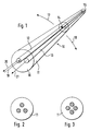
- the principle of a measuring element 10 consists of waveguides 12, 13 arranged in a carrier 11 (sheath), of which the waveguide 12 is shorter than the waveguide 13.
- the ends 14, 15 of these waveguides 12, 13 opposite the sensor input 16 are mirrored.
- FIGS. 2 and 3 show, it is also possible to embed three or four waveguides of different lengths in a carrier 11.
- the measuring element 10 is held at the sensor input 16 and at the opposite end against lateral displacements but can be deflected in its central region as indicated by the arrows 17, 18.
- the shorter waveguide 12, as indicated by arrow 19 is supplied with light, for example light emitted in the form of a pulse, then in the absence of deflection this light is reflected by the mirrored end 14 and can be detected and evaluated by an optical time division multiplex device, not shown. If there is no deflection, all of the light indicated by the arrow 20 is reflected and the time-division multiplex device does not display any deflections. If, however, a deflection has occurred, a certain amount of the light is coupled into the waveguide 13 by the coupled light 19, and is guided to the sensor input and to the mirrored end 15. Light pulses coupled into the waveguide 12 are therefore coupled from the sensor input depending on the bend into other waveguides and reflected due to the different waveguide lengths. The time-division multiplex device receives the reflections and evaluates them according to relative intensity and transit time to determine the deflected path.
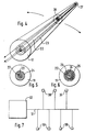
- a measuring element 10 with a core conductor 22 and coaxial ring conductors 23, 24, 25.
- the core conductor 22 is shorter than the coaxial ring conductor and the ends 26, 27 are also mirrored.
- the function results in comparison with the exemplary embodiments according to FIG. 1-3 no difference.
- the measured intensities are also dependent on the bending state and are reciprocal to one another, i.e. a decrease in intensity in one channel results in an increase in the other channel.
- a steady decrease in the reflected back intensities e.g. due to temperature fluctuations has no influence on the measurement result if the intensity ratio is formed.
- a measuring element with a core conductor and ring conductors also has the advantage of easier coupling to a normal light guide or fiber, but such conductor forms must be specially developed with regard to their coupling sensitivity.
- Evaporation or sputtering technologies can be used to mirror the ends of the light guides, but etching technologies can be used in the same way.
- the sensory measuring element can be designed in such a way that an absolute measurement is also possible, so that short-term system failures do not cause any impairments.
- the block diagram according to FIG. 7 shows, it is possible to equip a large number of sensors 30 with the measuring element 10 and to couple them to an optical time-division multiplex device 32 via an optical data bus 31.
- the local position of the sensors is then characterized by a temporal position of the measured refelexes, the advantage of a closed optical light path being obtained via the data bus results.
- the effects of moisture, icing or soiling therefore have no adverse effects on the measurement.
Landscapes
- Physics & Mathematics (AREA)
- General Physics & Mathematics (AREA)
- Length Measuring Devices By Optical Means (AREA)
Description
- Die Erfindung bezieht sich auf eine Vorrichtung zur Wegstreckenmessung mit einem optischen Meßelement das mindestens zwei in dichtem Abstand nebeneinander angeordnete Lichtleiter aufweist, das aus einem länglichen Träger besteht, in den die Lichtleiter zueinander parallel eingebettet sind, das an einem Ende, dem Sensoreingang, gegen seitliche Verschiebungen gehalten ist und in einem anderen Bereich unter gemeinsamer Verbiegung des Trägers und der Lichtleiter um die zu verschiebende Wegstrecke seitlich verschiebbar ist, das derart ausgebildet ist, daß bei bestimmter Verbiegung der Lichtleiter ein bestimmter Betrag des in einen Lichtleiter eingekoppelten Lichts in den anderen Lichtleiter überkoppelt, und das eine Verspiegelung aufweist, durch das Licht, das sich in den Lichtleitern zum anderen Ende des Meßelements hin ausbreitet, zum Sensoreingang zurückreflektiert wird, mit Mitteln zum Einkoppeln von Licht am Sensoreingang des Meßelements, und mit einer Einrichtung, durch die das überkoppelte, von der Verspiegelung reflektierte und am Sensoreingang austretende Licht erfaßt wird und aus der Intensität und Laufzeit dieses Lichtes die Verschiebung bzw. Wegstrecke bestimmt wird. Eine derartige Vorrichtung wird in DE-A-3 016 104 beschrieben.
- Meßvorrichtungen mit auf optischer Basis arbeitenden Meßelementen sind grundsätzlich bekannt. So zeigt die DE-C-35 41 733 eine Meßvorrichtung, in der zwei zur Druckmessung eingesetzte optische Resonatoren das mit einer Laserlichtquelle und einer Auswerteschaltung gekoppelte Meßelement bilden. Die optischen Resonatoren werden hierbei durch Gradientenindex-Lichtwellenleiterabschnitte gebildet, die auf der Oberseite und der Unterseite eines durch Druck elastisch verformbaren Sensorkörpers angeordnet sind. Mit dem Aufbringen von Druck wird eine gegenläufige Verstimmung der Resonatoren bewirkt und die Verstimmung ist das Maß für den aufgebrachten Druck. Zur Wegmessung ist eine solche Meßvorrichtung aber nicht geeignet, da die erzielbaren Auslenkungen keine hinreichende Meßstrecke ergeben.
- Weiterhin ist es aus der US-A-4 717 253 bekannt, das von einem Eingangslichtleiter in einen längeren Ausgangslichtleiter überkoppelnde Licht zweier nebeneinanderliegender Lichtleiter zu erfassen. Ein solches Meßelement ist nur in der Lage relativ kleine Abstände zu messen. Bei dieser Ausbildung sind die Lichtleiter in einem Material eingebettet und es wird sich wegen ändernder mechanischer Spannung entlang der Meßstelle - insbesondere an den Enden der Meßstelle, wo die Spannung gegen Null gehen muß - die Verschiebung der Lichtleiter entlang der Meßstelle ändern, was zur Verbiegung der Lichtleiter führen wird und damit auch zu Änderungen der Überkopplung beitragen wird.
- Der Erfindung liegt die Aufgabe zugrunde eine Vorrichtung zur Wegstreckenmessung mit auf optischer Basis arbeitendem Meßelement und ausreichender Wegstrecke zu schaffen, die unter Ausnutzung von Auslenkung und Verbiegung von Lichtleitern eine Messung gewährleistet.
- Diese Aufgabe wird erfindungsgemäß entsprechend dem kennzeichnenden Teil des Anspruchs 1 gelöst.
- Weiterbildungen und vorteilhafte Ausgestaltungen der Erfindung sind den Ansprüchen 2 bis 5 zu entnehmen.
- Die Erfindung wird anhand der beiliegenden Zeichnung näher erläutert. Es zeigen:
- Fig. 1 ein zwei Wellenleiter aufweisendes Meßelement,
- Fig. 2 ein Querschnitt eines Meßelementes,
- Fig. 3 einen weiteren Querschnitt eines Meßelementes,
- Fig. 4 ein Meßelement mit Kern- und Ringleitern,
- Fig. 5 einen Querschnitt eines Meßelementes,
- Fig. 6 einen weiteren Querschnitt eines Meßelementes und
- Fig. 7 ein Blockschaltbild.
- Wie die Darstellung nach Fig. 1 zeigt, besteht das Prinzip eines Meßelementes 10 aus in einem Träger 11 (Hülle) angeordneten Wellenleitern 12, 13, wovon der Wellenleiter 12 kürzer als der Wellenleiter 13 ist. Die dem Sensoreneingang 16 gegenüberliegenden Enden 14, 15 dieser Wellenleiter 12, 13 sind verspiegelt. Wie Fig. 2 und Fig. 3 zeigen ist es auch möglich drei oder vier Wellenleiter unterschiedlicher Länge in einen Träger 11 einzubetten. Das Meßelement 10 ist am Sensoreingang 16 und am gegenüberliegenden Ende gegen seitliche Verschiebungen gehalten aber in seinem Mittelbereich wie durch die Pfeile 17, 18 angedeutet auslenkbar. Wenn der kürzere Wellenleiter 12, wie durch Pfeil 19 angedeutet mit Licht, z.B. impulsförmig abgestrahltem Licht versorgt wird, dann wird bei fehlender Auslenkung dieses Licht vom verspiegelten Ende 14 reflektiert und kann von einem nicht dargestellten optischen Zeitmultiplexgerät erfaßt und ausgewertet werden. Bei fehlender Auslenkung wird also das gesamte durch den Pfeil 20 angedeutete Licht reflektiert und das Zeitmultiplexgerät zeigt keine Auslenkungen an. Ist aber eine Auslenkung erfolgt, dann wird vom eingekoppelten Licht 19 ein bestimmter Betrag des Lichtes in den Wellenleiter 13 übergekoppelt, und zum Sensoreingang und zum verspiegelten Ende 15 geleitet. In den Wellenleiter 12 eingekoppelte Lichtimpulse werden daher vom Sensoreneingang kommend je nach Biegung in andere Wellenleiter übergekoppelt und aufgrund der verschiedenen Wellenleiterlängen reflektiert. Das Zeitmultiplexgerät empfängt die Reflexe und wertet diese nach relativer Intensität und Laufzeit zur Ermittlung der ausgelenkten Wegstrecke aus.
- Wie in Fig. 4 bis Fig. 6 dargestellt, ist es auch möglich ein Meßelement 10 mit einem Kernleiter 22 und koaxialen Ringleitern 23, 24, 25 aufzubauen. Der Kernleiter 22 ist dabei kürzer als die koaxialen Ringleiter und die Enden 26, 27 sind ebenfalls verspiegelt. In der Funktion ergibt sich gegenüber den Ausführungsbeispielen nach Fi. 1-3 kein Unterschied. Die gemessenen Intensitäten sind ebenfalls vom Biegezustand abhängig und zueinander reziprok, d.h. eine Intensitätsabnahme in einem Kanal hat eine Zunahme im anderen Kanal zur Folge. Eine gleichmäßige Abnahme der zurückreflektierten Intensitäten z.B. infolge von Temperaturschwankungen, ist ohne Einfluß auf das Meßergebnis, wenn das Intensitätsverhältnis gebildet wird. Ein Meßelement mit einem Kernleiter und Ringleitern hat darüber hinaus den Vorteil einer leichteren Ankopplung an einen normalen Lichtleiter bzw. Faser, aber solche Leiterformen müssen speziell hinsichtlich ihrer Koppelempfindlichkeit entwickelt werden. Für das Verspiegeln der Lichtleiterenden können Aufdampftechnologien oder Sputtertechnologien verwendet werden, aber Ätztechnologien sind in gleicher Weise dafür verwendbar. Das empfindungsgemäße Meßelement kann so ausgelegt werden, daß auch eine Absolutmessung möglich ist, wodurch kurzzeitige Systemausfälle keine Beeinträchtigungen hervorrufen.
- Wie das Blockschaltbild nach Fig. 7 zeigt, ist es möglich eine Vielzahl von Sensoren 30 mit dem Meßelement 10 auszurüsten und über einen optischen Datenbus 31 an ein optisches Zeitmultiplexgerät 32 anzukoppeln. Die örtliche Lage der Sensoren wird dann durch eine zeitliche Lage der gemessenen Refelexe gekennzeichnet, wobei sich über den Datenbus der Vorteil eines geschlossenen optischen Lichtweges ergibt. Feuchtigkeitseinwirkungen, Vereisungen oder Verschmutzungen bleiben daher ohne nachteilige Wirkungen auf die Messung.
-
- 10
- Meßelement
- 11
- Träger (Hülle)
- 12
- Wellenleiter
- 13
- Wellenleiter
- 14
- verspiegeltes Ende vom Wellenleiter 12
- 15
- Verspiegeltes Ende vom Wellenleiter 13
- 16
- Sensoreingang
- 17
- Pfeil
- 18
- Pfeil
- 19
- Pfeil
- 20
- Pfeil
- 21
- Pfeil
- 22
- Kernleiter
- 23
- Ringleiter
- 24
- Ringleiter
- 25
- Ringleiter
- 26
- verspiegeltes Ende vom Wellenleiter 22
- 27
- verspiegeltes Ende vom Rindleiter 23
- 30
- Sensor
- 31
- optischer Datenbus
- 32
- Zeitmultiplexgerät
Claims (5)
- Vorrichtung zur Wegstreckenmessung
mit einem optischen Meßelement (10),
das mindestens zwei in dichtem Abstand nebeneinander angeordnete Lichtleiter (12,13,22-25) aufweist,
das aus einem länglichen Träger (11) besteht, in den die Lichtleiter (12,13,22-25) zueinander parallel eingebettet sind
und von dessen einem Ende, dem Sensoreingang (16), die Lichtleiter ausgehen, das am Sensoreingang (16) gegen seitliche Verschiebungen gehalten ist und in einem anderen Bereich unter gemeinsamer Verbiegung des Trägers (11) und der Lichtleiter (12,13,22-25) um die zu verschiebende Wegstrecke seitlich verschiebbar ist,
das derart ausgebildet ist, daß bei bestimmter Verbiegung der Lichtleiter ein bestimmter Betrag des in einen Lichtleiter (12,22) eingekoppelten Lichts (19) in den anderen Lichtleiter (13,23-25) überkoppelt, und
das eine Verspiegelung aufweist, durch das Licht, das sich in den Lichtleitern (12,13,22-25) zum anderen Ende des Meßelements (10) hin ausbreitet, zum Sensoreingang (16) zurückreflektiert wird,
mit Mitteln zum Einkoppeln von Licht am Sensoreingang des Meßelements (10), und
mit einer Einrichtung (30,32), durch die das überkoppelte, von der Verspiegelung reflektierte und am Sensoreingang (16) austretende Licht erfaßt wird und aus der Intensität und Laufzeit dieses Lichtes die Verschiebung bzw. Wegstrecke bestimmt wird,
dadurch gekennzeichnet, daß
die Mittel zum Einkoppeln von Licht in das Meßelement (10) Licht in nur einen Lichtleiter, den Eingangsleiter (12,22), einkoppeln,
daß der mindestens eine andere Lichtleiter, der Ausgangslichtleiter (13,23-25), an seinem dem Sensoreingang (16) gegenüberliegenden Ende länger ist als der Eingangslichtleiter (12,22), daß jeder Lichtleiter (12, 13, 22-25) an seinem, dem Sensoreingang (16) gegenüberliegenden Ende (14, 15, 26, 27) verspiegelt ist, daß das Meßelement (10) derart ausgebildet ist, daß bei fehlender Verbiegung der Leiter kein Licht vom Eingangs- zum Ausgangslichtleiter überkoppelt und
daß die genannte Einrichtung (30,32) bei Reflexion des gesamten eingekoppelten Lichts vom verspiegelten Ende (14) des Eingangslichtleiters (12,22) keine Verschiebung anzeigt. - Meßvorrichtung nach Anspruch 1, dadurch gekennzeichnet, daß das Meßelement (10) weitere im Träger (11) angeordnete parallele und an ihren Enden verspiegelte Lichtleiter unterschiedlicher Länge aufweist.
- Meßvorrichtung nach Anspruch 1, dadurch gekennzeichnet, daß die Lichtleiter aus einem kürzeren Kernleiter (22) und koaxial dazu verlaufenden längeren Ringleitern bestehen.
- Meßvorrichtung nach einem der Ansprüche 1 oder 2, dadurch gekennzeichnet, daß für die elektronische Schaltung ein optisches Zeitmultiplexgerät (32) vorgesehen ist.
- Meßvorrichtung nach einem der Ansprüche 1 bis 3, dadurch gekennzeichnet, daß das optische Zeitmultiplexgerät (32) über einen optischen Datenbus (31) mehrere Sensoren (30) ansteuert bzw. deren Reaktion zur Auswertung empfängt.
Applications Claiming Priority (2)
| Application Number | Priority Date | Filing Date | Title |
|---|---|---|---|
| DE3903881 | 1989-02-10 | ||
| DE3903881A DE3903881C1 (de) | 1989-02-10 | 1989-02-10 |
Publications (2)
| Publication Number | Publication Date |
|---|---|
| EP0382030A1 EP0382030A1 (de) | 1990-08-16 |
| EP0382030B1 true EP0382030B1 (de) | 1995-11-02 |
Family
ID=6373737
Family Applications (1)
| Application Number | Title | Priority Date | Filing Date |
|---|---|---|---|
| EP90101669A Expired - Lifetime EP0382030B1 (de) | 1989-02-10 | 1990-01-27 | Messvorrichtung zum Erfassen von Wegstrecken |
Country Status (4)
| Country | Link |
|---|---|
| US (1) | US5023446A (de) |
| EP (1) | EP0382030B1 (de) |
| JP (1) | JPH02259502A (de) |
| DE (1) | DE3903881C1 (de) |
Families Citing this family (3)
| Publication number | Priority date | Publication date | Assignee | Title |
|---|---|---|---|---|
| DE4422152C2 (de) * | 1994-06-27 | 2000-02-03 | Daimler Chrysler Aerospace | Verfahren und Anordnung zum Optimieren der aerodynamischen Wirkung eines Tragflügels |
| JP3728511B2 (ja) * | 2003-07-07 | 2005-12-21 | 国立大学法人名古屋大学 | 移動式3次元構造測定装置 |
| CN107101610B (zh) * | 2017-05-25 | 2023-07-28 | 公安部四川消防研究所 | 可用于建筑结构形变监测的位移监测系统 |
Citations (1)
| Publication number | Priority date | Publication date | Assignee | Title |
|---|---|---|---|---|
| DE3016104A1 (de) * | 1980-04-25 | 1981-10-29 | Siemens AG, 1000 Berlin und 8000 München | Sensorvorrichtung mit einer als empfindliches element dienenden lichtleitfaser |
Family Cites Families (5)
| Publication number | Priority date | Publication date | Assignee | Title |
|---|---|---|---|---|
| DE2457930A1 (de) * | 1974-12-07 | 1976-06-10 | Licentia Gmbh | Verfahren zur fehlerortung bei glasfaserlichtleitern |
| US4482890A (en) * | 1981-01-22 | 1984-11-13 | The Secretary Of State For Defence In Her Britannic Majesty's Government Of The United Kingdom Of Great Britain And Northern Ireland | Weight responsive intrusion detector using dual optical fibers |
| AU4064085A (en) * | 1984-03-08 | 1985-09-24 | Optical Technologies, Inc. | Fluid flow sensing apparatus for in vivo and industrial applications employing novel differential optical fiber pressure sensors |
| US4717253A (en) * | 1985-11-22 | 1988-01-05 | Massachusetts Institute Of Technology | Optical strain gauge |
| DE3541733C1 (de) * | 1985-11-26 | 1986-11-20 | Fraunhofer-Gesellschaft zur Förderung der angewandten Forschung e.V., 8000 München | Faseroptische Fabry-Perot-Einrichtung |
-
1989
- 1989-02-10 DE DE3903881A patent/DE3903881C1/de not_active Expired - Fee Related
-
1990
- 1990-01-24 JP JP2012761A patent/JPH02259502A/ja active Pending
- 1990-01-27 EP EP90101669A patent/EP0382030B1/de not_active Expired - Lifetime
- 1990-02-12 US US07/479,381 patent/US5023446A/en not_active Expired - Fee Related
Patent Citations (1)
| Publication number | Priority date | Publication date | Assignee | Title |
|---|---|---|---|---|
| DE3016104A1 (de) * | 1980-04-25 | 1981-10-29 | Siemens AG, 1000 Berlin und 8000 München | Sensorvorrichtung mit einer als empfindliches element dienenden lichtleitfaser |
Non-Patent Citations (2)
| Title |
|---|
| CONFERENCE PROCEEDINGS IEEE SOUTHEASTCON 1986, 23.-25. März 1986, Seiten 91-94, Richmond, Virginia, USA ; J.C. SHIH et al.: "Concentric core optical fiber strain sensor" * |
| HALBLEITER-SCHALTUNGSTECHNIK, 5. Auflage, Springer 1980, Berlin, DE, Seiten 466-468, U. TIEFZE et al. * |
Also Published As
| Publication number | Publication date |
|---|---|
| DE3903881C1 (de) | 1990-04-12 |
| JPH02259502A (ja) | 1990-10-22 |
| US5023446A (en) | 1991-06-11 |
| EP0382030A1 (de) | 1990-08-16 |
Similar Documents
| Publication | Publication Date | Title |
|---|---|---|
| DE69912301T2 (de) | Sensor zur messung mechanischer spannungen mit fiber-optischen bragg gittern | |
| DE3715693C1 (de) | Flaechiger,taktiler Sensor | |
| CH455304A (de) | Vorrichtung zum Messen kleiner Abstände | |
| DE3409207A1 (de) | Optischer sensor | |
| EP0078939A1 (de) | Stabähnliche Vorrichtung zum Erfassen des jeweiligen Niveaus von Flüssigkeiten in Behältern, Kanälen o. dgl. | |
| EP0006530A1 (de) | Faseroptisches Temperaturmessgerät | |
| DE3510704A1 (de) | Optisches messgeraet | |
| DE3832569A1 (de) | Faseroptischer sensor | |
| DE3733549C2 (de) | ||
| EP0445362B1 (de) | Vorrichtung zum Messen einer magnetischen Induktion | |
| CH697873B1 (de) | Formteil als optischer Lichtleiter. | |
| EP0448982B1 (de) | Positionsmesseinrichtung | |
| EP0382030B1 (de) | Messvorrichtung zum Erfassen von Wegstrecken | |
| DE3590229T1 (de) | Optischer Sensor | |
| EP0237850A1 (de) | Faseroptischer Sensor für Flüssigkeitsstandanzeiger oder -niveauregler | |
| DE3710041C2 (de) | ||
| DE3415242C1 (de) | Faseroptischer Sensor | |
| DE3630401C1 (de) | Optischer Entfernungsmesser | |
| DE3717687C1 (de) | Faseroptischer Stellwertgeber | |
| EP3857165A1 (de) | Faseroptischer sensor, datenhandschuh und verfahren zur erfassung einer krümmung | |
| EP0412309B1 (de) | Faserkreisel vom Sagnac-Typ | |
| DE3630026C2 (de) | Einrichtung zur Feststellung von Teilentladungen in Hochspannungsanlagen | |
| DE19962078B4 (de) | Verfahren und Vorrichtung zur interferentiellen Abstandsmessung | |
| DE19502007C2 (de) | Verfahren zum Herstellen eines Sensorkopfes für eine Temperaturmeßvorrichtung | |
| DE10115826A1 (de) | Verfahren zur Messung der Position oder der Form eines Objekts bzw. einer Objektkontur in einem Überwachungsbereich mit einem optoelektronischen Messgerät, sowie optoelektronisches Messgerät |
Legal Events
| Date | Code | Title | Description |
|---|---|---|---|
| PUAI | Public reference made under article 153(3) epc to a published international application that has entered the european phase |
Free format text: ORIGINAL CODE: 0009012 |
|
| AK | Designated contracting states |
Kind code of ref document: A1 Designated state(s): CH FR GB IT LI NL SE |
|
| 17P | Request for examination filed |
Effective date: 19900908 |
|
| RAP1 | Party data changed (applicant data changed or rights of an application transferred) |
Owner name: DEUTSCHE AIRBUS GMBH |
|
| 17Q | First examination report despatched |
Effective date: 19910702 |
|
| RAP1 | Party data changed (applicant data changed or rights of an application transferred) |
Owner name: DEUTSCHE AEROSPACE AIRBUS GMBH |
|
| RAP1 | Party data changed (applicant data changed or rights of an application transferred) |
Owner name: DAIMLER-BENZ AEROSPACE AIRBUS GESELLSCHAFT MIT BES |
|
| GRAA | (expected) grant |
Free format text: ORIGINAL CODE: 0009210 |
|
| AK | Designated contracting states |
Kind code of ref document: B1 Designated state(s): CH FR GB IT LI NL SE |
|
| ITF | It: translation for a ep patent filed |
Owner name: INVENTION S.N.C. |
|
| REG | Reference to a national code |
Ref country code: CH Ref legal event code: NV Representative=s name: PATENTANWAELTE GEORG ROEMPLER UND ALDO ROEMPLER |
|
| GBT | Gb: translation of ep patent filed (gb section 77(6)(a)/1977) |
Effective date: 19960109 |
|
| NLT2 | Nl: modifications (of names), taken from the european patent patent bulletin |
Owner name: DAIMLER-BENZ AEROSPACE AIRBUS GESELLSCHAFT MIT BES |
|
| ET | Fr: translation filed | ||
| PGFP | Annual fee paid to national office [announced via postgrant information from national office to epo] |
Ref country code: NL Payment date: 19960626 Year of fee payment: 7 |
|
| PLBE | No opposition filed within time limit |
Free format text: ORIGINAL CODE: 0009261 |
|
| STAA | Information on the status of an ep patent application or granted ep patent |
Free format text: STATUS: NO OPPOSITION FILED WITHIN TIME LIMIT |
|
| 26N | No opposition filed | ||
| PGFP | Annual fee paid to national office [announced via postgrant information from national office to epo] |
Ref country code: SE Payment date: 19970130 Year of fee payment: 8 |
|
| PG25 | Lapsed in a contracting state [announced via postgrant information from national office to epo] |
Ref country code: NL Effective date: 19970801 |
|
| NLV4 | Nl: lapsed or anulled due to non-payment of the annual fee |
Effective date: 19970801 |
|
| PG25 | Lapsed in a contracting state [announced via postgrant information from national office to epo] |
Ref country code: SE Free format text: LAPSE BECAUSE OF NON-PAYMENT OF DUE FEES Effective date: 19980128 |
|
| EUG | Se: european patent has lapsed |
Ref document number: 90101669.1 |
|
| REG | Reference to a national code |
Ref country code: CH Ref legal event code: PFA Free format text: DAIMLER-BENZ AEROSPACE AIRBUS GESELLSCHAFT MIT BESCHRAENKTER HAFTUNG TRANSFER- DAIMLERCHRYSLER AEROSPACE AIRBUS GESELLSCHAFT MIT BESCHRAENKTER HAFTUNG |
|
| REG | Reference to a national code |
Ref country code: FR Ref legal event code: CD |
|
| REG | Reference to a national code |
Ref country code: GB Ref legal event code: IF02 |
|
| PGFP | Annual fee paid to national office [announced via postgrant information from national office to epo] |
Ref country code: GB Payment date: 20020117 Year of fee payment: 13 |
|
| PGFP | Annual fee paid to national office [announced via postgrant information from national office to epo] |
Ref country code: FR Payment date: 20020122 Year of fee payment: 13 |
|
| PGFP | Annual fee paid to national office [announced via postgrant information from national office to epo] |
Ref country code: CH Payment date: 20020430 Year of fee payment: 13 |
|
| PG25 | Lapsed in a contracting state [announced via postgrant information from national office to epo] |
Ref country code: GB Free format text: LAPSE BECAUSE OF NON-PAYMENT OF DUE FEES Effective date: 20030127 |
|
| PG25 | Lapsed in a contracting state [announced via postgrant information from national office to epo] |
Ref country code: LI Free format text: LAPSE BECAUSE OF NON-PAYMENT OF DUE FEES Effective date: 20030131 Ref country code: CH Free format text: LAPSE BECAUSE OF NON-PAYMENT OF DUE FEES Effective date: 20030131 |
|
| REG | Reference to a national code |
Ref country code: CH Ref legal event code: PL |
|
| GBPC | Gb: european patent ceased through non-payment of renewal fee | ||
| PG25 | Lapsed in a contracting state [announced via postgrant information from national office to epo] |
Ref country code: FR Free format text: LAPSE BECAUSE OF NON-PAYMENT OF DUE FEES Effective date: 20030930 |
|
| REG | Reference to a national code |
Ref country code: FR Ref legal event code: ST |
|
| PG25 | Lapsed in a contracting state [announced via postgrant information from national office to epo] |
Ref country code: IT Free format text: LAPSE BECAUSE OF NON-PAYMENT OF DUE FEES;WARNING: LAPSES OF ITALIAN PATENTS WITH EFFECTIVE DATE BEFORE 2007 MAY HAVE OCCURRED AT ANY TIME BEFORE 2007. THE CORRECT EFFECTIVE DATE MAY BE DIFFERENT FROM THE ONE RECORDED. Effective date: 20050127 |
|
| APAH | Appeal reference modified |
Free format text: ORIGINAL CODE: EPIDOSCREFNO |