EP0381052B1 - Dispositif et méthode pour arroser des surfaces - Google Patents
Dispositif et méthode pour arroser des surfaces Download PDFInfo
- Publication number
- EP0381052B1 EP0381052B1 EP19900101482 EP90101482A EP0381052B1 EP 0381052 B1 EP0381052 B1 EP 0381052B1 EP 19900101482 EP19900101482 EP 19900101482 EP 90101482 A EP90101482 A EP 90101482A EP 0381052 B1 EP0381052 B1 EP 0381052B1
- Authority
- EP
- European Patent Office
- Prior art keywords
- spray nozzle
- spray
- liquid
- sprayed
- working direction
- Prior art date
- Legal status (The legal status is an assumption and is not a legal conclusion. Google has not performed a legal analysis and makes no representation as to the accuracy of the status listed.)
- Expired - Lifetime
Links
Images


Classifications
-
- B—PERFORMING OPERATIONS; TRANSPORTING
- B08—CLEANING
- B08B—CLEANING IN GENERAL; PREVENTION OF FOULING IN GENERAL
- B08B3/00—Cleaning by methods involving the use or presence of liquid or steam
- B08B3/02—Cleaning by the force of jets or sprays
- B08B3/024—Cleaning by means of spray elements moving over the surface to be cleaned
Definitions
- the invention first relates to a device according to the preamble of claim 1, as has become known for example from DE-PS 32 29 720.
- the invention is based on the object of expanding the field of use of such known devices, and this is achieved by the characterizing features of claim 1.
- the series connection of two nozzles is known per se, it is a special feature in combination with the separate liquid supply because so that each of the nozzles can be assigned a different function, which functions are to be carried out in succession.
- the first spray nozzle - in the working direction - provides pre-cleaning, for example with a lower pressure, whereupon the downstream second nozzle takes over, in a single operation, the post-cleaning, which is carried out, for example, with a higher pressure.
- devices of the generic type are operated under high pressure of at least 1000 bar and the like for cleaning ship hulls, buildings or concrete walls and the like. used.
- high pressure and the energy applied by the high-pressure pump lead to massive heating of the sprayed surface, which causes the residual water to evaporate rapidly or almost immediately or the treated surface to dry.
- this phenomenon can now be used to carry out a work step which is usually carried out separately together with the first if the training according to claim 2 is met. It is then possible to apply a new color primer immediately after cleaning.
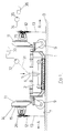
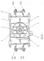
- a spray housing 2 is fastened to a support frame 1, in which two spray nozzles 4 (FIG. 3) seated on arms 3 are rotatably mounted about an axis of rotation 5.
- the liquid feed line 6 also lies on this axis of rotation 5, i.e. that the rotary body formed by the arms 3 and the spray nozzles 4 is expediently mounted about a hollow axis forming the feed.
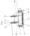
- this is sealed on its lower, open side facing the surface 7 to be sprayed by a concentric sealing apron, which is expediently formed by a row of bristles 8 (see FIG. 2).
- Rollers 9 are attached to the support frame 1 to determine the working direction. In this way, the carriage 1, 9 thus formed can be moved according to FIG. 1 either in a working direction A or in a working direction B. All parts described so far are state of the art.
- fastening devices 11 are attached to the support frame 1 at the front and rear.
- Figures 2 and 3 show that there are actually a pair of fastening devices 11a, 11b.
- spray nozzles 12 designed in the manner of spray guns can be fastened to the support frame 1, the spray jet of which runs along the spray axes 13 in the manner shown in FIGS. 1 and 2.
- the fastening devices 11a, 11b expediently hold the associated spray nozzles 12 on a line running transversely to the working direction.
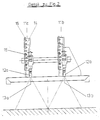
- at least one of the fastening devices is preferably provided with an adjusting device.
- the adjustment device has a plate 14 for rough height adjustment (and thus for the rough adjustment of the sprayed surface area), which is provided at intervals with fastening recesses 15, via which the plate 14 can be fixed to a stand 16.
- a fine adjustment can also be provided.
- the angle of inclination of the spray axis 13 to the surface 7 to be sprayed can be set by known measures which are not explained in detail.
- the distance of the jet of the nozzles 12 from the spray housing 2 can thus also be set if there are differences in the drying time.
- the supply of the liquid or paint to the spray nozzles 12 is expediently carried out by hoses placed on a supply nozzle;
- the atomizing air can be supplied via a transverse bore (not shown) in the nozzle flange or on a nozzle head.
- the nozzle 12 each can be closed by a nozzle needle, which may also be remotely operated (via a corresponding motor).
- the rotating nozzles 4 which are driven in the manner of a Segnerian waterwheel, are supplied from a water reservoir by a high-pressure pump via a line connected to the feed connector 6 (or the hollow axis), the nozzles 12 are preferably at a pressure which is substantially lower ( line under 500 bar, in particular 100-300 bar) connected to a correspondingly smaller pump that delivers from a paint reservoir. While the first pump generates a pressure in the range from 1000 to 3000 bar, in the case of the second pump it may only be 100-300 bar.
- the support frame 1 together with the spray housing 2 and its parts can be produced in relatively large numbers, because where there is a need for equipment with further spray nozzles 12 on the front and / or rear side (for changing the working direction ) results, the support frame 1 can be easily provided with these. For this purpose, only the fastening devices 11 and the nozzles 12 are then to be attached.
Landscapes
- Spray Control Apparatus (AREA)
Claims (10)
Applications Claiming Priority (2)
| Application Number | Priority Date | Filing Date | Title |
|---|---|---|---|
| CH32289A CH677619A5 (fr) | 1989-01-31 | 1989-01-31 | |
| CH322/89 | 1989-01-31 |
Publications (2)
| Publication Number | Publication Date |
|---|---|
| EP0381052A1 EP0381052A1 (fr) | 1990-08-08 |
| EP0381052B1 true EP0381052B1 (fr) | 1992-03-11 |
Family
ID=4184376
Family Applications (1)
| Application Number | Title | Priority Date | Filing Date |
|---|---|---|---|
| EP19900101482 Expired - Lifetime EP0381052B1 (fr) | 1989-01-31 | 1990-01-25 | Dispositif et méthode pour arroser des surfaces |
Country Status (4)
| Country | Link |
|---|---|
| EP (1) | EP0381052B1 (fr) |
| CH (1) | CH677619A5 (fr) |
| DE (1) | DE59000061D1 (fr) |
| ES (1) | ES2030304T3 (fr) |
Family Cites Families (2)
| Publication number | Priority date | Publication date | Assignee | Title |
|---|---|---|---|---|
| DE1756431A1 (de) * | 1968-05-20 | 1970-02-26 | Paul Hammelmann | Vorrichtung zum Reinigen und Konservieren grosser geschlossener,ueber und unter Wasser liegender Flaechen |
| DE3229720A1 (de) * | 1982-08-10 | 1984-02-16 | Paul 4740 Oelde Hammelmann | Hydrodynamische reinigungsvorrichtung vorzugsweise fuer schiffsaussenwaende |
-
1989
- 1989-01-31 CH CH32289A patent/CH677619A5/de not_active IP Right Cessation
-
1990
- 1990-01-25 ES ES90101482T patent/ES2030304T3/es not_active Expired - Lifetime
- 1990-01-25 DE DE9090101482T patent/DE59000061D1/de not_active Expired - Lifetime
- 1990-01-25 EP EP19900101482 patent/EP0381052B1/fr not_active Expired - Lifetime
Also Published As
| Publication number | Publication date |
|---|---|
| CH677619A5 (fr) | 1991-06-14 |
| EP0381052A1 (fr) | 1990-08-08 |
| DE59000061D1 (de) | 1992-04-16 |
| ES2030304T3 (es) | 1992-10-16 |
Similar Documents
| Publication | Publication Date | Title |
|---|---|---|
| DE3505618C2 (fr) | ||
| DE69329539T2 (de) | Spritzpistole für Substratbeschichtung | |
| DE2811436C2 (de) | Verfahren zur pneumatischen Zerstäubung eines flüssigen Mediums, insbesondere Farbe oder Lack, und Spritzpistole | |
| DE3500983A1 (de) | Elektrostatische spritzpistole | |
| WO2014147183A1 (fr) | Dispositif de pulvérisation et adaptateur à changement rapide | |
| DE1009071B (de) | Pistole zum Aufspritzen von mindestens zwei Spritzstoffen mit einem zusaetzlichen, auswechselbaren Spritzstoffbehaelter | |
| DE69514597T2 (de) | Portalrahmen und Verfahren zum Waschen von Fahrzeugen | |
| DE4208500C2 (de) | Spritzvorrichtung zum Aufbringen eines flüssigen Mediums wie Farbe | |
| CH642572A5 (de) | Selbstreinigende spruehduese an einer spruehvorrichtung. | |
| EP0381052B1 (fr) | Dispositif et méthode pour arroser des surfaces | |
| DE808538C (de) | Pressluft-Spritzpistole | |
| DE69023711T2 (de) | Pneumatische Niederdruckspritzpistole. | |
| DE2359189A1 (de) | Vorrichtung zum verspruehen eines spruehmediums | |
| DE3600920A1 (de) | Spruehkopf | |
| DE3150946A1 (de) | "vorrichtung zum entzundern eines stahlstrangs" | |
| DE2535587A1 (de) | Vorrichtung zum auftragen fluessiger stoffe auf flaechen | |
| DE2458159B2 (de) | Düsenbalken für eine Musterspitz druckvorrichtung sowie Verfahren zum Herstellen des Farbaufbringteils eines Düsenbalkens | |
| DE102014104341A1 (de) | Verfahren und Vorrichtung zur Erzeugung von Flüssigkeitsnebel | |
| DE69302164T2 (de) | Düse | |
| DE3501446A1 (de) | Verfahren zum auftragen von spritz- oder spruehgut und vorrichtung zur durchfuehrung des verfahrens | |
| DE102017003718A1 (de) | Verfahren und Vorrichtung zur Erzeugung einer Abdichtung auf einem ein- oder mehrteiligen Bauteil | |
| EP3793870B1 (fr) | Systeme de lavage de vehicules avec un dispositif de pulverisation | |
| DE19807974C1 (de) | Spritzvorrichtung zum Zerstäuben von Flüssigkeiten | |
| DE701222C (de) | Verfahren zum Betriebe von Mal- und Spritzpistolen | |
| DE164288C (fr) |
Legal Events
| Date | Code | Title | Description |
|---|---|---|---|
| PUAI | Public reference made under article 153(3) epc to a published international application that has entered the european phase |
Free format text: ORIGINAL CODE: 0009012 |
|
| AK | Designated contracting states |
Kind code of ref document: A1 Designated state(s): DE ES FR GB |
|
| 17P | Request for examination filed |
Effective date: 19900810 |
|
| 17Q | First examination report despatched |
Effective date: 19910806 |
|
| GRAA | (expected) grant |
Free format text: ORIGINAL CODE: 0009210 |
|
| AK | Designated contracting states |
Kind code of ref document: B1 Designated state(s): DE ES FR GB |
|
| REF | Corresponds to: |
Ref document number: 59000061 Country of ref document: DE Date of ref document: 19920416 |
|
| GBT | Gb: translation of ep patent filed (gb section 77(6)(a)/1977) | ||
| ET | Fr: translation filed | ||
| REG | Reference to a national code |
Ref country code: ES Ref legal event code: FG2A Ref document number: 2030304 Country of ref document: ES Kind code of ref document: T3 |
|
| PLBE | No opposition filed within time limit |
Free format text: ORIGINAL CODE: 0009261 |
|
| STAA | Information on the status of an ep patent application or granted ep patent |
Free format text: STATUS: NO OPPOSITION FILED WITHIN TIME LIMIT |
|
| 26N | No opposition filed | ||
| PGFP | Annual fee paid to national office [announced via postgrant information from national office to epo] |
Ref country code: DE Payment date: 19940328 Year of fee payment: 5 |
|
| PGFP | Annual fee paid to national office [announced via postgrant information from national office to epo] |
Ref country code: FR Payment date: 19950103 Year of fee payment: 6 |
|
| PGFP | Annual fee paid to national office [announced via postgrant information from national office to epo] |
Ref country code: GB Payment date: 19950105 Year of fee payment: 6 |
|
| PGFP | Annual fee paid to national office [announced via postgrant information from national office to epo] |
Ref country code: ES Payment date: 19950118 Year of fee payment: 6 |
|
| PG25 | Lapsed in a contracting state [announced via postgrant information from national office to epo] |
Ref country code: DE Effective date: 19951003 |
|
| PG25 | Lapsed in a contracting state [announced via postgrant information from national office to epo] |
Ref country code: GB Effective date: 19960125 |
|
| PG25 | Lapsed in a contracting state [announced via postgrant information from national office to epo] |
Ref country code: ES Free format text: LAPSE BECAUSE OF NON-PAYMENT OF DUE FEES Effective date: 19960126 |
|
| GBPC | Gb: european patent ceased through non-payment of renewal fee |
Effective date: 19960125 |
|
| PG25 | Lapsed in a contracting state [announced via postgrant information from national office to epo] |
Ref country code: FR Effective date: 19960930 |
|
| REG | Reference to a national code |
Ref country code: FR Ref legal event code: ST |
|
| REG | Reference to a national code |
Ref country code: ES Ref legal event code: FD2A Effective date: 19990201 |