EP0380221A2 - Messvorrichtung zur Augenuntersuchung - Google Patents
Messvorrichtung zur Augenuntersuchung Download PDFInfo
- Publication number
- EP0380221A2 EP0380221A2 EP90300398A EP90300398A EP0380221A2 EP 0380221 A2 EP0380221 A2 EP 0380221A2 EP 90300398 A EP90300398 A EP 90300398A EP 90300398 A EP90300398 A EP 90300398A EP 0380221 A2 EP0380221 A2 EP 0380221A2
- Authority
- EP
- European Patent Office
- Prior art keywords
- laser beam
- laser
- semiconductor laser
- light
- alignment
- Prior art date
- Legal status (The legal status is an assumption and is not a legal conclusion. Google has not performed a legal analysis and makes no representation as to the accuracy of the status listed.)
- Withdrawn
Links
Images


Classifications
-
- A—HUMAN NECESSITIES
- A61—MEDICAL OR VETERINARY SCIENCE; HYGIENE
- A61B—DIAGNOSIS; SURGERY; IDENTIFICATION
- A61B3/00—Apparatus for testing the eyes; Instruments for examining the eyes
- A61B3/10—Objective types, i.e. instruments for examining the eyes independent of the patients' perceptions or reactions
- A61B3/117—Objective types, i.e. instruments for examining the eyes independent of the patients' perceptions or reactions for examining the anterior chamber or the anterior chamber angle, e.g. gonioscopes
-
- A—HUMAN NECESSITIES
- A61—MEDICAL OR VETERINARY SCIENCE; HYGIENE
- A61B—DIAGNOSIS; SURGERY; IDENTIFICATION
- A61B3/00—Apparatus for testing the eyes; Instruments for examining the eyes
- A61B3/10—Objective types, i.e. instruments for examining the eyes independent of the patients' perceptions or reactions
Definitions
- This invention relates to an ophthalmological measurement apparatus, and more particularly to an ophthalmological measurement apparatus in which a laser beam is directed via an optical system within an eye, particularly into a predetermined spot in the anterior chamber of the eye, and light scattered therefrom is evaluated for ophthalmological disease diagnosis.
- Measurement of protein concentration within the anterior chamber of the eye is highly important in determining the presence of inflammation within the eye, namely whether or not a blood-aqueous barrier functions normally.
- the general practice has been to use a slit lamp microscope and to make the determination by visual observation on the basis of grading.
- a quantitative method to perform the ophthalmological measurement has been reported using photographic measurement or a method in which a laser beam is projected onto the eye and light scattered therefrom is detected.
- a helium-neon laser source is commonly used as a laser source for producing the laser beam in such an ophthalmological measurement apparatus because of its easy-to-handle mechanism.
- the helium-neon laser source is large-sized and bulky and needs a high-voltage source, use of a semiconductor laser made of In-Ga-Al-P substance and emitting visible wavelength of light has been proposed, as described in Japanese Laid-open Patent Publication 63-228485 ( corresponding to U.S. Patent Application Serial No. 396,639 filed on August 18, 1989 ).
- the use of the In-Ga-Al-P semiconductor laser of visible wavelength provides advantages: the light source is small-sized and light; it has setting flexibility; it enables direct modulation of the laser beam and the stabilization of laser power through a feed-back circuit; and it provides a linearly polarized laser beam.
- the semiconductor laser has disadvantages as follows:
- the present invention provides an ophthalmological measurement apparatus in which a laser beam is directed into an eye under examination and light scattered from the eye is evaluated for ophthalmological measurement.
- the apparatus comprises a semiconductor laser source for producing the laser beam, a laser beam projector for focusing the laser beam from the laser source at a predetermined point within the eye under examination, a light receiving section disposed on the optical path substantially perpendicular to that of the laser beam projector to receive the light scattered form the eye, and means for processing signals from the light receiving section for ophthalmological measurement.
- the semiconductor laser is controlled in terms of temperature using a Peltier element.
- This arrangement makes it possible to reduce a temperature-dependent shift in laser oscillation wavelength and improves the accuracy of sampled data.
- the temperature control also enables the photodiode used in the feed-back circuit for laser power stabilization to be hardly influenced by the ambient temperature, thus improving the stability in laser power. This can solve the problems occurring in using the semiconductor laser, allowing the apparatus to be made compact, low in cost and reliable in manufacturing.
- the semiconductor laser is fixedly attached to an heat absorber and mounted on the housing of the apparatus via the Peltier element.
- the heat developed in the semiconductor laser is absorbed by the Peltier element via the heat absorber and given off to the outside.
- the Peltier element develops heat, thereby warming the semiconductor laser via the heat absorber.
- the semiconductor laser, heat absorber and Peltier element are accommodated in a casing made of an heat insulator.
- Figure 1 is a top view of an ophthalmological measurement apparatus in accordance with the present invention.
- the apparatus is constituted mainly of four sections designated by reference numerals 1 to 4.
- Reference numeral 1 denotes a laser beam projection section comprising a semiconductor laser or other such light source (not shown), a mirror 11, a lens 12, a polarizing plate 13, and a mirror 14.
- a laser beam advancing perpendicularly to the surface of the drawing sheet impinges on the mirror 11, advances through the polarizing plate 13, and is reflected by the mirror 14 to converge at convergence point P in the anterior chamber of the eye under examination E.
- the alignment between the eye under examination and the measurement apparatus will be described later.
- Reference numeral 2 denotes a light receiving section which receives light scattered from the vicinity of the convergence point P and comprises a lens 15, a beam splitter 16 for coupling with an alignment index projection optical system to be explained later, an interference filter 17, a lens 18, a shutter S2, a mask 19 and a photomultiplier 20.
- the interference filter 17 is constituted as a narrow-band interference filter whose peak wavelength is the same as the wavelength of the laser beam produced by the laser beam projection section 1.
- the mask 19 is for cutting extraneous light from unrequired regions, and the mask 19 and the convergence point P are positioned conjugately with respect to the optical system of the light receiving section 2.
- Reference numeral 3 denotes a slit beam projection section located forward of an observation section 4 and serves to form a slit image at the convergence point P within the eye under examination E.
- the main elements of the slit beam projection section 3 are disposed perpendicularly to the drawing sheet so that in this figure the only element shown is a prism 29 for reflecting the slit beam in the direction of the eye under examination E.
- the slit beam projection section 3 is constituted so as to be movable independently of the laser beam projection section 1, the light receiving section 2 and the observation section 4, whereby the apparatus can also be used as a slit lamp microscope.
- the observation section 4 has two eyepieces 35, 35, making it possible for the operator 36 to view the measurement region with both eyes and also, as will be explained more completely later, for him to confirm the state of alignment during the alignment operation.
- the observation section 4 comprises lenses 30, 31, prisms 32, 33 and field stops 34.
- an alignment confirmation index plate 37 At the position of the field stop field 34 on the left side as seen in Figure 1, there is provided an alignment confirmation index plate 37. (The alignment confirmation index plate 37 bears two indices and will be described in detail below.)
- the laser beam projection section 1 and the light receiving section 2 are fixed to the observation section 4 such that their optical axes intersect at the eye under examination E at an angle of approximately 90 degrees.
- the laser beam projection section 1, the light receiving section 2 and the slit beam projection section 3 will now be explained in detail with reference to Figures 2 to 4.
- the structure of the laser beam projection section 1 is shown in Figure 2.
- the laser beam from a semiconductor laser 5 serving as a light source is converted into a parallel beam by a collimator 6 and then is formed into a circular parallel beam by an elliptical beam expander constituted of lenses 7 and 8. It then proceeds through a relay lens 9 and a movable mirror 10 to the mirror 11.
- the movable mirror 10 is driven by a motor or the like for angular adjustment.
- the semiconductor laser 5 is, as shown in Figures 10a and 10b, mounted on a housing 103 of the laser projection section 1 via a heat absorber 101 and a Peltier element 100, which constitute a unit assembly together with the semiconductor laser 5.
- the unit assembly is separated from the surroundings by a heat insulator 102 formed thereon with an opening 102a for laser emitting exit.
- the Peltier element 100 serves to control the semiconductor laser in terms of temperature and stabilize the laser output, as will be more fully described later.
- the angular position of the movable mirror 10 is controlled by a controller 51 through a mirror drive circuit 50, whereby the laser beam is deflected to scan the measurement area around the convergence point P.
- the controller 51 is constituted of a microprocessor or the like and is connected with a memory 52 for use in computing the mirror angle and other control operations.
- the memory 52 is connected with a counter 53 for processing of the output of the light receiving section 2.
- the polarizing plate 13 serves to maintain the direction of polarization of the laser beam constant and is also used for enabling the quantity of light to be regulated by rotation of the semiconductor laser at the time of initial setup.
- the semiconductor laser can be directly modulated and thus the quantity of light emitted thereby can be controlled by regulating the amount of electric current injected.
- this is not practical because at the time of directing the laser beam into the eye under examination, it is necessary to drop its power to around 30 microwatts, for example, and if the power is lowered to this level by controlling the injection current, the operation itself becomes unstable, thus increasing non-laser oscillation with a single mode oscillation being changed into a multi-mode oscillation. Instead, therefore, the initial setting is carried out by rotating the laser (because the semiconductor laser produces a linearly polarized beam), and fluctuations in the power are thereafter corrected by direct modulation.
- Figure 3 is a side view showing the structures of the light receiving section 2 and the alignment index projection optical system located beneath this section.
- the part indicated by the reference numeral 2′ which is not illustrated in Figure 1, is an optical system for producing and projecting an index for use in alignment.
- the optical system 2′ comprises an alignment light source 22, an alignment index plate 23 and a lens 24.
- the beam emitted by the alignment light source 22 should preferably be of a different color than the color of the laser beam produced by the laser beam projection section 1. The reason for this will be explained later.
- the optical system 2′ is coupled with the optical system of the light receiving section 2 by the beam splitter 16, and an image of the index of the alignment index plate 23 is formed at the convergence point P in the eye under examination E.
- the output of the photomultiplier 20 of the light receiving section 2 is input to the counter 53 shown in Figure 2 via an amplifier 21.
- Figure 4 is an overall side view of the structure of the apparatus, including the slit beam projection section 3 and the observation section 4.
- the slit beam projection section 3 and the observation section 4 are supported on respective L-shaped frames, which are in turn supported so as each to be rotatable in a horizontal plane about a shaft 40 rising from a platform 41.
- the platform 41 can be moved as a whole over the surface of a base (not shown) for the purpose of aligning the apparatus such that the axis of the shaft 40 passes through the convergence point P within the eye under examination E.
- the tip of the joy stick 42 has a switch 43 for controlling insertion/extraction or opening/closing of the shutter S2 and a shutter S1 of the slit beam projection section 3.
- the structure of this type of operation system is known to the art and will not be explained in detail here.
- the slit beam projection section 3 comprises a light source 25, a lens 26, a slit plate 27, the shutter S1, a lens 28 and the prism 29.
- the slit beam projection section 3 forms an image of the slit of the slit plate 27 at the convergence point P in the eye under examination E. This slit image illuminates the region surrounding the convergence point P of the laser beam from laser beam projection section 1, facilitating confirmation of the position of the convergence point P.
- the apparatus can be used as a slit lamp microscope. In this case, the eye under examination can be observed in section through the observation section 4 using the slit beam.
- Figure 4 shows the structure relating to the observation section 4 in the vicinity of the optical axis on the left side of the observation section, where the alignment confirmation index plate 37 is provided.
- the reference numeral 36 in Figure 4 indicates the eye of the person operating the apparatus.
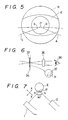
- Figure 5 shows the image observed through the observation section 4 when the eye under examination E and the apparatus are properly positioned within a horizontal plane.
- the reference symbol L designates the laser beam produced by the laser beam projection section 1 and the reference symbol A designates the light beam from the optical system 2′ built in the light receiving section 2.
- the laser beam L and the alignment beam A intersect at an angle of about 90 degrees within the horizontal plane, meaning that the cornea of the eye under examination E receives the beams at angles of 45 degrees from left and right.
- light is scattered by the cornea, as indicated by the reference symbols a and b . If the positions of the light scattering points a and b coincide with predetermined positions within the field R of the observation section 4, it is judged that the alignment of the eye under examination E and the apparatus has been achieved.
- the image observed through the observation section 4 is such as shown on the right side in Figure 9.
- the state shown on the left side of Figure 9 is the same as that shown in Figure 6 and is thus the image at the time of proper alignment.
- the state shown at the upper right is that observed when the distance between the eye E and the apparatus along the x-axis shown in Figure 7 is too short and the position of the light scattering point b becomes offset to the outside
- the state shown at the lower right is that observed when the distance between the eye E and the apparatus along the y-axis in the same figure is too short and only the light scattering point a becomes offset to the outside.
- the alignment confirmation index plate 37 that is provided at the position of one of the field stops 34 is set in position in advance, as shown in Figure 6.
- the alignment confirmation index plate 37 is constituted of, for example, optical glass and has two pairs of cross-hairs, as also shown in Figure 6.
- the alignment beam A is cut by the interference filter 17 provided in the light receiving section 2 and does not reach the photomultiplier 20, leaving the alignment light source 22 on constantly does not cause any problems.
- no interference filter 17 it suffices to turn off the alignment light source 22 when measurement is being conducted.
- a light source e.g. an LED
- a laser emitting red light it becomes easy to distinguish the scattered lights resulting from the respective beams.
- this arrangement is also useful as regards judging whether or not the measurement was carried out accurately.
- the convergence point of (for example) the green light represents the image point of the mask 19.
- the convergence point of the laser beam and the convergence point of the alignment beam A should coincide at the convergence point P (where the beams intersect at 90 degrees) and if they do not, this indicates an apparatus setting error (or a malfunction).
- the shutter S1 will close and the shutter S2 will open so that the light of the laser beam produced by the laser beam projection section 1 which is scattered by protein in the anterior chamber will enter into and be measured by the light receiving section 2, making it possible to measure the protein concentration in the anterior chamber of the eye under examination.
- a laser beam is directed from the laser beam projection section 1 to the convergence point P within the eye under examination E, while the scattered light in the vicinity of the convergence point P is received by the light receiving section 2.
- the output of the photomultiplier 20 is passed through the amplifier 21 to the counter 53 connected with the controller 51.
- the intensity of the scattered light is represented and counted as the number of pulses per unit time.
- the count data of the counter 53 namely the number of the sampling and the total count, are stored at a predetermined memory region in the memory 52 once every time unit.
- the controller 51 carries out computations on the basis of this measurement data stored in the memory 52, whereby the protein concentration in the anterior chamber is determined. As the processing for this determination is well known, it will not be explained here.
- the semiconductor laser is apt to be influenced by the ambient temperature with the result that the oscillation wavelength of the laser shifts on the order of 0.2 mm per degree Celsius with data reproducibility degraded.
- a feed-back photodiode used for laser power stabilization is also apt to be influenced by the temperature with the feeding-back output altered and with the power stability degraded.
- the semiconductor laser is, as shown in Figures 1 and 10, mounted on the housing via Peltier element 100 which is fixedly attached to the heat insulator 101.
- the Peltier element refers to an element having two different metals coupled into junction and having a so-called Peltier effect when current is applied thereto, wherein heat development or absorption proportional to the current appears at the junction.
- the Peltier element is used for temperature control in the semiconductor laser in the present embodiment.
- the heat developed in the semiconductor laser is absorbed to the Peltier element 100 via the heat absorber 101 and given off to the outside via the hosing.
- the temperature of the semiconductor laser is lower than a set value, the Peltier element 100 generate heat and make the heat absorber 101 and the semiconductor laser 5 warmer . This enables the semiconductor laser to be controlled at a temperature of 25 plus minus 1 degrees Celsius.
- the various sections of the apparatus according to the foregoing embodiment can be made compact, and the laser beam projection section 1 and the light receiving section 2 can be readily attached to the observation section 4 to combine these sections into an integrated unit.
- the laser beam projection section and the slit beam projection section are integrated in one unit and the light receiving section and the observation section are integrated in another, and since light scattered at 90 degrees to the side is employed, observation from the observation section is limited to the 90-degree direction. This makes it impossible to use the apparatus as a slit lamp microscope.
- the slit beam projection section 3 can be rotated independently of the laser beam projection section 1 and the observation section 4 to which the light receiving section 2 is attached. Therefore, the apparatus is fully utilizable as a slit lamp microscope.
- the conventional practice has been to use a beam splitter for bringing the optical axes of the slit beam and the laser beam into registration, there has been a problem of a reduction in the light quantity in the slit and laser beams.
- the loss of slit beam light is reduced by separating the slit beam projection section and the laser beam illumination section.
- the observation section 4 by separating the light receiving section 2 and the observation section 4, a brighter image can be viewed through the observation section, while making it easier to judge the alignment and observe the eye under examination.
- the observation is also facilitated by the fact that the observation section 4 can be set directly in front of the eye under examination.
- the interference filter with a peak wavelength corresponding to the wavelength of the laser beam has been inserted into the light receiving section, the measurement need not be carried out in a dark room as has been required in the past but can be conducted in a semi-dark room.
- the optical axis of the laser beam and the optical axis at the eye under examination of the optical system 2′ included in the light receiving section meet at an angle of about 90 degrees within a horizontal plane including the eye under examination E. Setting the angle at this value enables the judgment regarding alignment illustrated in Figures 5 to 9 to be made with maximum sensitivity.
- the angle of intersection between the optical axis of the laser beam and that of the optical system 2′ can be set at a value other than 90 degrees.
Landscapes
- Life Sciences & Earth Sciences (AREA)
- Health & Medical Sciences (AREA)
- Medical Informatics (AREA)
- Biophysics (AREA)
- Ophthalmology & Optometry (AREA)
- Engineering & Computer Science (AREA)
- Biomedical Technology (AREA)
- Heart & Thoracic Surgery (AREA)
- Physics & Mathematics (AREA)
- Molecular Biology (AREA)
- Surgery (AREA)
- Animal Behavior & Ethology (AREA)
- General Health & Medical Sciences (AREA)
- Public Health (AREA)
- Veterinary Medicine (AREA)
- Eye Examination Apparatus (AREA)
Applications Claiming Priority (2)
| Application Number | Priority Date | Filing Date | Title |
|---|---|---|---|
| JP1012016A JPH02193638A (ja) | 1989-01-23 | 1989-01-23 | 眼科測定装置 |
| JP12016/89 | 1989-01-23 |
Publications (2)
| Publication Number | Publication Date |
|---|---|
| EP0380221A2 true EP0380221A2 (de) | 1990-08-01 |
| EP0380221A3 EP0380221A3 (de) | 1991-03-06 |
Family
ID=11793801
Family Applications (1)
| Application Number | Title | Priority Date | Filing Date |
|---|---|---|---|
| EP19900300398 Withdrawn EP0380221A3 (de) | 1989-01-23 | 1990-01-15 | Messvorrichtung zur Augenuntersuchung |
Country Status (2)
| Country | Link |
|---|---|
| EP (1) | EP0380221A3 (de) |
| JP (1) | JPH02193638A (de) |
Cited By (2)
| Publication number | Priority date | Publication date | Assignee | Title |
|---|---|---|---|---|
| WO1993003793A1 (en) * | 1991-08-22 | 1993-03-04 | Roberto Enzo Di Biaggio | Medical light treatment apparatus |
| WO1993006770A1 (en) * | 1991-10-11 | 1993-04-15 | Candela Laser Corporation | Infrared fundus video angiography system |
Family Cites Families (6)
| Publication number | Priority date | Publication date | Assignee | Title |
|---|---|---|---|---|
| US4118563A (en) * | 1977-11-25 | 1978-10-03 | Bristol-Myers Company | Production of 7-(2-aminomethylphenylacetamido-3-(1-carboxymethyltetrazol-5-ylthiomethyl)-3-cephem-4-carboxylic acid |
| DE3431738A1 (de) * | 1984-08-29 | 1986-03-13 | Siemens AG, 1000 Berlin und 8000 München | Vorrichtung zur kuehlung eines traegers fuer wenigstens ein bauelement |
| JPS61268229A (ja) * | 1985-05-22 | 1986-11-27 | 興和株式会社 | 眼科測定装置 |
| JPS62193188A (ja) * | 1986-02-18 | 1987-08-25 | Tokyo Optical Co Ltd | 半導体レ−ザ−の発振周波数・発振出力安定化装置 |
| JPS63288134A (ja) * | 1987-05-20 | 1988-11-25 | Kowa Co | 眼科測定装置 |
| JPH024310A (ja) * | 1988-06-16 | 1990-01-09 | Kowa Co | 眼科診断方法および装置 |
-
1989
- 1989-01-23 JP JP1012016A patent/JPH02193638A/ja active Pending
-
1990
- 1990-01-15 EP EP19900300398 patent/EP0380221A3/de not_active Withdrawn
Cited By (3)
| Publication number | Priority date | Publication date | Assignee | Title |
|---|---|---|---|---|
| WO1993003793A1 (en) * | 1991-08-22 | 1993-03-04 | Roberto Enzo Di Biaggio | Medical light treatment apparatus |
| WO1993006770A1 (en) * | 1991-10-11 | 1993-04-15 | Candela Laser Corporation | Infrared fundus video angiography system |
| US5400791A (en) * | 1991-10-11 | 1995-03-28 | Candela Laser Corporation | Infrared fundus video angiography system |
Also Published As
| Publication number | Publication date |
|---|---|
| EP0380221A3 (de) | 1991-03-06 |
| JPH02193638A (ja) | 1990-07-31 |
Similar Documents
| Publication | Publication Date | Title |
|---|---|---|
| US5757462A (en) | Ophthalmic apparatus for photographing a section of an anterior part of an eye | |
| US5202708A (en) | Apparatus for photographic retroillumination image on eyeground | |
| EP0628281B1 (de) | Verfahren und Vorrichtung zur Gewinnung von Bildern der Hornhaut | |
| US4252420A (en) | Ophthalmoscopical apparatus provided with adjustment system | |
| US6494577B2 (en) | Ophthalmologic apparatus | |
| JPH1075931A (ja) | 眼底検査装置 | |
| US5013146A (en) | Opthalmological measurement apparatus | |
| US4950068A (en) | Ophthalmic disease detection apparatus | |
| EP0292216B1 (de) | Gerät zur Diagnostik von Augenleiden | |
| EP0380197B1 (de) | Opthalmologischer Apparat | |
| JP3489998B2 (ja) | 眼科装置 | |
| US5975698A (en) | Ophthalmic instrument | |
| US6164778A (en) | Corneal endothelial cell photographing apparatus | |
| JP2000245698A (ja) | 眼屈折力測定装置 | |
| EP0380221A2 (de) | Messvorrichtung zur Augenuntersuchung | |
| JPH067298A (ja) | 眼屈折計 | |
| JPH06277179A (ja) | 眼科測定装置 | |
| EP0189350B1 (de) | Gerät zur Messung der Brechkraft der Augen | |
| EP0380260A2 (de) | Messvorrichtung zur Augenuntersuchung | |
| JP3518927B2 (ja) | 眼科装置 | |
| JP3015042B2 (ja) | 手持ち眼屈折計 | |
| JPH09108185A (ja) | 眼科装置 | |
| JP5522629B2 (ja) | 眼底撮影装置 | |
| JP3211977B2 (ja) | 眼科装置 | |
| JP4700785B2 (ja) | 眼科装置 |
Legal Events
| Date | Code | Title | Description |
|---|---|---|---|
| PUAI | Public reference made under article 153(3) epc to a published international application that has entered the european phase |
Free format text: ORIGINAL CODE: 0009012 |
|
| AK | Designated contracting states |
Kind code of ref document: A2 Designated state(s): CH DE FR GB IT LI |
|
| PUAL | Search report despatched |
Free format text: ORIGINAL CODE: 0009013 |
|
| AK | Designated contracting states |
Kind code of ref document: A3 Designated state(s): CH DE FR GB IT LI |
|
| 17P | Request for examination filed |
Effective date: 19910813 |
|
| 17Q | First examination report despatched |
Effective date: 19930831 |
|
| STAA | Information on the status of an ep patent application or granted ep patent |
Free format text: STATUS: THE APPLICATION IS DEEMED TO BE WITHDRAWN |
|
| 18D | Application deemed to be withdrawn |
Effective date: 19940111 |