EP0376900A1 - Brennkraftmaschine mit mehreren Zylindern, insbesondere für Kraftwagen - Google Patents
Brennkraftmaschine mit mehreren Zylindern, insbesondere für Kraftwagen Download PDFInfo
- Publication number
- EP0376900A1 EP0376900A1 EP89830550A EP89830550A EP0376900A1 EP 0376900 A1 EP0376900 A1 EP 0376900A1 EP 89830550 A EP89830550 A EP 89830550A EP 89830550 A EP89830550 A EP 89830550A EP 0376900 A1 EP0376900 A1 EP 0376900A1
- Authority
- EP
- European Patent Office
- Prior art keywords
- block
- sump
- main bearing
- bearing caps
- cylinder block
- Prior art date
- Legal status (The legal status is an assumption and is not a legal conclusion. Google has not performed a legal analysis and makes no representation as to the accuracy of the status listed.)
- Granted
Links
Images


Classifications
-
- F—MECHANICAL ENGINEERING; LIGHTING; HEATING; WEAPONS; BLASTING
- F02—COMBUSTION ENGINES; HOT-GAS OR COMBUSTION-PRODUCT ENGINE PLANTS
- F02F—CYLINDERS, PISTONS OR CASINGS, FOR COMBUSTION ENGINES; ARRANGEMENTS OF SEALINGS IN COMBUSTION ENGINES
- F02F7/00—Casings, e.g. crankcases or frames
- F02F7/0002—Cylinder arrangements
- F02F7/0007—Crankcases of engines with cylinders in line
-
- F—MECHANICAL ENGINEERING; LIGHTING; HEATING; WEAPONS; BLASTING
- F02—COMBUSTION ENGINES; HOT-GAS OR COMBUSTION-PRODUCT ENGINE PLANTS
- F02F—CYLINDERS, PISTONS OR CASINGS, FOR COMBUSTION ENGINES; ARRANGEMENTS OF SEALINGS IN COMBUSTION ENGINES
- F02F1/00—Cylinders; Cylinder heads
- F02F1/002—Integrally formed cylinders and cylinder heads
-
- F—MECHANICAL ENGINEERING; LIGHTING; HEATING; WEAPONS; BLASTING
- F02—COMBUSTION ENGINES; HOT-GAS OR COMBUSTION-PRODUCT ENGINE PLANTS
- F02F—CYLINDERS, PISTONS OR CASINGS, FOR COMBUSTION ENGINES; ARRANGEMENTS OF SEALINGS IN COMBUSTION ENGINES
- F02F7/00—Casings, e.g. crankcases or frames
- F02F7/0043—Arrangements of mechanical drive elements
- F02F7/0053—Crankshaft bearings fitted in the crankcase
-
- F—MECHANICAL ENGINEERING; LIGHTING; HEATING; WEAPONS; BLASTING
- F02—COMBUSTION ENGINES; HOT-GAS OR COMBUSTION-PRODUCT ENGINE PLANTS
- F02B—INTERNAL-COMBUSTION PISTON ENGINES; COMBUSTION ENGINES IN GENERAL
- F02B1/00—Engines characterised by fuel-air mixture compression
- F02B1/02—Engines characterised by fuel-air mixture compression with positive ignition
- F02B1/04—Engines characterised by fuel-air mixture compression with positive ignition with fuel-air mixture admission into cylinder
-
- F—MECHANICAL ENGINEERING; LIGHTING; HEATING; WEAPONS; BLASTING
- F02—COMBUSTION ENGINES; HOT-GAS OR COMBUSTION-PRODUCT ENGINE PLANTS
- F02B—INTERNAL-COMBUSTION PISTON ENGINES; COMBUSTION ENGINES IN GENERAL
- F02B75/00—Other engines
- F02B75/16—Engines characterised by number of cylinders, e.g. single-cylinder engines
- F02B75/18—Multi-cylinder engines
- F02B2075/1804—Number of cylinders
- F02B2075/1816—Number of cylinders four
-
- F—MECHANICAL ENGINEERING; LIGHTING; HEATING; WEAPONS; BLASTING
- F02—COMBUSTION ENGINES; HOT-GAS OR COMBUSTION-PRODUCT ENGINE PLANTS
- F02B—INTERNAL-COMBUSTION PISTON ENGINES; COMBUSTION ENGINES IN GENERAL
- F02B2275/00—Other engines, components or details, not provided for in other groups of this subclass
- F02B2275/20—SOHC [Single overhead camshaft]
-
- F—MECHANICAL ENGINEERING; LIGHTING; HEATING; WEAPONS; BLASTING
- F02—COMBUSTION ENGINES; HOT-GAS OR COMBUSTION-PRODUCT ENGINE PLANTS
- F02F—CYLINDERS, PISTONS OR CASINGS, FOR COMBUSTION ENGINES; ARRANGEMENTS OF SEALINGS IN COMBUSTION ENGINES
- F02F1/00—Cylinders; Cylinder heads
- F02F2001/008—Stress problems, especially related to thermal stress
Definitions
- the present invention relates in general to multi-cylinder internal combustion engines, particularly for motor vehicles.
- the intake and exhaust manifolds and the covers are also fixed to the block and to the head by means of bolts and gaskets.
- the connections between the various components are achieved by means of flanges which are not always in one piece.
- the flange for attaching the oil sump normally carries "cradles" which give rise to oil leaks.
- the structural deterioration of the materials, due to ageing and to thermal stress, or the incomplete tightening of the bolts connecting the various components are the cause of defects and breakdowns.
- the object of the present invention is to provide an engine with a novel architecture, which is formed so as to eliminate fluid leakages, to reduce components which are most subject to defects due to assembly anomalies or structural deterioration, and to rationalise the function of each component and minimise the use of nuts and bolts in order to produce a very strong and reliable unit.
- a multi-cylinder internal combustion engine including a cylinder block in which are formed the cylinders, an oil sump situated beneath the block, combustion chambers for the cylinders, intake and exhaust ducts, seats for valves and spark plugs, and a timing control assembly situated above the block, and a crankshaft supported for rotation by means of main bearings and main bearing caps, characterised in that: - the cylinder block is a single piece which incorporates the combustion chambers, the ducts and the seats and, above the latter and substantially in correspondence with the lower ends of the cylinders, is formed with two continuous integral flanges, in a single upper plane and a single lower plane respectively, for the coupling of corresponding continuous integral flanges formed in single planes and integral with the timing control assembly and the oil sump respectively, - the oil sump is constituted by a structural body for supporting the crankshaft, which is formed in one piece with the main bearings and is provided with tubular lateral pillars for housing bolts for
- this concept affords notable advantages in terms of the bending and torsional strength of the engine and of the reduction of its tendency to vibrate and of the leakage of fluids to the outside.
- the spacer means conveniently comprise spacers of calibrated thickness which are interposed between the mutually facing surfaces of the main bearing caps and the retaining feet of the block and are held on the caps by means of resilient bridge members formed integrally with the spacers and provided with parts for engaging complementary fixing recesses in the caps.
- the main bearing caps have lateral projections which bear against complementary lateral shoulders of the lateral pillars of the sump.
- the sump has box-like front and rear walls provided with respective apertures for the drive from the driving shaft, the front one being formed with a flange which constitutes a seat for the oil pump and the rear one defining a seat for the rear seal of the driving shaft.
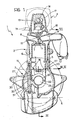
- a four-cylinder internal combustion engine for a motor car is generally indicated 1.
- the engine 1 is composed essentially of three elements: a cylinder block 2, a sump structure 3 fitted beneath the block 2, and a timing control assembly 4 fitted above the block 2.
- the block 2 is constituted by a single piece defining the four cylinders 5, a chamber 6 for the circulation of the coolant liquid for the engine 1, as well as all the parts which are formed in the cylinder head in conventional engines, that is, the combustion chambers 7 of the cylinders 5, their intake ducts 8 and exhaust ducts 9, the seats 10 for the inlet and exhaust valves 11 and their springs, and the seats for any spark plugs (not illustrated).
- the chamber 6 for the coolant of the engine which is wholly included in the one-piece casting of the block 2, communicates with the outside on one side through a seat, not shown, for the pump for the liquid and on the other side through a lateral connector 12, which is also integral with the block 2 and acts as the casing for a thermostat 13 for regulating the temperature of the coolant liquid.
- the engine block 2 is formed with two continuous integral flanges, an upper flange 14 and a lower flange 15, each in a single plane.
- the upper flange 14 is coupled to a corresponding continuous flange 16 formed in a single plane and integral with the timing control assembly 4, which is constituted essentially by a body 17 containing the camshaft 18 and the tappets, schematically indicated 19.
- the lower flange 15 is situated substantially at the level of the lower ends of the cylinders 5 and is coupled to a corresponding continuous flange formed in a single plane 20 and integral with the sump structure 3.
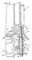
- the sump 3 is box-like on three sides and on its front and rear faces. These faces define two coaxial holes 21, 22 in correspondence with which an annular flange 23 for the attachment of the oil pump (not shown) and an annular seat 24 for the rear seal of the driving shaft 25 are formed, respectively.
- the driving shaft 25 (which is inserted from above during assembly) is supported by the sump structure 3 by means of main bearings 26 which are integral therewith, and main bearing caps 27 which bear on the sump 3 and are clamped against it by the block 2 in the manner made clear below.
- pistons 29 are sealingly slidable in the respective cylinders 5 and are connected to the crankshaft 25 in conventional manner, by means of connecting rods 28.
- the sump 3 is connected to the block 2 by means of axial bolts 30 ( Figures 1 and 4) inserted in tubular pillars 31 formed integrally with the sump 3 beside the main bearing caps 26.
- the sump 3/block 2 assembly thus forms an egg-shaped chamber which has very high bending and torsional strength and is insensitive to vibrations.
- the sump 3 also acts as a reservoir for the lubricating oil and contains all the ducts which take the oil to the pump and thence to the filter and the crankshaft bearings, indicated 32.
- the function of the reservoir for the lubricating oil may be carried out by a lower sump bolted to the sump structure, with continuous integral flanges lying in a single plane for the coupling of the sump and the lower sump.
- the plane is, for example, the one identified by the line A in Figure 1.
- each main bearing cap 27 simply bears on the respective main bearing 26 and is aligned therewith by means of centring pins 33.
- Each main bearing cap has at least two separate appendages 34 which face the block 2 and are situated opposite corresponding feet 35 thereof.
- Spacers 36 of calibrated thickness are interposed between the mutually facing surfaces of the appendages 34 and the corresponding feet 35.
- the two spacers 36 associated with each main bearing cap 27 are formed integrally with a resilient plate-shaped bridge member 37 provided with side parts 38 for engaging complementary fixing recesses 39 in the main bearing cap 27.
- the engine according to the invention achieves a considerable structural simplification as a result of the reduction of the number of components and the minimising of the use of nuts and bolts. Moreover, the elimination of parts and materials which are subject to ageing enables the risks of liquid and gas leakages to be eliminated, leading to the production of an extremely strong and reliable unit.
Applications Claiming Priority (2)
| Application Number | Priority Date | Filing Date | Title |
|---|---|---|---|
| IT6817788 | 1988-12-30 | ||
| IT68177/88A IT1224051B (it) | 1988-12-30 | 1988-12-30 | Motore a combustione interna pluri cilindrico particolarmente per autoveicoli |
Publications (2)
| Publication Number | Publication Date |
|---|---|
| EP0376900A1 true EP0376900A1 (de) | 1990-07-04 |
| EP0376900B1 EP0376900B1 (de) | 1993-07-07 |
Family
ID=11308349
Family Applications (1)
| Application Number | Title | Priority Date | Filing Date |
|---|---|---|---|
| EP89830550A Expired - Lifetime EP0376900B1 (de) | 1988-12-30 | 1989-12-19 | Brennkraftmaschine mit mehreren Zylindern, insbesondere für Kraftwagen |
Country Status (5)
| Country | Link |
|---|---|
| EP (1) | EP0376900B1 (de) |
| BR (1) | BR8906870A (de) |
| DE (1) | DE68907474T2 (de) |
| ES (1) | ES2042070T3 (de) |
| IT (1) | IT1224051B (de) |
Cited By (3)
| Publication number | Priority date | Publication date | Assignee | Title |
|---|---|---|---|---|
| FR2668202A1 (fr) * | 1990-10-23 | 1992-04-24 | Daimler Benz Ag | Carter d'un moteur a combustion interne a pistons alternatifs. |
| EP0825339A1 (de) * | 1996-08-20 | 1998-02-25 | Dr.Ing.h.c. F. Porsche Aktiengesellschaft | Zylinderblock einer Brennkraftmaschine |
| FR2858360A1 (fr) * | 2003-07-24 | 2005-02-04 | Honda Motor Co Ltd | Moteur a refroidissement liquide |
Citations (4)
| Publication number | Priority date | Publication date | Assignee | Title |
|---|---|---|---|---|
| FR862709A (fr) * | 1938-09-10 | 1941-03-13 | Maschf Augsburg Nuernberg Ag | Moteur à combustion interne construit en métal léger |
| GB1040793A (en) * | 1964-04-10 | 1966-09-01 | British Aluminium Co Ltd | Improvements in or relating to internal combustion engines |
| AT376018B (de) * | 1975-09-04 | 1984-10-10 | List Hans | Wassergekuehlte brennkraftmaschine |
| DE3801715A1 (de) * | 1987-01-21 | 1988-08-04 | Mazda Motor | Fahrzeugmotoranordnung |
-
1988
- 1988-12-30 IT IT68177/88A patent/IT1224051B/it active
-
1989
- 1989-12-19 ES ES198989830550T patent/ES2042070T3/es not_active Expired - Lifetime
- 1989-12-19 DE DE89830550T patent/DE68907474T2/de not_active Expired - Lifetime
- 1989-12-19 EP EP89830550A patent/EP0376900B1/de not_active Expired - Lifetime
- 1989-12-27 BR BR898906870A patent/BR8906870A/pt not_active IP Right Cessation
Patent Citations (4)
| Publication number | Priority date | Publication date | Assignee | Title |
|---|---|---|---|---|
| FR862709A (fr) * | 1938-09-10 | 1941-03-13 | Maschf Augsburg Nuernberg Ag | Moteur à combustion interne construit en métal léger |
| GB1040793A (en) * | 1964-04-10 | 1966-09-01 | British Aluminium Co Ltd | Improvements in or relating to internal combustion engines |
| AT376018B (de) * | 1975-09-04 | 1984-10-10 | List Hans | Wassergekuehlte brennkraftmaschine |
| DE3801715A1 (de) * | 1987-01-21 | 1988-08-04 | Mazda Motor | Fahrzeugmotoranordnung |
Cited By (5)
| Publication number | Priority date | Publication date | Assignee | Title |
|---|---|---|---|---|
| FR2668202A1 (fr) * | 1990-10-23 | 1992-04-24 | Daimler Benz Ag | Carter d'un moteur a combustion interne a pistons alternatifs. |
| EP0825339A1 (de) * | 1996-08-20 | 1998-02-25 | Dr.Ing.h.c. F. Porsche Aktiengesellschaft | Zylinderblock einer Brennkraftmaschine |
| US5842447A (en) * | 1996-08-20 | 1998-12-01 | Dr. Ing. H.C.F. Porsche Ag | Cylinder block of an internal-combustion engine |
| FR2858360A1 (fr) * | 2003-07-24 | 2005-02-04 | Honda Motor Co Ltd | Moteur a refroidissement liquide |
| US7069898B2 (en) | 2003-07-24 | 2006-07-04 | Honda Motor Co., Ltd. | Liquid-cooled engine |
Also Published As
| Publication number | Publication date |
|---|---|
| IT1224051B (it) | 1990-09-26 |
| DE68907474T2 (de) | 1993-10-21 |
| ES2042070T3 (es) | 1993-12-01 |
| BR8906870A (pt) | 1990-09-25 |
| DE68907474D1 (de) | 1993-08-12 |
| EP0376900B1 (de) | 1993-07-07 |
| IT8868177A0 (it) | 1988-12-30 |
Similar Documents
| Publication | Publication Date | Title |
|---|---|---|
| US4438733A (en) | Air cooled internal combustion engine | |
| US5458099A (en) | Cylinder head arrangement of an internal-combustion engine | |
| US6484683B2 (en) | Rocker carrier | |
| US4708105A (en) | Chamber construction for internal combustion engine | |
| CN102536496B (zh) | 气缸体总成 | |
| US4377993A (en) | Internal combustion engine | |
| US6279519B1 (en) | Air and water cooled opposed cylinder aircraft engine | |
| EP0376900B1 (de) | Brennkraftmaschine mit mehreren Zylindern, insbesondere für Kraftwagen | |
| US4699100A (en) | Chamber construction for internal combustion engine | |
| US5341781A (en) | Reduced component internal combustion engine | |
| GB2127896A (en) | Engine with side wall mounted vibration isolated manifold | |
| US3527263A (en) | Rocker shaft support with fuel nozzle supporting means | |
| US10202938B2 (en) | Welded engine block for small internal combustion engines | |
| US9581106B2 (en) | Welded engine block for small internal combustion engines | |
| US4748948A (en) | Internal combustion engine for motor vehicles | |
| GB2172061A (en) | A crankshaft supporting structure | |
| US4898134A (en) | Crankcase seal arrangement for two cycle engine | |
| JP2686644B2 (ja) | エンジンの主軸受フレーム構造 | |
| US6279515B1 (en) | Coolant pump chamber cover with ignition module supports | |
| JPH02286822A (ja) | V形エンジンの給気装置 | |
| WO2016093997A1 (en) | Welded engine block for small internal combustion engines | |
| JP2631014B2 (ja) | V形エンジンの冷却装置 | |
| JP3320081B2 (ja) | 多気筒エンジン | |
| GB563790A (en) | Improvements in or relating to the construction of internal combustion engines | |
| KR19980029115A (ko) | 자동차 v형 엔진의 흡기매니폴드와 서지탱크 기밀구 |
Legal Events
| Date | Code | Title | Description |
|---|---|---|---|
| PUAI | Public reference made under article 153(3) epc to a published international application that has entered the european phase |
Free format text: ORIGINAL CODE: 0009012 |
|
| AK | Designated contracting states |
Kind code of ref document: A1 Designated state(s): DE ES FR GB SE |
|
| 17P | Request for examination filed |
Effective date: 19900711 |
|
| 17Q | First examination report despatched |
Effective date: 19911023 |
|
| GRAA | (expected) grant |
Free format text: ORIGINAL CODE: 0009210 |
|
| AK | Designated contracting states |
Kind code of ref document: B1 Designated state(s): DE ES FR GB SE |
|
| REF | Corresponds to: |
Ref document number: 68907474 Country of ref document: DE Date of ref document: 19930812 |
|
| ET | Fr: translation filed | ||
| PGFP | Annual fee paid to national office [announced via postgrant information from national office to epo] |
Ref country code: GB Payment date: 19931116 Year of fee payment: 5 |
|
| PGFP | Annual fee paid to national office [announced via postgrant information from national office to epo] |
Ref country code: SE Payment date: 19931117 Year of fee payment: 5 |
|
| PGFP | Annual fee paid to national office [announced via postgrant information from national office to epo] |
Ref country code: DE Payment date: 19931122 Year of fee payment: 5 |
|
| REG | Reference to a national code |
Ref country code: ES Ref legal event code: FG2A Ref document number: 2042070 Country of ref document: ES Kind code of ref document: T3 |
|
| PGFP | Annual fee paid to national office [announced via postgrant information from national office to epo] |
Ref country code: ES Payment date: 19931203 Year of fee payment: 5 |
|
| PLBE | No opposition filed within time limit |
Free format text: ORIGINAL CODE: 0009261 |
|
| STAA | Information on the status of an ep patent application or granted ep patent |
Free format text: STATUS: NO OPPOSITION FILED WITHIN TIME LIMIT |
|
| 26N | No opposition filed | ||
| PG25 | Lapsed in a contracting state [announced via postgrant information from national office to epo] |
Ref country code: GB Effective date: 19941219 |
|
| PG25 | Lapsed in a contracting state [announced via postgrant information from national office to epo] |
Ref country code: SE Effective date: 19941220 Ref country code: ES Free format text: LAPSE BECAUSE OF EXPIRATION OF PROTECTION Effective date: 19941220 |
|
| EAL | Se: european patent in force in sweden |
Ref document number: 89830550.3 |
|
| GBPC | Gb: european patent ceased through non-payment of renewal fee |
Effective date: 19941219 |
|
| PG25 | Lapsed in a contracting state [announced via postgrant information from national office to epo] |
Ref country code: DE Effective date: 19950901 |
|
| EUG | Se: european patent has lapsed |
Ref document number: 89830550.3 |
|
| PGFP | Annual fee paid to national office [announced via postgrant information from national office to epo] |
Ref country code: FR Payment date: 19981230 Year of fee payment: 10 |
|
| PG25 | Lapsed in a contracting state [announced via postgrant information from national office to epo] |
Ref country code: FR Free format text: LAPSE BECAUSE OF NON-PAYMENT OF DUE FEES Effective date: 20000831 |
|
| REG | Reference to a national code |
Ref country code: FR Ref legal event code: ST |
|
| REG | Reference to a national code |
Ref country code: ES Ref legal event code: FD2A Effective date: 20010301 |