US4898134A - Crankcase seal arrangement for two cycle engine - Google Patents
Crankcase seal arrangement for two cycle engine Download PDFInfo
- Publication number
- US4898134A US4898134A US07/316,154 US31615489A US4898134A US 4898134 A US4898134 A US 4898134A US 31615489 A US31615489 A US 31615489A US 4898134 A US4898134 A US 4898134A
- Authority
- US
- United States
- Prior art keywords
- crankcase
- semi
- defining
- cylindrical surface
- shoulder
- Prior art date
- Legal status (The legal status is an assumption and is not a legal conclusion. Google has not performed a legal analysis and makes no representation as to the accuracy of the status listed.)
- Expired - Lifetime
Links
- 238000007789 sealing Methods 0.000 claims abstract description 40
- 238000002485 combustion reaction Methods 0.000 claims description 15
- 230000013011 mating Effects 0.000 claims description 6
- 238000010276 construction Methods 0.000 description 5
- 239000012530 fluid Substances 0.000 description 2
- 238000003754 machining Methods 0.000 description 1
- 230000035945 sensitivity Effects 0.000 description 1
Images
Classifications
-
- F—MECHANICAL ENGINEERING; LIGHTING; HEATING; WEAPONS; BLASTING
- F16—ENGINEERING ELEMENTS AND UNITS; GENERAL MEASURES FOR PRODUCING AND MAINTAINING EFFECTIVE FUNCTIONING OF MACHINES OR INSTALLATIONS; THERMAL INSULATION IN GENERAL
- F16J—PISTONS; CYLINDERS; SEALINGS
- F16J15/00—Sealings
- F16J15/54—Other sealings for rotating shafts
-
- F—MECHANICAL ENGINEERING; LIGHTING; HEATING; WEAPONS; BLASTING
- F02—COMBUSTION ENGINES; HOT-GAS OR COMBUSTION-PRODUCT ENGINE PLANTS
- F02F—CYLINDERS, PISTONS OR CASINGS, FOR COMBUSTION ENGINES; ARRANGEMENTS OF SEALINGS IN COMBUSTION ENGINES
- F02F7/00—Casings, e.g. crankcases or frames
- F02F7/0021—Construction
- F02F7/0036—Casings for two-stroke engines with scavenging conduits
-
- F—MECHANICAL ENGINEERING; LIGHTING; HEATING; WEAPONS; BLASTING
- F16—ENGINEERING ELEMENTS AND UNITS; GENERAL MEASURES FOR PRODUCING AND MAINTAINING EFFECTIVE FUNCTIONING OF MACHINES OR INSTALLATIONS; THERMAL INSULATION IN GENERAL
- F16J—PISTONS; CYLINDERS; SEALINGS
- F16J9/00—Piston-rings, e.g. non-metallic piston-rings, seats therefor; Ring sealings of similar construction
- F16J9/12—Details
- F16J9/14—Joint-closures
- F16J9/16—Joint-closures obtained by stacking of rings
-
- F—MECHANICAL ENGINEERING; LIGHTING; HEATING; WEAPONS; BLASTING
- F02—COMBUSTION ENGINES; HOT-GAS OR COMBUSTION-PRODUCT ENGINE PLANTS
- F02B—INTERNAL-COMBUSTION PISTON ENGINES; COMBUSTION ENGINES IN GENERAL
- F02B75/00—Other engines
- F02B75/02—Engines characterised by their cycles, e.g. six-stroke
- F02B2075/022—Engines characterised by their cycles, e.g. six-stroke having less than six strokes per cycle
- F02B2075/025—Engines characterised by their cycles, e.g. six-stroke having less than six strokes per cycle two
Definitions
- the invention relates generally to internal combustion engines and, more particularly, to two stroke internal combustion engines in which each cylinder has associated therewith a separate individual crankcase.
- crankcases have been sealed against loss of pressure by preventing fluid flow from the crankcases and between the crankshaft and the engine block and crankcase cover by use of a single sealing member between a crankshift disc and a cylindrical surface formed by the engine block and by a crankcase cover.
- the engine block and crankcase cover were manufactured with relatively tight tolerances and the engine block and crankcase covers were individually selected for marriage with each other to produce, as nearly as practical as possible, an annular concentric cylindrical sealing surface adapted to cooperate with a single sealing member carried in a groove on the crankcase disc.
- the invention provides an internal combustion engine comprising an engine block comprising a first crankcase-defining member including a first semi-cylindrical surface extending about a first center, and also including a first shoulder extending from the first semi-cylindrical surface, a second crankcase-defining member fixedly connected to the first crankcase defining member and including a second semi-cylindrical surface located in generally co-planar facing relation to the first semi-cylindrical surface, and extending about a second center located in spaced relation to the first center, and also including a second shoulder extending from the second semi-cylindrical surface, a crankshaft supported by the engine block and including a crankcase-defining disc including a cylindrical surface in spaced and generally co-planar facing relation to the first and second semi-cylindrical surfaces and including therein an annular groove, a first seal member located in the annular groove and having an outer surface in sealing engagement with the semi-cylindrical surface of one of the first and second crankcase-defining members and
- the first crankcase-defining member includes a first flat surface which extends from the first semi-cylindrical surface and which defines the first shoulder
- the second crankcase-defining member includes a second flat surface which extends from the second semi-cylindrical surface and which defines the second shoulder
- the first and second flat surfaces are sealingly engaged with each other
- the first and second centers are located in the plane of engagement of the first and second flat surfaces.
- the invention also provides an internal combustion engine comprising an engine block comprising a first crankcase-defining member including a first semi-cylindrical surface having an end and extending about a first center, and also including a first mating surface extending from the first semi-cylindrical surface and defining a first shoulder, a second crankcase-defining member fixedly connected to the first crankcase defining member and including a second semi-cylindrical surface having an end, and extending about a second center and also including a second mating surface extending from the second semi-cylindrical surface and defining a second shoulder, and means fixedly connecting together the first and second crankcase-defining members with the first and second flat surfaces in mating engagement in a plane of engagement, and with the first and second centers in spaced relation in the plane, and with the first and second semi-cylindrical surfaces in generally co-planar facing relation to each other.
- the invention also provides an internal combustion engine including an engine block comprising a first crankcase-defining member including a first semi-cylindrical surface extending about a first center, and also including a first shoulder extending from the first semi-cylindrical surface, a second crankcase-defining member fixedly connected to said first crankcase-defining member and including a second semi-cylindrical surface located in generally co-planar facing relation to the first semi-cylindrical surface, and extending about a second center located in spaced relation to the first center, and also including a second shoulder extending from the second semi-cylindrical surface, a crankshaft supported by the engine block and including a crankcase-defining disc including a cylindrical surface in spaced and generally co-planar facing relation to the first and second semi-cylindrical surfaces and including therein an annular groove having spaced parallel first and second side surfaces, a first seal member located in the annular groove and comprising a first split washer having a first side surface in sealing engagement with one of the first
- one of the first and second crankcase-defining members is fabricated of plastic.
- FIG. 1 is a partially schematic and partially sectioned view of a portion of an internal combustion engine embodying various of the features of the invention.
- FIG. 1 fragmentarily illustrates a crankcase defining seal provided by the invention.
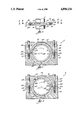
- FIG. 2 is an enlarged sectional view taken along line 2--2 of FIG. 1.
- FIG. 3 is an enlarged sectional view taken along line 3--3 of FIG. 1.
- an internal combustion engine 11 including an engine block defining one or more cylinders (not shown) and comprising (See FIGS. 2 and 3) a first crankcase-defining member 13 including a semi-cylindrical surface 15 extending at a first radius about a first center 17 and having ends 19 and 21 terminating in a first flat surface 23 constituting, in part, a sealing surface for engagement with a crankcase cover.
- the engine 11 also includes the just mentioned crankcase cover which comprises a second crankcase-defining member 25 including a second semi-cylindrical surface 27 located in generally co-planar relation to the first semi-cylindrical surface 15 and extending at a second radius equal to said first radius and about a second center 29 in spaced relation to said first center 17 and having ends 31 and 33 terminating in a second flat surface 35 which constitutes, in part, a sealing surface for engagement with the flat surface 23 of the first crankcase-defining member 13, either with or without an intervening gasket (not shown).
- a second crankcase-defining member 25 including a second semi-cylindrical surface 27 located in generally co-planar relation to the first semi-cylindrical surface 15 and extending at a second radius equal to said first radius and about a second center 29 in spaced relation to said first center 17 and having ends 31 and 33 terminating in a second flat surface 35 which constitutes, in part, a sealing surface for engagement with the flat surface 23 of the first crankcase-defining member 13,
- the engine 11 also includes means for fixedly assembling the first and second crankcase-defining members 13 and 25 to each other with the first and second flat surfaces 23 an 35 in engagement with each other (with or without an intervening gasket) and with said first and second centers 17 and 29 being offset or spaced from each other in the plane of the engagement of the first and second flat surfaces 23 and 35 so as to thereby define a first shoulder 41 at the end 19 of the first semi-cylindrical surface 15 and a second shoulder 43 at the end 33 of the second semi-cylindrical surface 27. While other constructions can be employed, in the disclosed construction, such means comprises a plurality of bolts 45.
- the engine 11 also includes a crankshaft 61 which can be suitably supported by one or both of the crankcase-defining members 13 and 25, such as by suitable journals or bearings (not shown).
- the crankshaft 61 includes one or more discs 63 (only one of which is shown) which serve to assist in defining one or more crankcases so that each cylinder has associated therewith its own individual and separate crankcase.
- the discs 63 can also serve as counter-weights.
- Each of the discs 63 includes an outer cylindrical surface 65 in facing generally co-planar relation to the semi-cylindrical surfaces 15 and 27 of the first and second crankcase-defining members 13 and 25.
- annular groove 67 which has spaced side surfaces 69 and 71.
- the engine 11 also includes (See FIG. 2) a first sealing member in the form of an annular split washer 81 which is located in the annular groove 67, which has a first side surface 83 sealingly engagable with the side surface 69 of the groove 67, a second side surface 85, an outer generally cylindrical surface 87 in close sealing engagement with at least a portion of the semi-cylindrical surface 15 of first crankcase-defining member 13, and an end 89 engaging the shoulder 43 on the second crankcase-defining member 25 to prevent rotation of the first sealing member or split washer 81 relative to the crankcase-defining members 13 and 25 in response to rotation of the crankshaft 61 in the clockwise direction as shown in FIGS. 2 and 3.
- a first sealing member in the form of an annular split washer 81 which is located in the annular groove 67, which has a first side surface 83 sealingly engagable with the side surface 69 of the groove 67, a second side surface 85, an outer generally cylindrical surface 87 in close sealing engagement with at least
- the engine 11 also includes (See FIG. 2) a second sealing member in the form of an annular split washer 91 which is located in the annular groove 67, which has a first side surface 93 sealingly engagable with the the side surface 71 of the groove 67, a second side surface 95 sealingly engagable with the second side surface 85 of the first split washer 81, an outer generally cylindrical surface 97 sealingly engagable with at least a portion of the semi-cylindrical surface 27 of the second crankcase-defining member 25, and an end 99 engaging the shoulder 41 on the first crankcase-defining member 13 to prevent rotation of the second sealing member or split washer 91 relative to the crankcase-defining members 13 and 25 in response to rotation of the crankshaft 61 in the clockwise direction as shown in FIGS. 2 and 3.
- a second sealing member in the form of an annular split washer 91 which is located in the annular groove 67, which has a first side surface 93 sealingly engagable with the the side surface 71 of the groove
- the sealing members 81 and 91 engage each other, and the groove side walls 69 and 71, and the crankcase defining members 13 and 25 to substantially prevent fluid flow from the individual crankcases and between the crankshaft 61 and the crankcase-defining members 13 and 25.
- the use of the disclosed construction advantageously avoids the expense of marrying a specific crankcase cover to a specific engine block in order to obtain an essentially cylindrical sealing surface for location in spaced relation to a crankcase disc. Accordingly, expensive machining is avoided and tolerance sensitivity can be less severe.
- the crankcase cover or second crankcase-defining member 27 can be fabricated of plastic. Consequently, the cost of sealing and defining the individual crankcases is much reduced.
Abstract
Description
______________________________________
2,885,249     Payne      May 5, 1959
2,356,377     Voitik     December 5, 1967
3,455,565     Jepsen     July 15, 1969
4,615,531     Green      October 7, 1986
______________________________________
Claims (8)
Priority Applications (2)
| Application Number | Priority Date | Filing Date | Title |
|---|---|---|---|
| US07/316,154 US4898134A (en) | 1989-02-27 | 1989-02-27 | Crankcase seal arrangement for two cycle engine |
| JP2045344A JPH02241955A (en) | 1989-02-27 | 1990-02-26 | Crank case seal means for 2-cycle engine |
Applications Claiming Priority (1)
| Application Number | Priority Date | Filing Date | Title |
|---|---|---|---|
| US07/316,154 US4898134A (en) | 1989-02-27 | 1989-02-27 | Crankcase seal arrangement for two cycle engine |
Publications (1)
| Publication Number | Publication Date |
|---|---|
| US4898134A true US4898134A (en) | 1990-02-06 |
Family
ID=23227733
Family Applications (1)
| Application Number | Title | Priority Date | Filing Date |
|---|---|---|---|
| US07/316,154 Expired - Lifetime US4898134A (en) | 1989-02-27 | 1989-02-27 | Crankcase seal arrangement for two cycle engine |
Country Status (2)
| Country | Link |
|---|---|
| US (1) | US4898134A (en) |
| JP (1) | JPH02241955A (en) |
Cited By (3)
| Publication number | Priority date | Publication date | Assignee | Title |
|---|---|---|---|---|
| US5239864A (en) * | 1991-04-01 | 1993-08-31 | The United States Of America As Represented By The Administrator Of The National Aeronautics And Space Administration | Dynamic tester for rotor seals and bearings |
| US5265566A (en) * | 1991-12-23 | 1993-11-30 | General Motors Corporation | Assembled seal disc for a crankshaft |
| US5645358A (en) * | 1996-10-30 | 1997-07-08 | The Torrington Company | Antifriction bearing with a seal locked against rotation |
Citations (12)
| Publication number | Priority date | Publication date | Assignee | Title |
|---|---|---|---|---|
| US2885249A (en) * | 1958-04-28 | 1959-05-05 | Dresser Operations Inc | High pressure piston ring assembly |
| US3356377A (en) * | 1965-08-13 | 1967-12-05 | Continental Illinois Nat Bank | Fluid sealing assembly with resilient sealing rings |
| US3455565A (en) * | 1964-07-29 | 1969-07-15 | Air Prod & Chem | Piston rings |
| US3917286A (en) * | 1973-09-14 | 1975-11-04 | Caterpillar Tractor Co | Lip seal assembly for crankshafts |
| US3941396A (en) * | 1974-08-15 | 1976-03-02 | Caterpillar Tractor Co. | Seal for rotating means |
| US4013298A (en) * | 1976-02-23 | 1977-03-22 | Caterpillar Tractor Co. | Dynamic air bearing seal for engine crankshaft |
| US4320724A (en) * | 1979-04-16 | 1982-03-23 | Kawasaki Jukogyo Kabushiki Kaisha | Inter-crankchamber sealing means for multiple cylinder two stroke engines |
| US4615531A (en) * | 1985-02-19 | 1986-10-07 | Green George D | Double ring piston sealing arrangement |
| US4645215A (en) * | 1985-01-15 | 1987-02-24 | Firma Carl Freudenberg | Shaft and radially sealing ring with cold flexed seal disk and a method of its use for sealing the crankshaft of a two-cycle engine |
| US4667967A (en) * | 1985-10-04 | 1987-05-26 | Goetze Ag | Shaft sealing system with lip and labyrinth seals |
| US4693216A (en) * | 1984-07-17 | 1987-09-15 | Dr. Ing. H.C.F. Porsche Aktiengesellschaft | Crankshaft bearings for internal-combustion engines |
| US4753201A (en) * | 1984-12-06 | 1988-06-28 | Honda Giken Kogyo Kabushiki Kaisha | Crankshaft supporting structure for multicylinder internal combustion engines |
-
1989
- 1989-02-27 US US07/316,154 patent/US4898134A/en not_active Expired - Lifetime
-
1990
- 1990-02-26 JP JP2045344A patent/JPH02241955A/en active Pending
Patent Citations (12)
| Publication number | Priority date | Publication date | Assignee | Title |
|---|---|---|---|---|
| US2885249A (en) * | 1958-04-28 | 1959-05-05 | Dresser Operations Inc | High pressure piston ring assembly |
| US3455565A (en) * | 1964-07-29 | 1969-07-15 | Air Prod & Chem | Piston rings |
| US3356377A (en) * | 1965-08-13 | 1967-12-05 | Continental Illinois Nat Bank | Fluid sealing assembly with resilient sealing rings |
| US3917286A (en) * | 1973-09-14 | 1975-11-04 | Caterpillar Tractor Co | Lip seal assembly for crankshafts |
| US3941396A (en) * | 1974-08-15 | 1976-03-02 | Caterpillar Tractor Co. | Seal for rotating means |
| US4013298A (en) * | 1976-02-23 | 1977-03-22 | Caterpillar Tractor Co. | Dynamic air bearing seal for engine crankshaft |
| US4320724A (en) * | 1979-04-16 | 1982-03-23 | Kawasaki Jukogyo Kabushiki Kaisha | Inter-crankchamber sealing means for multiple cylinder two stroke engines |
| US4693216A (en) * | 1984-07-17 | 1987-09-15 | Dr. Ing. H.C.F. Porsche Aktiengesellschaft | Crankshaft bearings for internal-combustion engines |
| US4753201A (en) * | 1984-12-06 | 1988-06-28 | Honda Giken Kogyo Kabushiki Kaisha | Crankshaft supporting structure for multicylinder internal combustion engines |
| US4645215A (en) * | 1985-01-15 | 1987-02-24 | Firma Carl Freudenberg | Shaft and radially sealing ring with cold flexed seal disk and a method of its use for sealing the crankshaft of a two-cycle engine |
| US4615531A (en) * | 1985-02-19 | 1986-10-07 | Green George D | Double ring piston sealing arrangement |
| US4667967A (en) * | 1985-10-04 | 1987-05-26 | Goetze Ag | Shaft sealing system with lip and labyrinth seals |
Cited By (3)
| Publication number | Priority date | Publication date | Assignee | Title |
|---|---|---|---|---|
| US5239864A (en) * | 1991-04-01 | 1993-08-31 | The United States Of America As Represented By The Administrator Of The National Aeronautics And Space Administration | Dynamic tester for rotor seals and bearings |
| US5265566A (en) * | 1991-12-23 | 1993-11-30 | General Motors Corporation | Assembled seal disc for a crankshaft |
| US5645358A (en) * | 1996-10-30 | 1997-07-08 | The Torrington Company | Antifriction bearing with a seal locked against rotation |
Also Published As
| Publication number | Publication date |
|---|---|
| JPH02241955A (en) | 1990-09-26 |
Similar Documents
| Publication | Publication Date | Title |
|---|---|---|
| US5458099A (en) | Cylinder head arrangement of an internal-combustion engine | |
| US4739999A (en) | Steel laminate gasket | |
| US4928980A (en) | Sealing cover, particularly for motor vehicle crankcases and gear boxes | |
| BR8300552A (en) | CULATER JOINT FOR INTERNAL COMBUSTION ENGINE | |
| JPS5950864B2 (en) | automotive engine | |
| US4763619A (en) | Multicylinder internal combustion engine utilizing split block with unitized cylinder head and liner | |
| US4962691A (en) | Mounting structure of a multiple piston ring | |
| US4114906A (en) | Sealed joint and gasket therefor | |
| US4727833A (en) | Sealing structure of cylinder head cover | |
| US4118041A (en) | Seal structure | |
| JPH0968097A (en) | Cooling part sealing structure of multicylinder engine | |
| US4898134A (en) | Crankcase seal arrangement for two cycle engine | |
| US5368316A (en) | Metal laminate gasket with a plate connecting device | |
| US4949981A (en) | Oil seal | |
| CA2067393A1 (en) | Cylinder head/cylinder sealing device for a reciprocating pressurized gas machine | |
| US4811703A (en) | Valve stem seal | |
| US4748948A (en) | Internal combustion engine for motor vehicles | |
| JPS6131223Y2 (en) | ||
| US6053142A (en) | Crankcase of an internal combustion engine | |
| EP0376900B1 (en) | A multi-cylinder internal combustion engine, particularly for motor vehicles | |
| JPS6212822Y2 (en) | ||
| JPH1047158A (en) | Chain cover structure of internal combustion engine | |
| JPS6349560Y2 (en) | ||
| JPS62131956A (en) | Four cycle engine | |
| JPH063150Y2 (en) | Structure of rotary piston engine |
Legal Events
| Date | Code | Title | Description |
|---|---|---|---|
| AS | Assignment |
Owner name: OUTBOARD MARINE CORPORATION,, ILLINOIS Free format text: ASSIGNMENT OF ASSIGNORS INTEREST.;ASSIGNORS:BRECKENFELD, PAUL W.;BROUGHTON, GEORGE L.;REEL/FRAME:005049/0903 Effective date: 19881019 |
|
| STCF | Information on status: patent grant |
Free format text: PATENTED CASE |
|
| FEPP | Fee payment procedure |
Free format text: PAT HLDR NO LONGER CLAIMS SMALL ENT STAT AS INDIV INVENTOR (ORIGINAL EVENT CODE: LSM1); ENTITY STATUS OF PATENT OWNER: LARGE ENTITY |
|
| FPAY | Fee payment |
Year of fee payment: 4 |
|
| SULP | Surcharge for late payment | ||
| FPAY | Fee payment |
Year of fee payment: 8 |
|
| SULP | Surcharge for late payment | ||
| REMI | Maintenance fee reminder mailed | ||
| FPAY | Fee payment |
Year of fee payment: 12 |
|
| SULP | Surcharge for late payment |
Year of fee payment: 11 |
|
| FEPP | Fee payment procedure |
Free format text: PAYOR NUMBER ASSIGNED (ORIGINAL EVENT CODE: ASPN); ENTITY STATUS OF PATENT OWNER: LARGE ENTITY |
|
| AS | Assignment |
Owner name: BOMBARDIER MOTOR CORPORATION OF AMERICA, FLORIDA Free format text: NUNC PRO TUNC ASSIGNMENT;ASSIGNOR:OUTBOARD MARINE CORPORATION;REEL/FRAME:014192/0532 Effective date: 20031211 |
|
| AS | Assignment |
Owner name: BOMBARDIER RECREATIONAL PRODUCTS INC., CANADA Free format text: ASSIGNMENT OF ASSIGNORS INTEREST;ASSIGNOR:BOMBARDIER MOTOR CORPORATION OF AMERICA;REEL/FRAME:014532/0242 Effective date: 20031218 |
|
| AS | Assignment |
Owner name: BRP US INC., WISCONSIN Free format text: ASSIGNMENT OF ASSIGNORS INTEREST;ASSIGNOR:BOMBARDIER RECREATIONAL PRODUCTS INC.;REEL/FRAME:016059/0808 Effective date: 20050131 |
|
| AS | Assignment |
Owner name: BANK OF MONTREAL, AS ADMINISTRATIVE AGENT, CANADA Free format text: SECURITY AGREEMENT;ASSIGNOR:BRP US INC.;REEL/FRAME:018350/0269 Effective date: 20060628 |