EP0376679B1 - Bildkodiervorrichtung und Bildkodierverfahren - Google Patents
Bildkodiervorrichtung und Bildkodierverfahren Download PDFInfo
- Publication number
- EP0376679B1 EP0376679B1 EP89313590A EP89313590A EP0376679B1 EP 0376679 B1 EP0376679 B1 EP 0376679B1 EP 89313590 A EP89313590 A EP 89313590A EP 89313590 A EP89313590 A EP 89313590A EP 0376679 B1 EP0376679 B1 EP 0376679B1
- Authority
- EP
- European Patent Office
- Prior art keywords
- image
- encoding
- target pixel
- pixels
- pixel
- Prior art date
- Legal status (The legal status is an assumption and is not a legal conclusion. Google has not performed a legal analysis and makes no representation as to the accuracy of the status listed.)
- Expired - Lifetime
Links
Images


Classifications
-
- H—ELECTRICITY
- H04—ELECTRIC COMMUNICATION TECHNIQUE
- H04N—PICTORIAL COMMUNICATION, e.g. TELEVISION
- H04N1/00—Scanning, transmission or reproduction of documents or the like, e.g. facsimile transmission; Details thereof
- H04N1/41—Bandwidth or redundancy reduction
- H04N1/411—Bandwidth or redundancy reduction for the transmission or storage or reproduction of two-tone pictures, e.g. black and white pictures
- H04N1/413—Systems or arrangements allowing the picture to be reproduced without loss or modification of picture-information
- H04N1/417—Systems or arrangements allowing the picture to be reproduced without loss or modification of picture-information using predictive or differential encoding
- H04N1/4172—Progressive encoding, i.e. by decomposition into high and low resolution components
-
- H—ELECTRICITY
- H04—ELECTRIC COMMUNICATION TECHNIQUE
- H04N—PICTORIAL COMMUNICATION, e.g. TELEVISION
- H04N1/00—Scanning, transmission or reproduction of documents or the like, e.g. facsimile transmission; Details thereof
- H04N1/40—Picture signal circuits
- H04N1/40068—Modification of image resolution, i.e. determining the values of picture elements at new relative positions
Definitions
- the present invention relates to an image encoding apparatus and, more particularly, to a binary image hierarchical encoding apparatus in a still image communication apparatus, and an image encoding method.
- a facsimile apparatus as a typical still image communication apparatus adopts a system for sequentially scanning, encoding and transmitting an image.
- This system requires a long transmission time since all image data must be transmitted, and is difficult to be applied to image communication services such as an image data base service, videotex, and the like, which require quick judgment of an image.
- image communication services such as an image data base service, videotex, and the like, which require quick judgment of an image.
- a system different from that employed in the facsimile apparatus is proposed ("Sequential Reproduction/Encoding System of Facsimile Signal Suitable for Conversational Image Communication", Endo and Yamasaki, Shingakuron (B), J67-B.12, pp. 1462 - 1469 (1984)).
- this system when one image is transmitted, rough image information is transmitted first, and additional information is transmitted later, thereby generating detailed image data.
- the rough image information to be transmitted first is generated by omitting pixels at specific intervals from an original image, valid image information cannot often be transmitted at an initial stage depending on the type of image. For example, a straight line having a width of one pixel may be deleted.
- EP-A-0,146,728 discloses an image encoding apparatus in which an image is reduced and encoding is carried out on both the image and the reduced image data.
- EP-A-0,357,388 discloses image encoding apparatus in which a pixel of interest can be encoded using reference pixels of different positions.
- this prior specification does not disclose the use of different reference pixels when a reduced image is encoded.
- the present invention has been made in consideration of the above situation, and is concerned with providing an image encoding apparatus which can efficiently encode image information without omitting the image information.
- An embodiment of the present invention provides an image encoding apparatus in which, when a second image having a different resolution is formed based on a first image and the images are encoded, the second image can be encoded without losing information of the first image.
- Another concern of the present invention is to provide an image encoding apparatus which can execute efficient encoding by performing encoding suitable for a resolution of an image to be encoded.
- image processing apparatus as set out in claim 1.
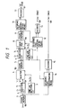
- Fig. 1 shows an embodiment of an encoding unit of the present invention.
- Original image data I1 is stored in a frame memory 1.
- the original image data read out from the frame memory 1 is reduced by a reduction circuit 2, and is output as a signal 101.
- the original image data read out from the frame memory 1 is input to a fine line detection circuit 3.
- the fine line detection circuit 3 detects a fine line, and outputs selection signals S1 and S2 in accordance with the detection result.
- the signals S1 and S2 are input to a selector 4.
- the selector 4 outputs "1", "0", or the signal 101 as a signal 103.
- the signal 103 is stored in a frame memory 5.
- the signal stored in the frame memory 5 corresponds to 1/2 original image data.
- the fine line detection circuit 3 is arranged in parallel with the reduction circuit 2, and reduced image data is formed based on the output from the fine line detection circuit 3. Thus, a fine line which would be lost if only the reduction circuit 2 is arranged can be preserved.
- the 1/2 image data read out from the frame memory 5 is reduced to a 1/4 original image by a reduction circuit 6, a fine line detection circuit 7, and a selector 8, and is stored in a frame memory 9 as 1/4 image data.
- Reference pixel determination means (or circuits) 10, 12, and 14 respectively detect sizes (the numbers of pixels) of image data stored in the frame memories 9, 5, and 1, and set the optimal numbers of pixels and optimal reference pixel positions in encoding.
- An encoder 11 encodes the 1/4 image data stored in the frame memory 9 using the reference pixel set by the reference pixel determination means 10, and outputs the encoded data as a first-stage signal 107.
- encoders 13 and 15 encode the 1/2 image data and original image data stored in the frame memories 5 and 1 using the reference pixels set by the reference pixel determination means 12 and 14, and output encoded data as second- and third-stage signals 108 and 109, respectively.
- the first- to third-stage image data are encoded and transmitted in turn in the order starting from image data having a lower resolution, so that a receiver side can quickly identify the entire image. If the receiver side does not need the data, it can stop the following transmission. Thus, an efficient image communication service can be provided.
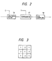
- Fig. 2 is a block diagram of the reduction circuits 2 and 6.
- Each reduction circuit comprises a low-pass filter 16, a comparator 17, and a sub-sampling circuit 18.
- a parameter C for adjusting a degree of smoothness is input to the low-pass filter 16.
- a threshold value T is input to the comparator 17. These values are determined based on required image quality and encoding efficiency.
- a signal output from the low-pass filter 16 is binarized by the comparator 17 based on the threshold value T. The binarized signal is thinned by the sub-sampling circuit 18 to 1/2 in the vertical and horizontal directions.
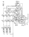
- Fig. 3 shows filter coefficients of the low-pass filter 16 having a 3 x 3 pixel size.
- a weighting coefficient of the central pixel is represented by C, a weighting coefficient of 1 is assigned to four pixels closest to the central pixel, and a weighting coefficient of 1 is assigned to the next closest pixels.
- the density W and the threshold value T have the following correspondences:
- Fig. 4 is a block diagram of the low-pass filter 16.
- An input signal is held in latches 20a, 20b, and 20c to be delayed by one pixel clock.
- An input signal delayed by one line is held in each of line memories 19-a and 19-b.
- signals whose pixel positions correspond to the latches 20a, 20b, and 20c can be obtained from latches 20d, 20e, and 20f or latches 20g, 20h, and 20i.
- the output signals from the latches 20a, 20c, 20g, and 20i are added by an adder 21a to calculate a total sum.
- the total sum output from the adder 21a is multiplied with a constant (x1) by a multiplier 22a.
- the output signals from the latches 20b, 20d, 20f, and 20h are added by an adder 21b to calculate a total sum.
- the total sum from the adder 21b is multiplied with a constant (x2) by a multiplier 22b.
- the output signal from the latch 20e i.e, data of the central pixel
- xC constant
- the C value can be externally set.
- the output signals from the multipliers 22a, 22b, and 22c are added by an adder 23 to calculate a total sum W.
- the total sum W is then output.
- the output signal from the adder 23 is compared with the threshold value T by the comparator 17 (Fig. 2). When the total sum W is larger than the threshold value T, a signal "1" is obtained; otherwise, a signal "0" is obtained.
- the threshold value T can also be externally set.
- Fig. 5 is a view for explaining an operation of the sub-sampling circuit 18.
- Hatched pixel data (Fig. 5) are sampled at every other timings respectively in the main scan and sub scan directions, thereby forming a sub-sampling image of a 1/2 size (1/4 in terms of an area). This operation can be easily realized by adjusting latch timings of image data.
- the fine line detection circuits 3 and 7 will be described below.
- a fine line or the like of a one-pixel width may be lost.
- Figs. 7A and 8A show examples of such images.
- the low-pass filter output (Fig. 3) becomes 4, and this black line disappears unless the threshold value T of the comparator (Fig. 2) is set to be 4 or less.
- a white line (black background) shown in Fig. 8A disappears unless the threshold value T is set to be (C+8) or more.
- an edge of an image can be detected by a linear differential filter.
- a linear differential filter For example, in the case of the image shown in Fig. 7A, an edge changing from black to white can be detected by a linear differential filter of 3 x 3 pixels shown in Fig. 7B. More specifically, only when an edge changing from black to white is present, a power of a filtering result is increased.
- the filtering result in Fig. 7A is 3.
- an edge changing from white to black can be detected by a linear differential filter shown in Fig. 8B. In this case, a power of a filtering result is also 3.
- Fig. 6 is a block diagram of the fine line detection circuits 3 and 7.
- Fig. 6 an arithmetic operation for fine line detection using the linear differential filter is simplified.
- the circuit shown in Fig. 6 includes line memories 24a, 24b, and 24c for respectively holding input pixels of one line, latches 25a to 25k for temporarily storing reference pixels used in an arithmetic operation corresponding to linear differentiation, a latch 60 for adjusting a timing, AND gates 61a to 61l, inverters 62a to 62n, and OR gates 63a and 63b.
- An input signal is held in the latches 25i, 25j, and 25k to be delayed by one pixel clock.
- the line memories 24a, 24b, and 24c respectively hold input signals delayed by one line.
- Signals whose pixel positions correspond to the latches 25i, 25j, and 25k can be obtained from the latches 25f, 25g, and 25h, and the latches 25c, 25d, and 25e.
- pixel data (central pixel) held in the latch 25g corresponds to data held in the latch 20e shown in Fig. 4.
- 3 x 3 pixels stored in the latches 25k, 25j, 25i, 25h, 25g, 25f, 25e, 25d, and 25c respectively correspond to 3 x 3 pixel latches 20a, 20b, 20c, 20d, 20e, 20f, 20g, 20h, and 20i in Fig. 4.
- the latch 25a latches a pixel two lines before the pixel of interest through the line memory 24c and the latch 60.
- the latch 25b latches a pixel two pixels before the pixel of interest.
- a linear differential value can be calculated based on the 3 x 3 pixels latched in the latches 25c to 25k in Fig. 6.
- the following logical formula is taken into consideration. If data held in the latches 25a to 25k in Fig. 6 are represented by a to k , reversed data of the data a to k are represented by a ⁇ to k ⁇ , a logical sum is represented by "+”, and a logical product is represented by " ⁇ ”, the following logical formula can be considered in place of the linear differential filter shown in Fig. 7B.
- the black line having a one-pixel width shown in Fig. 7A corresponds to c , f , and i .
- V B (c ⁇ f ⁇ i) ⁇ ( e ⁇ ⁇ h ⁇ ⁇ k ⁇ )
- V B 1
- an edge changing from black to white can be detected.
- this detection is not preferable in reduction for reducing two pixels to one pixel.
- V′ B (c ⁇ f ⁇ i) ⁇ ( e ⁇ ⁇ h ⁇ ⁇ k ⁇ ) ⁇ b ⁇
- V' W 1.
- V' B and V' W are used for detecting vertical black and white lines each having a one-pixel width.
- the line memories and latches constituting the low-pass filter are different from those constituting the fine line detection circuits. Some of the line memories and latches of the fine line detection circuit can be commonly used as those for the low-pass filter.
- the encoders 11, 13, and 15 perform an encoding operation in accordance with arithmetic codes.
- a value of a pixel of interest is predicted from surrounding pixels.
- a symbol of the predicted pixel is given by a major symbol, symbols of other pixels are given by minor symbols, and a probability of generation of minor symbols is represented by P.
- encoding is performed.
- C(S) and C(S') + A(S'0) are compared.
- Fig. 9 is a block diagram of a circuit for predicting a pixel of interest (target pixel).
- a frame memory 26 stores image data to be encoded.
- a frame memory 27 stores image data obtained by 1/2 sub-sampling the image (image sent in the immediately preceding stage) stored in the frame memory 26.
- the memories 26 and 27 respectively comprise two-dimensional memories. If a clock of an x address is represented by ⁇ 1 and a clock of a y address is represented by ⁇ 2, the clocks ⁇ 1 and ⁇ 2 are supplied to the frame memory A, and clocks 1/2 ⁇ 1 and 1/2 ⁇ 2 each having a 1/2 frequency are supplied to the frame memory B. Thus, one pixel in the frame memory B corresponds to 2 x 2, i.e,. four pixels in the frame memory A.
- Data from the frame memories 26 and 27 become one-line delayed data in line memories 28 and 29, and these data are then input to latches 30a to 30c and 31a and 31b.
- Each latch latches data delayed by one pixel. If the outputs from these latches are caused to correspond to pixel positions shown in Fig. 10, a pixel of interest (*) corresponds to the output from the latch 30d; a pixel No. 1 in Fig. 10, the latch 30e; No. 2, the latch 30b; No. 3, 30a; and No. 4, the latch 30c.
- a pixel No. 5 corresponds to the output from the latch 31b; No. 6, the latch 31a; No. 7, the latch 31d; No. 8, the latch 31c; and No. 9, the latch 31e.
- the pixel No. 5 in Fig. 11 is one including a pixel of interest (target pixel).
- a 2-bit signal for identifying the position of the pixel of interest in the pixel No. 5 (four states of upper left, upper right, lower left, and lower right) is generated by a counter 32 based on the clocks ⁇ 1 and ⁇ 2.
- AND gates 33a to 33k calculate logical products between signals on lines 201 to 211 set by a controller (not shown) and outputs from the latches 30a to 30c, 30e, and 31a to 31e, and the counter, respectively, thereby outputting a prediction signal 300 of the pixel of interest. The operation of this portion will be described in detail below.
- a pixel of interest is predicted from states or values of surrounding pixels, and a skew value is updated while calculating a "hit" probability of prediction. Therefore, in order to reflect the statistic nature of a symbol string to be encoded in a skew value, a considerable number of symbols for grasping the statistic nature are required in each state. For example, if the total number of symbols is 65,536, when the number of states is 211, an average number of symbols assigned to each state is 32, and it is difficult to grasp the statistic nature of the symbol string in each state.
- a controller (not shown) controls the number of predicted states or values in accordance with the number of symbols to be encoded. More specifically, in hierarchical encoding, since an image is reduced in every stage, the number of symbols to be encoded is smallest in the first stage, and it is increased toward the higher stages like the second stage, the third stage,.... When the number of symbols is small, the signals on lines 203, 209, and 211 are set to be "1", and the signals on the remaining lines are set to be "0", so that 3 bits (8 states) can be used as the number of states or values. As the number of symbols is increased, the number of "1"s set in the signals 201 to 211 is increased, thus increasing the number of states.
- Fig. 18 shows an example of values of the signals on lines 201 to 211 in this embodiment. This is merely an example, and the way of setting the states or values and signals to be set are not limited to this.
- Fig. 12 is a block diagram of a circuit for dynamically changing the skew value Q and a minor symbol lps.
- a status signal G300 and a pixel of interest D301 are respectively input to a status counter 40 and a minor symbol counter 41.
- internal counters corresponding in number to the states are prepared to allow a count operation in units of states, and are selected by a status signal G.
- the status counter 40 counts the number of generation times of a certain state for each state. When the count value exceeds a setup value S302, the counter 40 outputs an updating signal 303.
- An LUT 42 prestores Q G 305 as the next encoding parameter, a signal 306 for reversing mps (major symbols) so far, and data called a zero count (CT) 307 for generation of lc minor symbols.
- CT zero count
- Fig. 19 shows an example of the content of the LUT 42.
- CT 0 is set, and new Q G and the next CT value are obtained based on the lc value.
- N[x] is a closest integer value.
- Equation (1) an exponential part when the generation probability of minor symbols generated when S states continue (CT+1) times is approximated by a power of 2 is given by Q G .
- a latch 43 latches the current skew value Q G 305, the mps reversal signal 306, and CT 307, and latches the output from the LUT 42 in response to the updating signal 303 to be updated to a new state.
- the LUT 42 receives the count signal lc of minor symbols, and the previous CT value 307, and outputs the skew value Q G , the mps reversal signal, and CT which are updated according to Fig. 19.
- An mps value latch 44 latches a major symbol used in encoding so far, and this state is updated by the mps reversal signal.
- An mps/ lps ⁇ signal as an output of the latch 44 is supplied to the minor symbol counter.
- Encoding is performed based on the determined skew value Q G and mps/ lps ⁇ .
- Fig. 13 is a block diagram of an arithmetic code encoder. If a skew value is assumed to be the skew value Q G 305 from the latch 43 shown in Fig. 12, the skew value Q G 305 and the mps/ lps ⁇ signal 308 are input, so that an arithmetic operation given by equation (1) of pixel of interest data D is performed by an encoder, thus obtaining encoding data 401.
- Fig. 14 is a block diagram of a decoder.
- the same prediction circuit (Fig. 9) and dynamic adaptive circuit as in the encoding unit are prepared in the decoding side.
- a decoder 46 performs a decoding arithmetic operation using a skew value Q D 321 of a decoder side, and a minor symbol LPS D 322 and receiving data 323 from an LUT, thus obtaining decoding data 402.
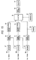
- Fig. 15 shows an embodiment of a decoding unit.
- the first-stage signal 107 is decoded by a decoder 47, and is stored in a frame memory 50. This signal is converted to high-resolution data by x4 interpolation processing of an interpolation device 53. The high-resolution data is stored in a video memory 56 after a selector 55 is switched by a controller 59.
- the video memory 56 comprises a 2-port memory. Therefore, an image obtained at a receiver side is always displayed on a monitor 57.
- the second-stage signal 108 is decoded by a decoder 48 with reference to the data stored in the frame memory 50, and is stored in a frame memory 51. This data is subjected to x2 interpolation processing by an interpolation device 54, and is stored in the video memory 56 upon switching of the selector 55.
- the third-stage signal 109 is similarly decoded, it is displayed on the monitor 57.
- a signal from a frame memory 52 as a decoded third-stage image signal is output to a printer 58 to obtain a hard copy.
- the first embodiment employs a system for adjusting a degree of smoothness in accordance with a weighting coefficient of the central value of a 3 x 3 coefficient matrix of the low-pass filter.
- T ⁇ 1 + 3 ⁇ 2 2 When W ⁇ T, 1; When W ⁇ T, 0.
- lc/S is obtained from the number of minor symbols lc among S pixels to determine a new skew value Q G from Fig. 20.
- Q G is determined using the updated Q G and lc/S.
- a value Q G ′ in updating is calculated by, e.g., the following equation, and is stored in a table: 1 2 QG' ⁇ 1 2 QG + lc S 2
- Fig. 17 shows an embodiment in this case, and a Q G signal 305 is input to an LUT 42 to determine Q G to be updated.
- the available number of states is controlled in each stage.
- the number of states can be controlled in accordance with an image size to be encoded. For example, when an image size of a third stage is 1024 x 1024 pixels, the number of states can be controlled to 27 states; when it is 3072 x 4096 pixels, it can be controlled to 211 states.
- the stages can be further segmented, and the reference pixel position and the number of reference pixels can be changed in units of image sizes.
- a reference pixel position suitable therefore is set to perform encoding.
- a filter for adjusting a smoothing effect for an image before it is subjected to resolution conversion is added, so that quality and encoding efficiency of an image at an initial stage to be transmitted can be arbitrarily selected.
Claims (10)
- Bildkodiervorrichtung mit Reduktionsmitteln (2, 6) zur Reduzierung des Auflösungsvermögens eines eingegebenen Bildes, und mit Kodiermitteln (15, 13, 11) zur Kodierung des eingegebenen Bildes und des reduzierten, von den Reduktionsmitteln erzeugten Bildes, wobei die Kodiermittel ein Zielpixel bezogen auf Bezugspixel kodieren, dadurch gekennzeichnet, daß die Kodiermittel (15, 13, 11) ein Zielpixel des eingegebenen Bildes bezüglich eines ersten Satzes von Bezugspixeln kodieren, verbunden mit dem Ziel, ein reduziertes Bild zu erzeugen und ein Ziepixel des reduzierten Bildes bezüglich eines zweiten Satzes von Bezugspixeln kodieren, die an das Zielpixel angegliedert sind, wobei die Bezugspixel bei der Kodierung eines Zielpixels in dem reduzierten Bild verwendet werden, das Positionen hinsichtlich des Zielpixels hat, welche sich von den Positionen des ersten Satzes der Bezugspixel hinsichtlich ihres angegliederten Zielpixels unterscheiden.
- Vorrichtung nach Anspruch 1, dessen Kodiermittel (15, 13, 11) das Zielpixel bezüglich der das Zielpixel umgebenden Pixel kodiert.
- Vorrichtung nach einem der Ansprüche 1 oder 2, deren Kodiermittel (15, 13, 11) den Wert des Zielpixels bezüglich der zugeordneten Bezugspixel vorhersagt.
- vorrichtung nach einem der vorstehenden Ansprüche, deren Reduktionsmittel (2, 6) das Bild glättet, das es empfängt, das geglättete Bild binär umsetzt und das binäre Bild zur Zusammenstellung eines Bildes reduzierten Auflösungsvermögens unterabtastet.
- Vorrichtung nach einem der Ansprüche 2 und 3, deren Kodiermittel (15, 13, 11) zur Vorhersage des Zielpixels mit Bezugspixel-Bestimmitteln (201 bis 211, 33a bis k) zur Bestimmung der Positionen der Bezugspixel gemäß den Werten der umgebenden Pixel verbunden ist.
- Bildkodierverfahren mit den Verfahrensschritten:Eingabe eines ersten Bildes;Zusammenstellen eines zweiten Bildes aus dem ersten Bild mit einem Auflösungsvermögen, das geringer als das des ersten Bildes ist; undKodieren des ersten und zweiten Bildes durch Kodierung von auf Bezugspixel bezogenen Zielpixeln, dadurch gekennzeichnet, daß bei der Kodierung des ersten Bildes das Zielpixel bezogen auf einen ersten Satz von Bezugspixeln kodiert wird und daß bei der Kodierung des zweiten Bildes das Zielpixel bezogen auf einen zweiten Satz von sich in ihrer Position von dem ersten Satz der Bezugspixel unterscheidenden Bezugspixeln kodiert wird.
- Verfahren nach Anspruch 6, bei dem der Verfahrensschritt des Kodierens des Zielpixels bezogen auf umgebende Pixel des Zielpixels erfolgt.
- Verfahren nach Anspruch 6 oder 7, bei dem in dem Verfahrensschritt des Kodierens ein auf die Bezugspixel bezogener Wert des Zielpixels vorhergesagt wird.
- Verfahren nach einem der Ansprüche 6 bis 8, bei dem in dem Verfahrensschritt der Reduktion des ersten Bildes dieses geglättet wird, das geglättete Bildsignal binär umgesetzt wird und das binäre Bild unterabgetastet wird, um das zweiten Bild aufzubauen.
- Verfahren nach einem der Ansprüche 6 bis 9, das des weiteren den Verfahrensschritt des Anweisens des Auflösungsvermögen eines zu kodierenden Bildes und der Bestimmung der Positionen von Bezugspixeln gemäß dem angewiesenen Auflösungsvermögen des zu kodierenden Bildes umfaßt.
Applications Claiming Priority (2)
| Application Number | Priority Date | Filing Date | Title |
|---|---|---|---|
| JP63332637A JPH02177766A (ja) | 1988-12-28 | 1988-12-28 | 2値画像の階層的符号化方式 |
| JP332637/88 | 1988-12-28 |
Publications (3)
| Publication Number | Publication Date |
|---|---|
| EP0376679A2 EP0376679A2 (de) | 1990-07-04 |
| EP0376679A3 EP0376679A3 (de) | 1992-01-22 |
| EP0376679B1 true EP0376679B1 (de) | 1996-05-01 |
Family
ID=18257182
Family Applications (1)
| Application Number | Title | Priority Date | Filing Date |
|---|---|---|---|
| EP89313590A Expired - Lifetime EP0376679B1 (de) | 1988-12-28 | 1989-12-27 | Bildkodiervorrichtung und Bildkodierverfahren |
Country Status (4)
| Country | Link |
|---|---|
| US (1) | US5371606A (de) |
| EP (1) | EP0376679B1 (de) |
| JP (1) | JPH02177766A (de) |
| DE (1) | DE68926386T2 (de) |
Families Citing this family (26)
| Publication number | Priority date | Publication date | Assignee | Title |
|---|---|---|---|---|
| EP0858210B1 (de) * | 1990-03-05 | 2003-12-17 | Canon Kabushiki Kaisha | Bildverarbeitungsgerät |
| US5255105A (en) * | 1990-03-17 | 1993-10-19 | International Computers Limited | Encoding image data |
| GB9006080D0 (en) * | 1990-03-17 | 1990-05-16 | Int Computers Ltd | Progressive encoding |
| JP2712863B2 (ja) * | 1991-03-12 | 1998-02-16 | 国際電信電話株式会社 | 疑似階調画像の階層的符号化方式 |
| EP0597698B1 (de) * | 1992-11-13 | 1998-08-05 | Canon Kabushiki Kaisha | Bildverarbeitungsgerät und Verfahren zur Bildverarbeitung |
| JP3428678B2 (ja) * | 1993-04-21 | 2003-07-22 | キヤノン株式会社 | 画像処理装置及び方法 |
| JPH07322252A (ja) | 1994-05-23 | 1995-12-08 | Canon Inc | 画像符号化装置 |
| JPH08125868A (ja) * | 1994-10-19 | 1996-05-17 | Canon Inc | 画像処理装置及び方法 |
| JP3427554B2 (ja) * | 1995-03-01 | 2003-07-22 | オムロン株式会社 | 画像処理装置及び方法 |
| JP4272711B2 (ja) | 1995-05-15 | 2009-06-03 | キヤノン株式会社 | 画像生成方法及び装置 |
| US6021259A (en) * | 1995-07-10 | 2000-02-01 | International Business Machines Corporation | Apparatus and method for conversion of structured data between different formats |
| US5844608A (en) * | 1996-12-12 | 1998-12-01 | Thomson Consumer Electronics, Inc. | Picture element processor for a memory management system |
| US6411395B1 (en) * | 1997-07-23 | 2002-06-25 | International Business Machines Corporation | Apparatus and method for conversion of data between different formats |
| US6512793B1 (en) | 1998-04-28 | 2003-01-28 | Canon Kabushiki Kaisha | Data processing apparatus and method |
| SG75189A1 (en) | 1998-12-04 | 2000-09-19 | Canon Kk | Image processing apparatus method therefor and recording medium storing image processing program |
| ATE509330T1 (de) * | 1999-12-04 | 2011-05-15 | Luratech Imaging Gmbh | Verfahren zur kompression von gescannten farb- und/oder graustufendokumenten |
| DE19958553A1 (de) | 1999-12-04 | 2001-06-07 | Luratech Ges Fuer Luft Und Rau | Verfahren zur Kompression von gescannten Farb- und/oder Graustufendokumenten |
| US6968088B2 (en) * | 2000-03-28 | 2005-11-22 | Canon Kabushiki Kaisha | Modification of detected quantization step size from the encoded bitstream based on a region of interest (ROI) bitmask |
| US6853930B2 (en) * | 2001-02-27 | 2005-02-08 | Hitachi, Ltd. | System for aiding the preparation of operation and maintenance plans for a power generation installation |
| JP2003304404A (ja) * | 2002-04-09 | 2003-10-24 | Canon Inc | 画像符号化装置 |
| JP4612797B2 (ja) * | 2004-03-11 | 2011-01-12 | キヤノン株式会社 | 符号化装置、符号化方法 |
| JP4702928B2 (ja) * | 2004-03-12 | 2011-06-15 | キヤノン株式会社 | 動画像符号化装置及び復号装置及びその制御方法、並びにコンピュータプログラム及びコンピュータ可読記憶媒体 |
| JP2005295505A (ja) * | 2004-03-12 | 2005-10-20 | Canon Inc | 動画像符号化装置及び動画像復号装置及びそれらの制御方法、並びに、コンピュータプログラム及びコンピュータ可読記憶媒体 |
| JP3915795B2 (ja) | 2004-03-29 | 2007-05-16 | コニカミノルタビジネステクノロジーズ株式会社 | 画像処理装置および画像処理プログラム |
| JP4771541B2 (ja) * | 2006-08-08 | 2011-09-14 | キヤノン株式会社 | 画像符号化装置及び方法、並びに、コンピュータプログラム及びコンピュータ可読記憶媒体 |
| JP5240194B2 (ja) * | 2007-06-07 | 2013-07-17 | ソニー株式会社 | 信号処理方法および信号処理装置 |
Citations (1)
| Publication number | Priority date | Publication date | Assignee | Title |
|---|---|---|---|---|
| EP0357386A2 (de) * | 1988-08-30 | 1990-03-07 | Canon Kabushiki Kaisha | Bildcodierungsgerät |
Family Cites Families (20)
| Publication number | Priority date | Publication date | Assignee | Title |
|---|---|---|---|---|
| US4222076A (en) * | 1978-09-15 | 1980-09-09 | Bell Telephone Laboratories, Incorporated | Progressive image transmission |
| US4261018A (en) * | 1979-06-18 | 1981-04-07 | Bell Telephone Laboratories, Incorporated | Progressive image transmission |
| JPS58153450A (ja) * | 1982-03-06 | 1983-09-12 | Nippon Telegr & Teleph Corp <Ntt> | フアクシミリ情報等の解像度変換方法 |
| JPS60148279A (ja) * | 1983-12-28 | 1985-08-05 | インタ−ナショナル ビジネス マシ−ンズ コ−ポレ−ション | 画像処理システム |
| JPS61147668A (ja) * | 1984-12-21 | 1986-07-05 | Nippon Telegr & Teleph Corp <Ntt> | 画像の縮小変換法 |
| JPS61263369A (ja) * | 1985-05-17 | 1986-11-21 | Hitachi Medical Corp | 多段階画像圧縮復元方法 |
| JP2525768B2 (ja) * | 1986-02-25 | 1996-08-21 | 日本電信電話株式会社 | 画像の縮小変換方法 |
| GB8630887D0 (en) * | 1986-12-24 | 1987-02-04 | Philips Electronic Associated | Encoding & displaying pictures |
| JP2794281B2 (ja) * | 1986-07-10 | 1998-09-03 | 株式会社日立製作所 | デイザ信号の符号復号処理装置 |
| JPS63146558A (ja) * | 1986-12-09 | 1988-06-18 | Hitachi Ltd | フアクシミリ通信方式 |
| JPS63164759A (ja) * | 1986-12-26 | 1988-07-08 | Matsushita Graphic Commun Syst Inc | 二値化処理方法 |
| JPS63164575A (ja) * | 1986-12-26 | 1988-07-07 | Radio Res Lab | 画像デ−タの符号化方式 |
| JPH07118754B2 (ja) * | 1987-04-15 | 1995-12-18 | キヤノン株式会社 | 画像通信装置 |
| JP2534276B2 (ja) * | 1987-10-09 | 1996-09-11 | インターナショナル・ビジネス・マシーンズ・コーポレーション | オリジナル・イメ−ジのペル信号の処理方法 |
| US4873577A (en) * | 1988-01-22 | 1989-10-10 | American Telephone And Telegraph Company | Edge decomposition for the transmission of high resolution facsimile images |
| CA1306052C (en) * | 1988-03-18 | 1992-08-04 | Yoshiyuki Okada | Process and apparatus for reducing picture with fine line disappearance prevention |
| EP0357388B1 (de) * | 1988-08-30 | 1997-10-22 | Canon Kabushiki Kaisha | Bildcodierungsverfahren |
| US5398123A (en) * | 1988-08-31 | 1995-03-14 | Canon Kabushiki Kaisha | Image processing method and apparatus capable of automatic color masking |
| US5086487A (en) * | 1988-11-24 | 1992-02-04 | Canon Kabushiki Kaisha | Method and apparatus for image encoding in which reference pixels for predictive encoding can be selected based on image size |
| EP0372950B1 (de) * | 1988-12-08 | 1995-07-05 | Canon Kabushiki Kaisha | Bildreduzierungsvorrichtung |
-
1988
- 1988-12-28 JP JP63332637A patent/JPH02177766A/ja active Pending
-
1989
- 1989-12-27 DE DE68926386T patent/DE68926386T2/de not_active Expired - Fee Related
- 1989-12-27 EP EP89313590A patent/EP0376679B1/de not_active Expired - Lifetime
-
1992
- 1992-11-02 US US07/970,250 patent/US5371606A/en not_active Expired - Lifetime
Patent Citations (1)
| Publication number | Priority date | Publication date | Assignee | Title |
|---|---|---|---|---|
| EP0357386A2 (de) * | 1988-08-30 | 1990-03-07 | Canon Kabushiki Kaisha | Bildcodierungsgerät |
Also Published As
| Publication number | Publication date |
|---|---|
| US5371606A (en) | 1994-12-06 |
| EP0376679A2 (de) | 1990-07-04 |
| EP0376679A3 (de) | 1992-01-22 |
| DE68926386T2 (de) | 1996-09-05 |
| DE68926386D1 (de) | 1996-06-05 |
| JPH02177766A (ja) | 1990-07-10 |
Similar Documents
| Publication | Publication Date | Title |
|---|---|---|
| EP0376679B1 (de) | Bildkodiervorrichtung und Bildkodierverfahren | |
| EP0392701B1 (de) | Bildverkleinerungsgerät | |
| US5086487A (en) | Method and apparatus for image encoding in which reference pixels for predictive encoding can be selected based on image size | |
| EP0357386B1 (de) | Bildcodierungsgerät | |
| EP0738070B1 (de) | Bildverarbeitungsverfahren und -vorrichtung | |
| EP0504903B1 (de) | Anordnung und Verfahren zur Vorverarbeitung binärer Bilddaten von Lauflängekodierung | |
| US5331426A (en) | Image encoding method | |
| EP0613290B1 (de) | Verfahren und Gerät zur Kompression binärer Bilddaten | |
| US5655032A (en) | Coding method and apparatus therefor | |
| EP0357388B1 (de) | Bildcodierungsverfahren | |
| JPH0265372A (ja) | 画像の符号化方法及び装置 | |
| JPH029268A (ja) | 画像処理装置 | |
| JP2941843B2 (ja) | 画像信号の縮小装置及び方法 | |
| JPS5812472A (ja) | 画信号処理装置 | |
| JP2976386B2 (ja) | 2値画像変倍装置 | |
| JPS62234466A (ja) | 画像処理装置 | |
| JPS61253584A (ja) | 画像処理装置 | |
| JPH0316382A (ja) | 画像符号化装置 | |
| JPH09261468A (ja) | 画像処理装置 | |
| JPH11220627A (ja) | 疑似中間調画像の符号化装置及び符号化方法 | |
| JPH04189069A (ja) | 画像処理装置 | |
| JPH0265373A (ja) | 画像の符号化方法 |
Legal Events
| Date | Code | Title | Description |
|---|---|---|---|
| PUAI | Public reference made under article 153(3) epc to a published international application that has entered the european phase |
Free format text: ORIGINAL CODE: 0009012 |
|
| AK | Designated contracting states |
Kind code of ref document: A2 Designated state(s): DE FR GB |
|
| 17P | Request for examination filed |
Effective date: 19901231 |
|
| PUAL | Search report despatched |
Free format text: ORIGINAL CODE: 0009013 |
|
| AK | Designated contracting states |
Kind code of ref document: A3 Designated state(s): DE FR GB |
|
| 17Q | First examination report despatched |
Effective date: 19931012 |
|
| GRAH | Despatch of communication of intention to grant a patent |
Free format text: ORIGINAL CODE: EPIDOS IGRA |
|
| GRAA | (expected) grant |
Free format text: ORIGINAL CODE: 0009210 |
|
| AK | Designated contracting states |
Kind code of ref document: B1 Designated state(s): DE FR GB |
|
| REF | Corresponds to: |
Ref document number: 68926386 Country of ref document: DE Date of ref document: 19960605 |
|
| ET | Fr: translation filed | ||
| PLBE | No opposition filed within time limit |
Free format text: ORIGINAL CODE: 0009261 |
|
| STAA | Information on the status of an ep patent application or granted ep patent |
Free format text: STATUS: NO OPPOSITION FILED WITHIN TIME LIMIT |
|
| 26N | No opposition filed | ||
| REG | Reference to a national code |
Ref country code: GB Ref legal event code: IF02 |
|
| PGFP | Annual fee paid to national office [announced via postgrant information from national office to epo] |
Ref country code: GB Payment date: 20051213 Year of fee payment: 17 |
|
| PGFP | Annual fee paid to national office [announced via postgrant information from national office to epo] |
Ref country code: FR Payment date: 20051216 Year of fee payment: 17 |
|
| PGFP | Annual fee paid to national office [announced via postgrant information from national office to epo] |
Ref country code: DE Payment date: 20060224 Year of fee payment: 17 |
|
| PG25 | Lapsed in a contracting state [announced via postgrant information from national office to epo] |
Ref country code: DE Free format text: LAPSE BECAUSE OF NON-PAYMENT OF DUE FEES Effective date: 20070703 |
|
| GBPC | Gb: european patent ceased through non-payment of renewal fee |
Effective date: 20061227 |
|
| REG | Reference to a national code |
Ref country code: FR Ref legal event code: ST Effective date: 20070831 |
|
| PG25 | Lapsed in a contracting state [announced via postgrant information from national office to epo] |
Ref country code: GB Free format text: LAPSE BECAUSE OF NON-PAYMENT OF DUE FEES Effective date: 20061227 |
|
| PG25 | Lapsed in a contracting state [announced via postgrant information from national office to epo] |
Ref country code: FR Free format text: LAPSE BECAUSE OF NON-PAYMENT OF DUE FEES Effective date: 20070102 |