EP0375266A2 - Appareil pour l'enregistrement et/ou la reproduction de disques optiques - Google Patents
Appareil pour l'enregistrement et/ou la reproduction de disques optiques Download PDFInfo
- Publication number
- EP0375266A2 EP0375266A2 EP89313052A EP89313052A EP0375266A2 EP 0375266 A2 EP0375266 A2 EP 0375266A2 EP 89313052 A EP89313052 A EP 89313052A EP 89313052 A EP89313052 A EP 89313052A EP 0375266 A2 EP0375266 A2 EP 0375266A2
- Authority
- EP
- European Patent Office
- Prior art keywords
- optical disc
- recording
- optical
- signal
- detecting
- Prior art date
- Legal status (The legal status is an assumption and is not a legal conclusion. Google has not performed a legal analysis and makes no representation as to the accuracy of the status listed.)
- Granted
Links
Images


Classifications
-
- G—PHYSICS
- G11—INFORMATION STORAGE
- G11B—INFORMATION STORAGE BASED ON RELATIVE MOVEMENT BETWEEN RECORD CARRIER AND TRANSDUCER
- G11B7/00—Recording or reproducing by optical means, e.g. recording using a thermal beam of optical radiation by modifying optical properties or the physical structure, reproducing using an optical beam at lower power by sensing optical properties; Record carriers therefor
- G11B7/08—Disposition or mounting of heads or light sources relatively to record carriers
- G11B7/085—Disposition or mounting of heads or light sources relatively to record carriers with provision for moving the light beam into, or out of, its operative position or across tracks, otherwise than during the transducing operation, e.g. for adjustment or preliminary positioning or track change or selection
- G11B7/08505—Methods for track change, selection or preliminary positioning by moving the head
-
- G—PHYSICS
- G11—INFORMATION STORAGE
- G11B—INFORMATION STORAGE BASED ON RELATIVE MOVEMENT BETWEEN RECORD CARRIER AND TRANSDUCER
- G11B7/00—Recording or reproducing by optical means, e.g. recording using a thermal beam of optical radiation by modifying optical properties or the physical structure, reproducing using an optical beam at lower power by sensing optical properties; Record carriers therefor
- G11B7/08—Disposition or mounting of heads or light sources relatively to record carriers
- G11B7/09—Disposition or mounting of heads or light sources relatively to record carriers with provision for moving the light beam or focus plane for the purpose of maintaining alignment of the light beam relative to the record carrier during transducing operation, e.g. to compensate for surface irregularities of the latter or for track following
Definitions
- the present invention relates to a recording and/or reproduction apparatus for an optical disc, specifically for an optical disc on which recording tracks are preformatted with sample pits or pregrooves.
- Writable optical discs having a layer of a light sensitive medium, whose reflective index changes in response to the light, formed on the surface of the disc, exist on which recording tracks are formed by sample pits or spiral pregrooves.
- Figures 1A, 1B and 1C of the accompanying drawings show a plan view of such a writable optical disc and enlarged diagrams of recording tracks.
- data areas D ⁇ A are formed by n sectors H1, to H n as shown in figure 1A.
- the tracks are radially separated by pregrooves G.
- the head portions of the tracks are used as an area ADD ⁇ A of address data (51 bytes) which is preformatted during manufacture by, for instance, an embossing process or the like.
- a total reflective area in which nothing is recorded is formed immediately following the address data area ADD ⁇ A.
- a data area D ⁇ A into/from which data can be actually written or read out is positioned.
- a laser spot S irradiated from the optical head is subjected to position control via the tracking servo by the latter detecting the reflected light from the wobbling pits P1, and P2 or the pregroove G.
- the laser spot S is controlled so as to always pass down the centre of the track.
- the mirror area (M ⁇ A) is provided to detect the power of the laser spot and the focusing state. By detecting the reflected light of the laser beam irradiating the mirror area, optimum focusing servo can be applied and, in the reading, writing or erasing mode, the intensity of the laser power can be controlled.
- An optical head for a laser beam of such an optical disc is generally constructed by a biaxial actuator (fine actuator) to apply focusing servo control and tracking servo control and a linear motor (coarse actuator) to move the fine actuator in the radial direction of the disc.
- a biaxial actuator fine actuator
- a linear motor coarse actuator
- a two-part detector having two divided photo-sensitive surface area is used. By detecting a field image from the optical disc surface which is formed on the two divided areas of the detector, using a push-pull method a tracking error signal can be detected.
- a jump signal is supplied to the coarse actuator.
- the optical head is moved at a high speed to seek in the direction toward the inner track or toward the outer track on the optical disc, the laser beam is irradiated onto a target track, and data is read out or written at that point.
- FIG. 2 shows an outline of a conventional driving circuit to execute such a seeking operation.
- Reference numeral 1 denotes a drive amplifier for a fine actuator 2
- 3 indicates a drive amplifier for a coarse actuator 4.
- a tracking error signal TE is supplied from a terminal a of a switch S1, through the drive amplifier 1 to a tracking coil of the fine actuator 2.
- the integrated voltage of the tracking error signal TE is also supplied to the coarse actuator 4 through a terminal a of the switch S2.
- the switch S2 In the seeking operation to move the optical head to a target track, the switch S2 is switched and a seeking voltage S v is supplied from a terminal b of the switch S2 to move the coarse actuator 4 to the target track at a high speed.
- the seeking voltage S v comprises an accelerating voltage and a decelerating voltage in order to make the seeking speed high and has a drive waveform such that the optical head stops over the target track.
- an objective lens of the fine actuator 2 is supported so that it can oscillate, if the coarse actuator 4 is moved at a high speed, the objective lens can be driven into severe oscillation at the resonant frequency of the fine actuator 2. As a result, it is difficult immediately to start the tracking servo over the target track or at a position near it.
- FIG. 2 there is proposed a method using a position sensor 5 (figure 2).
- the position sensor 5 detects the position in the radial direction of an objective lens L by irradiating a light P1, from the light source LS to an actuator A to drive the objective lens L and detecting the reflected lights P2 and P3 by detectors D1, and D2.
- a position signal representing the position of the objective lens L is fed back from the terminal b through a coefficient circuit 6, and the vibration of the objective lens L is suppressed.
- a recording and/or reproduction apparatus for an optical disc having recording tracks in which respective mirror areas are formed, comprising: an optical head for recording or reproducing information signal onto or from the optical disc, said heat having an optical detector for detecting a tracking error signal by a push-pull method; a fine actuator for precisely actuating said optical head finely; detecting means for detecting an output signal of said optical detector responding to reflected light from said mirror area; and driving means for driving said fine actuator in response to an output signal of said detecting means during a seeking operation.
- FIG 4 shows a block diagram of an embodiment of the present invention.
- reference numeral 10 denotes a coarse actuator constructing an optical head and 11 indicates a fine actuator mounted on the coarse actuator 10.
- the coarse actuator 10 includes a laser emitting source 10A, a lens 10B, a beam splitter 10C, and a drive coil 10D of a linear motor. Further, a two-divided detector 10E to detect the reflected light is provided.
- the fine actuator 11 has an objective lens 11A. The objective lens 11A is moved in the vertical and horizontal directions by a tracking coil 11B and a focusing coil 11C.
- Outputs of the two-divided detector 11E having two photo-sensitive surfaces A and B are supplied to an RF signal processing block 12.
- Data on the optical disc D is read out by the RF signal processing block 12 as the disc D rotates and a focusing error signal and a tracking error signal are produced.
- the tracking error signal can be obtained by subtracting a reproduced signal of a photosensitive surface B from a reproduced signal of a photosensitive surface A.
- the tracking error signal can be derived by sampling the reproduced signals corresponding to the wobbling pits P1, and P2 respectively and subtracting their sampled values.
- Reference numeral 13 denotes a data processing block. Address data of the optical disc D is detected and the data is read out. The position of the track which the optical head faces at present is detected by the address data.
- the tracking error signal TE is supplied to a tracking drive amplifier 19A through a phase compensating circuit 14, a differentiating circuit 15 and a terminal a of the switch SW1, thereby applying the tracking servo.
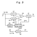
- FIG. 5 An example of the RF signal processing circuit 12 is shown in figure 5.
- One detecting signal SA and another detecting signal SB from the two-divided detector IOE are added together.
- the signal (SA + SB) is supplied to sampling circuits 22 and 23, and a clock generator 24 respectively.
- the clock generator 24 generates a clock signal synchronised with a reproduced signal.
- the clock signal is supplied to a sampling pulse generator 25.
- the sampling pulse generator 25 generates sampling pulses SP1, SP2, SP3 and SP4.
- the sampling pulse SP1 is supplied to the sampling circuit 22 and the sampling pulse SP2 is supplied to the sampling circuit 23.
- the timing of the sampling pulses SP1 and SP2 are in synchronism with that of the wobbling pits P1 and P2.
- An output signal of the sampling circuit 22 is subtracted from an output signal of the sampling circuit 23 by a subtracting circuit 26.
- An output signal from the subtracting circuit 26 is supplied to a sampling circuit 27.
- the sampling pulse SP3 for the sampling circuit 27 has a slight delay amount to the sampling pulse SP2.
- the tracking error signal TE is obtained from the sampling circuit 27.
- a differential signal (SA - SB) which is derived from subtracting two signals of the two divided detector 10E is supplied to a sampling circuit 28 from an input terminal 29.
- the sampling pulse SP4 for the sampling circuit 28 is generated when the laser beam is scanning the mirror area M ⁇ A.
- a push-pull or error signal LE is obtained from the sampling circuit 28.
- the push-pull signal LE is supplied to a spot position detecting section 16 as shown in figure 4.
- the spot position detecting section 16 comprises first and second low-pass filters 16A and 16B and a subtracting circuit 16C An output of the spot position detecting section 16 is supplied to the terminal b of the switch SW2 through an inverting coefficient circuit 17 and is also supplied to the terminal a of the switch SW2 through a phase compensator 18. An output of the switch SW2 is supplied to the drive coil 10D of the linear motor via a drive amplifier 19B of the coarse actuator 10. In the ordinary recording or reproducing mode, the tracking control of the fine actuator 11 is executed by the tracking error signal TE which is supplied from the terminal a of the switch SW1.
- the level of the push-pull or error signal LE indicates the deviation of the objective lens 11A, that is, the deviation of the fine actuator 11.
- the detection information from the spot position detecting section 16 is supplied from the terminal a of the switch SW2 to the drive coil 10D of the linear motor to drive the coarse actuator 10.
- the reflected light is detected by the two-divided detector IOE at the time when the laser beam irradiates the mirror area.
- the deviation of the objective lens relative to the coarse actuator 10 can be detected from the push-pull signal LE. Accordingly, be feeding back the deviation amount to the drive coil 10D of the coarse actuator 10, the tracking control of the coarse actuator 10 can be also executed.
- a skew component of the optical disc is detected from the first low-pass filter 16A having a time constant longer than the rotational period of the optical disc and the deviation of the objective lens 11A is detected by the second low-pass filter 16B which has a relatively short time constant. Therefore, the tracking signal of the coarse actuator 10, from which any influence by the skew is eliminated, is obtained from the subtracting circuit 16C.
- the switch SW2 is switched to the terminal b, and the seeking voltage S, is supplied to the drive amplifier 19B through the switch SW2.
- the linear motor is accelerated and is moved to a target track at a high speed.
- the coarse actuator 10 is controlled in a manner such that the velocity of the actuator increases simultaneously with the start of the seeking operation, the motor is decelerated from the middle point, and its velocity is set to almost zero at a position over the target track.
- the address data or sample pits are radially formed in the radial direction of the optical disc, when the moving velocity of the optical head is not so fast, an address area or a servo area can be detected.
- a control signal S2 is supplied to the switch SW1 from the data processing block 13 and then the terminal b of the switch SW1 is selected.
- the vibration component of the objective lens 11A due to the movement is detected by the low-pass filter 16B having a relatively short time constant i.
- the skew component of the disc is detected by the low-pass filter 16A which has a relatively long time constant ⁇ 2.
- the skew component is held by a signal S1.
- the signal of the vibration component which is output from the subtracting circuit 16C is supplied to the tracking coil 11B of the fine actuator 11 through the inverting coefficient circuit 17. Therefore, even when the objective lens 11A oscillates wildly when the optical head is moved at a high speed, at positions near the time points corresponding to the start and the finish the seeking operation, the vibration signal component is fed back to the tracking coil 11B of the fine actuator 11 and the vibration of the objective lens 11A can be suppressed.
- the terminal c of the switch SW1 is selected by a control signal S2 which is output from the data processing block 13 and the drive signal of the objective lens 11A supplied to the drive amplifier 19A is set to zero.
- the recording and/or reproduction apparatus of an optical disc of the present invention when address data can be read, the push-pull signal is always obtained by the two-divided detector, and the deviation information of the objective lens is detected. Therefore, the present invention achieves the advantage that even during the seeking operation, near the time point when the moving velocity decreases at a position near the target track, the vibration of the objective lens can be suppressed. As a result, the tracking servo can be applied soon after completion of the seeking operation.
Applications Claiming Priority (2)
| Application Number | Priority Date | Filing Date | Title |
|---|---|---|---|
| JP318524/88 | 1988-12-19 | ||
| JP63318524A JP2785290B2 (ja) | 1988-12-19 | 1988-12-19 | 光ディスクのシーク及びトラッキング装置 |
Publications (3)
| Publication Number | Publication Date |
|---|---|
| EP0375266A2 true EP0375266A2 (fr) | 1990-06-27 |
| EP0375266A3 EP0375266A3 (en) | 1990-11-28 |
| EP0375266B1 EP0375266B1 (fr) | 1994-10-05 |
Family
ID=18100075
Family Applications (1)
| Application Number | Title | Priority Date | Filing Date |
|---|---|---|---|
| EP89313052A Expired - Lifetime EP0375266B1 (fr) | 1988-12-19 | 1989-12-13 | Appareil pour l'enregistrement et/ou la reproduction de disques optiques |
Country Status (6)
| Country | Link |
|---|---|
| US (1) | US5157642A (fr) |
| EP (1) | EP0375266B1 (fr) |
| JP (1) | JP2785290B2 (fr) |
| KR (1) | KR0175653B1 (fr) |
| CA (1) | CA2005341C (fr) |
| DE (1) | DE68918679T2 (fr) |
Families Citing this family (11)
| Publication number | Priority date | Publication date | Assignee | Title |
|---|---|---|---|---|
| JPH0460929A (ja) * | 1990-06-25 | 1992-02-26 | Canon Inc | 光学ヘッド及び該光学ヘッドを備えた光学的情報記録再生装置 |
| US5450386A (en) * | 1991-04-05 | 1995-09-12 | Canon Kabushiki Kaisha | Optical disk device including a support member for movably supporting an objective lens in focusing and radial directions with respect to an optical disk |
| KR0167891B1 (ko) * | 1992-04-06 | 1999-03-20 | 강진구 | 디스크 시스템의 조기 브레이크 구동방법 |
| US5511052A (en) * | 1992-05-11 | 1996-04-23 | Eastman Kodak Company | Digital compensator for controlling a servo to correct the value of a given parameter of a system |
| JPH0963070A (ja) * | 1995-06-13 | 1997-03-07 | Matsushita Electric Ind Co Ltd | トラックアクセス方法および装置 |
| US5673240A (en) * | 1996-03-18 | 1997-09-30 | Nec Corporation | Seek control circuit for suppressing vibration of objective lens in optical head during seek operation |
| KR100346701B1 (ko) * | 1999-05-25 | 2002-08-01 | 삼성전자 주식회사 | 레이저 다이오드의 출력 제어 방법 및 이에 적합한 장치 |
| JP3507395B2 (ja) * | 2000-03-03 | 2004-03-15 | 株式会社日立製作所 | 回転電機及びそれを用いた電動車両 |
| CN100517474C (zh) * | 2002-12-30 | 2009-07-22 | 皇家飞利浦电子股份有限公司 | 光盘播放设备 |
| JP2005122810A (ja) * | 2003-10-16 | 2005-05-12 | Hitachi Ltd | 光ディスク装置 |
| CN116293113A (zh) * | 2015-12-10 | 2023-06-23 | 美国圣戈班性能塑料公司 | 流体输送耦合件 |
Citations (5)
| Publication number | Priority date | Publication date | Assignee | Title |
|---|---|---|---|---|
| EP0099576A2 (fr) * | 1982-07-21 | 1984-02-01 | Hitachi, Ltd. | Dispositif optique de traitement d'informations |
| EP0215556A2 (fr) * | 1985-07-30 | 1987-03-25 | Koninklijke Philips Electronics N.V. | Support d'enregistrement et circuit générateur de signaux d'alignement |
| EP0259913A2 (fr) * | 1986-08-29 | 1988-03-16 | Koninklijke Philips Electronics N.V. | Signal d'entraînement pour asservissement grossier par l'emploi d'un signal de compensation échantillonné |
| US4736353A (en) * | 1985-03-20 | 1988-04-05 | Hitachi Ltd. | Disc accessing using coarse and fine actuators with the fine actuator locked during coarse actuator movement |
| EP0272873A2 (fr) * | 1986-12-15 | 1988-06-29 | Sony Corporation | Systèmes asservis de suivi de piste pour lecteurs de disques optiques |
Family Cites Families (10)
| Publication number | Priority date | Publication date | Assignee | Title |
|---|---|---|---|---|
| KR880000999B1 (ko) * | 1981-11-25 | 1988-06-10 | 미쓰다 가쓰시게 | 광학적 정보 기억장치 |
| US4627039A (en) * | 1983-12-23 | 1986-12-02 | Magnetic Peripherals Inc. | Head positioning servo system for optical recording with coarse and fine control |
| JPS60143442A (ja) * | 1983-12-28 | 1985-07-29 | Olympus Optical Co Ltd | トラツキング方式 |
| JPS61104337A (ja) * | 1984-10-24 | 1986-05-22 | Hitachi Ltd | 光学的情報記録再生装置 |
| KR940002001B1 (ko) * | 1985-03-22 | 1994-03-12 | 가부시끼가이샤 히다찌세이사꾸쇼 | 액세스 방법과 그 정보 검색장치 |
| DE3618137A1 (de) * | 1985-05-31 | 1986-12-11 | Hitachi, Ltd., Tokio/Tokyo | Bildplatten-zugriffsverfahren und bildplattenspeicher |
| DE3618720A1 (de) * | 1985-06-05 | 1986-12-11 | Hitachi, Ltd., Tokio/Tokyo | Verfahren und vorrichtung zur spurnachfuehrung bei bildplatten |
| US4779253A (en) * | 1985-07-30 | 1988-10-18 | Laser Magnetic Storage International Company | Sampled servo for an optical disk drive |
| US4819219A (en) * | 1986-03-25 | 1989-04-04 | Kabushiki Kaisha Toshiba | Track jump control system for optical disk apparatus |
| JPS63825A (ja) * | 1986-06-19 | 1988-01-05 | Sharp Corp | 光情報記録再生装置 |
-
1988
- 1988-12-19 JP JP63318524A patent/JP2785290B2/ja not_active Expired - Lifetime
-
1989
- 1989-12-13 DE DE68918679T patent/DE68918679T2/de not_active Expired - Lifetime
- 1989-12-13 EP EP89313052A patent/EP0375266B1/fr not_active Expired - Lifetime
- 1989-12-13 CA CA002005341A patent/CA2005341C/fr not_active Expired - Lifetime
- 1989-12-15 US US07/451,197 patent/US5157642A/en not_active Expired - Lifetime
- 1989-12-15 KR KR1019890018632A patent/KR0175653B1/ko not_active IP Right Cessation
Patent Citations (5)
| Publication number | Priority date | Publication date | Assignee | Title |
|---|---|---|---|---|
| EP0099576A2 (fr) * | 1982-07-21 | 1984-02-01 | Hitachi, Ltd. | Dispositif optique de traitement d'informations |
| US4736353A (en) * | 1985-03-20 | 1988-04-05 | Hitachi Ltd. | Disc accessing using coarse and fine actuators with the fine actuator locked during coarse actuator movement |
| EP0215556A2 (fr) * | 1985-07-30 | 1987-03-25 | Koninklijke Philips Electronics N.V. | Support d'enregistrement et circuit générateur de signaux d'alignement |
| EP0259913A2 (fr) * | 1986-08-29 | 1988-03-16 | Koninklijke Philips Electronics N.V. | Signal d'entraînement pour asservissement grossier par l'emploi d'un signal de compensation échantillonné |
| EP0272873A2 (fr) * | 1986-12-15 | 1988-06-29 | Sony Corporation | Systèmes asservis de suivi de piste pour lecteurs de disques optiques |
Also Published As
| Publication number | Publication date |
|---|---|
| JPH02165427A (ja) | 1990-06-26 |
| EP0375266A3 (en) | 1990-11-28 |
| CA2005341C (fr) | 2000-02-08 |
| JP2785290B2 (ja) | 1998-08-13 |
| KR0175653B1 (ko) | 1999-04-15 |
| KR900010692A (ko) | 1990-07-09 |
| CA2005341A1 (fr) | 1990-06-19 |
| EP0375266B1 (fr) | 1994-10-05 |
| US5157642A (en) | 1992-10-20 |
| DE68918679D1 (de) | 1994-11-10 |
| DE68918679T2 (de) | 1995-02-09 |
Similar Documents
| Publication | Publication Date | Title |
|---|---|---|
| EP0191467B1 (fr) | Appareil à disque optique | |
| JPS626445A (ja) | 光ピツクアツプのトラツキング制御方式 | |
| EP0375266B1 (fr) | Appareil pour l'enregistrement et/ou la reproduction de disques optiques | |
| US5361245A (en) | Optical signal processing apparatus for detecting the direction of movement of an optical reading device relative to an optical disk | |
| JP3455298B2 (ja) | 光ビームの移動検出方法および光ディスク再生装置 | |
| US4918680A (en) | Focus-servo correction utilizing storage of detected focus errors | |
| US5621709A (en) | Tracking servo apparatus | |
| US5185730A (en) | Method for reading data from optical disk | |
| JPS6313264B2 (fr) | ||
| JP2947095B2 (ja) | 光ディスク装置及びアクセス制御方法 | |
| US4989194A (en) | Optical information processing method of driving auto-focusing and/or auto-tracking means in accordance with a stored servo signal when irradiation of a record medium with light beam is stopped, and apparatus therefor | |
| US6141305A (en) | Optical disk recording and reproducing apparatus and method and tracking servo apparatus and method | |
| KR100477501B1 (ko) | 디스크드라이브장치 | |
| US5124964A (en) | Focus servo gain setting circuit for optical record disc reproducing apparatus | |
| JPH0736233B2 (ja) | 光学的情報記録再生装置 | |
| US5805542A (en) | Optical disk apparatus with a groove/pit area discrimination circuit | |
| US5103440A (en) | Track access error correction apparatus for moving an optical head from one track location to another track location on an optical disc | |
| KR100209159B1 (ko) | 광디스크 시스템의 트랙 억세스 제어 장치 | |
| JPH077528B2 (ja) | 光学式情報記録装置 | |
| JP2785815B2 (ja) | 光ディスク装置 | |
| US4863228A (en) | Apparatus and a method of deflecting laser convergent light | |
| JPH02263333A (ja) | 光ヘッド装置 | |
| KR100606671B1 (ko) | 광 기록재생기의 액츄에이터 진동 방지 방법 | |
| JP2867361B2 (ja) | 光ディスク装置用ピックアップ | |
| JPS6344327A (ja) | 光学的情報記録再生装置のトラツキング装置 |
Legal Events
| Date | Code | Title | Description |
|---|---|---|---|
| PUAI | Public reference made under article 153(3) epc to a published international application that has entered the european phase |
Free format text: ORIGINAL CODE: 0009012 |
|
| AK | Designated contracting states |
Kind code of ref document: A2 Designated state(s): DE FR GB |
|
| PUAL | Search report despatched |
Free format text: ORIGINAL CODE: 0009013 |
|
| AK | Designated contracting states |
Kind code of ref document: A3 Designated state(s): DE FR GB |
|
| 17P | Request for examination filed |
Effective date: 19901221 |
|
| 17Q | First examination report despatched |
Effective date: 19930705 |
|
| GRAA | (expected) grant |
Free format text: ORIGINAL CODE: 0009210 |
|
| AK | Designated contracting states |
Kind code of ref document: B1 Designated state(s): DE FR GB |
|
| REF | Corresponds to: |
Ref document number: 68918679 Country of ref document: DE Date of ref document: 19941110 |
|
| ET | Fr: translation filed | ||
| PLBE | No opposition filed within time limit |
Free format text: ORIGINAL CODE: 0009261 |
|
| STAA | Information on the status of an ep patent application or granted ep patent |
Free format text: STATUS: NO OPPOSITION FILED WITHIN TIME LIMIT |
|
| 26N | No opposition filed | ||
| REG | Reference to a national code |
Ref country code: GB Ref legal event code: IF02 |
|
| PGFP | Annual fee paid to national office [announced via postgrant information from national office to epo] |
Ref country code: FR Payment date: 20081212 Year of fee payment: 20 |
|
| PGFP | Annual fee paid to national office [announced via postgrant information from national office to epo] |
Ref country code: DE Payment date: 20081211 Year of fee payment: 20 |
|
| PGFP | Annual fee paid to national office [announced via postgrant information from national office to epo] |
Ref country code: GB Payment date: 20081210 Year of fee payment: 20 |
|
| REG | Reference to a national code |
Ref country code: GB Ref legal event code: PE20 Expiry date: 20091212 |
|
| PG25 | Lapsed in a contracting state [announced via postgrant information from national office to epo] |
Ref country code: GB Free format text: LAPSE BECAUSE OF EXPIRATION OF PROTECTION Effective date: 20091212 |