EP0375112B1 - Friktions-Spinnvorrichtung und Verfahren zur Herstellung von Kerngarn - Google Patents
Friktions-Spinnvorrichtung und Verfahren zur Herstellung von Kerngarn Download PDFInfo
- Publication number
- EP0375112B1 EP0375112B1 EP89309152A EP89309152A EP0375112B1 EP 0375112 B1 EP0375112 B1 EP 0375112B1 EP 89309152 A EP89309152 A EP 89309152A EP 89309152 A EP89309152 A EP 89309152A EP 0375112 B1 EP0375112 B1 EP 0375112B1
- Authority
- EP
- European Patent Office
- Prior art keywords
- fibers
- sliver
- entrance
- core
- slivers
- Prior art date
- Legal status (The legal status is an assumption and is not a legal conclusion. Google has not performed a legal analysis and makes no representation as to the accuracy of the status listed.)
- Expired - Lifetime
Links
- 238000010040 friction spinning Methods 0.000 title claims abstract description 31
- 238000000034 method Methods 0.000 title claims description 10
- 239000000835 fiber Substances 0.000 claims abstract description 68
- 230000002093 peripheral effect Effects 0.000 claims description 3
- 238000000926 separation method Methods 0.000 claims description 2
- 239000004744 fabric Substances 0.000 description 18
- 230000009970 fire resistant effect Effects 0.000 description 5
- 238000004519 manufacturing process Methods 0.000 description 4
- 230000015572 biosynthetic process Effects 0.000 description 3
- 229920000742 Cotton Polymers 0.000 description 2
- 102100025800 E3 SUMO-protein ligase ZBED1 Human genes 0.000 description 2
- 101000786317 Homo sapiens E3 SUMO-protein ligase ZBED1 Proteins 0.000 description 2
- 238000012360 testing method Methods 0.000 description 2
- OKTJSMMVPCPJKN-UHFFFAOYSA-N Carbon Chemical compound [C] OKTJSMMVPCPJKN-UHFFFAOYSA-N 0.000 description 1
- 229920000271 Kevlar® Polymers 0.000 description 1
- 229920000784 Nomex Polymers 0.000 description 1
- 238000012093 association test Methods 0.000 description 1
- 230000004888 barrier function Effects 0.000 description 1
- 239000001273 butane Substances 0.000 description 1
- 229910052799 carbon Inorganic materials 0.000 description 1
- 238000009960 carding Methods 0.000 description 1
- 238000010276 construction Methods 0.000 description 1
- 230000001747 exhibiting effect Effects 0.000 description 1
- 230000004907 flux Effects 0.000 description 1
- 239000012634 fragment Substances 0.000 description 1
- 238000009413 insulation Methods 0.000 description 1
- 239000004761 kevlar Substances 0.000 description 1
- 239000000463 material Substances 0.000 description 1
- 230000007246 mechanism Effects 0.000 description 1
- 238000002844 melting Methods 0.000 description 1
- 230000008018 melting Effects 0.000 description 1
- 230000005012 migration Effects 0.000 description 1
- 238000013508 migration Methods 0.000 description 1
- IJDNQMDRQITEOD-UHFFFAOYSA-N n-butane Chemical compound CCCC IJDNQMDRQITEOD-UHFFFAOYSA-N 0.000 description 1
- OFBQJSOFQDEBGM-UHFFFAOYSA-N n-pentane Natural products CCCCC OFBQJSOFQDEBGM-UHFFFAOYSA-N 0.000 description 1
- 239000004763 nomex Substances 0.000 description 1
- 239000004033 plastic Substances 0.000 description 1
- 230000002265 prevention Effects 0.000 description 1
- 239000011347 resin Substances 0.000 description 1
- 229920005989 resin Polymers 0.000 description 1
- 238000009987 spinning Methods 0.000 description 1
- 239000000126 substance Substances 0.000 description 1
- 238000010998 test method Methods 0.000 description 1
- 230000000699 topical effect Effects 0.000 description 1
- 239000002759 woven fabric Substances 0.000 description 1
Images
Classifications
-
- D—TEXTILES; PAPER
- D01—NATURAL OR MAN-MADE THREADS OR FIBRES; SPINNING
- D01H—SPINNING OR TWISTING
- D01H4/00—Open-end spinning machines or arrangements for imparting twist to independently moving fibres separated from slivers; Piecing arrangements therefor; Covering endless core threads with fibres by open-end spinning techniques
-
- D—TEXTILES; PAPER
- D02—YARNS; MECHANICAL FINISHING OF YARNS OR ROPES; WARPING OR BEAMING
- D02G—CRIMPING OR CURLING FIBRES, FILAMENTS, THREADS, OR YARNS; YARNS OR THREADS
- D02G3/00—Yarns or threads, e.g. fancy yarns; Processes or apparatus for the production thereof, not otherwise provided for
- D02G3/22—Yarns or threads characterised by constructional features, e.g. blending, filament/fibre
- D02G3/36—Cored or coated yarns or threads
- D02G3/367—Cored or coated yarns or threads using a drawing frame
-
- D—TEXTILES; PAPER
- D01—NATURAL OR MAN-MADE THREADS OR FIBRES; SPINNING
- D01H—SPINNING OR TWISTING
- D01H4/00—Open-end spinning machines or arrangements for imparting twist to independently moving fibres separated from slivers; Piecing arrangements therefor; Covering endless core threads with fibres by open-end spinning techniques
- D01H4/04—Open-end spinning machines or arrangements for imparting twist to independently moving fibres separated from slivers; Piecing arrangements therefor; Covering endless core threads with fibres by open-end spinning techniques imparting twist by contact of fibres with a running surface
- D01H4/16—Friction spinning, i.e. the running surface being provided by a pair of closely spaced friction drums, e.g. at least one suction drum
-
- D—TEXTILES; PAPER
- D02—YARNS; MECHANICAL FINISHING OF YARNS OR ROPES; WARPING OR BEAMING
- D02G—CRIMPING OR CURLING FIBRES, FILAMENTS, THREADS, OR YARNS; YARNS OR THREADS
- D02G3/00—Yarns or threads, e.g. fancy yarns; Processes or apparatus for the production thereof, not otherwise provided for
- D02G3/22—Yarns or threads characterised by constructional features, e.g. blending, filament/fibre
- D02G3/36—Cored or coated yarns or threads
-
- D—TEXTILES; PAPER
- D02—YARNS; MECHANICAL FINISHING OF YARNS OR ROPES; WARPING OR BEAMING
- D02G—CRIMPING OR CURLING FIBRES, FILAMENTS, THREADS, OR YARNS; YARNS OR THREADS
- D02G3/00—Yarns or threads, e.g. fancy yarns; Processes or apparatus for the production thereof, not otherwise provided for
- D02G3/44—Yarns or threads characterised by the purpose for which they are designed
- D02G3/443—Heat-resistant, fireproof or flame-retardant yarns or threads
-
- D—TEXTILES; PAPER
- D10—INDEXING SCHEME ASSOCIATED WITH SUBLASSES OF SECTION D, RELATING TO TEXTILES
- D10B—INDEXING SCHEME ASSOCIATED WITH SUBLASSES OF SECTION D, RELATING TO TEXTILES
- D10B2201/00—Cellulose-based fibres, e.g. vegetable fibres
- D10B2201/01—Natural vegetable fibres
- D10B2201/02—Cotton
-
- D—TEXTILES; PAPER
- D10—INDEXING SCHEME ASSOCIATED WITH SUBLASSES OF SECTION D, RELATING TO TEXTILES
- D10B—INDEXING SCHEME ASSOCIATED WITH SUBLASSES OF SECTION D, RELATING TO TEXTILES
- D10B2331/00—Fibres made from polymers obtained otherwise than by reactions only involving carbon-to-carbon unsaturated bonds, e.g. polycondensation products
- D10B2331/02—Fibres made from polymers obtained otherwise than by reactions only involving carbon-to-carbon unsaturated bonds, e.g. polycondensation products polyamides
- D10B2331/021—Fibres made from polymers obtained otherwise than by reactions only involving carbon-to-carbon unsaturated bonds, e.g. polycondensation products polyamides aromatic polyamides, e.g. aramides
-
- D—TEXTILES; PAPER
- D10—INDEXING SCHEME ASSOCIATED WITH SUBLASSES OF SECTION D, RELATING TO TEXTILES
- D10B—INDEXING SCHEME ASSOCIATED WITH SUBLASSES OF SECTION D, RELATING TO TEXTILES
- D10B2331/00—Fibres made from polymers obtained otherwise than by reactions only involving carbon-to-carbon unsaturated bonds, e.g. polycondensation products
- D10B2331/14—Fibres made from polymers obtained otherwise than by reactions only involving carbon-to-carbon unsaturated bonds, e.g. polycondensation products polycondensates of cyclic compounds, e.g. polyimides, polybenzimidazoles
Definitions
- This invention relates generally to a friction spinning apparatus and method for forming a three component corespun yarn, and more particularly to such an apparatus and method which includes a trumpet with a pair of guiding passageways for guiding a sliver and roving of fibers into the draw frame section of the apparatus so that these slivers form a core and a core wrapper of the corespun yarn.
- U.S. Patent Nos. 4,249,368 and 4,327,545 disclose a DREF type of friction spinning apparatus in which a single sliver of fibers is fed into the entrance end of a draw frame section and then fed through an elongated throat extending between a pair of rotating suction drums where drawn wrapping fibers are fed into the elongated throat and are wound about the fibers extending along the elongated throat to form the two component corespun yarn.
- 4,107,909 discloses a similar type of friction spinning apparatus in which a core yarn is fed into the elongated throat where drawn wrapping fibers are wrapped about and wound about the core yarn to form a two component corespun yarn. While the types of fibers making up the sliver and/or yarn fed into the draw frame section and the types of fibers making up the drawn wrapping fibers fed into the elongated throat can be varied to form two component corespun yarns with varying characteristics, the number of different types of corespun yarns which may be produced on this known type of friction spinning apparatus is limited.
- the present apparatus and method makes it possible to produce a wide variety of different types of three component corespun yarns which were not heretofore available.
- the friction spinning apparatus includes a trumpet positioned adjacent the entrance end of the draw frame section and including a pair of guiding passageways for guiding respective pairs of slivers of fibers into the draw frame section to form a core with a core wrapper surrounding and covering the core.
- a trumpet positioned adjacent the entrance end of the draw frame section and including a pair of guiding passageways for guiding respective pairs of slivers of fibers into the draw frame section to form a core with a core wrapper surrounding and covering the core.
- the pair of guiding passageways extend through the trumpet of the friction spinning apparatus of the present invention and are preferably vertically aligned, one above the other, so that the sliver of core fibers fed through the upper guiding passageway is directed onto the top and in the center of the sliver of core wrapper fibers directed through the lower guiding passageway.
- the fibers are fed in this position so that the core wrapper fibers surround and cover the core fibers as they are drawn in the draw frame section and pass into the elongated throat extending between the rotating suction drums.
- the trumpet is preferably molded of plastic material and includes an exit end portion having a pair of inwardly curved surfaces joined together at an outwardly extending apex.
- the inwardly curved surfaces substantially conform to the peripheral surfaces of the first pair of draw rolls of the draw frame section and the apex is positioned adjacent the nip of the first draw rolls in the draw frame section.
- the exit ends of the guiding passageways terminate at the apex of the trumpet so that the relationship of the slivers of fibers is maintained in a positive manner until the slivers of fibers are passed into the nip between the first pair of draw rolls of the draw frame section.
- the entrance face of the trumpet is substantially planar and is provided with an integrally molded and outwardly extending horizontal rib extending between the vertically spaced entrance ends of the guiding passageways to aid in preventing migration of fibers from one sliver to the other as they are guided into and through the trumpet.
- the friction spinning apparatus and method of the present invention may be utilized to form a wide variety of different types of three component corespun yarns.
- the present friction spinning apparatus has been used in the formation of a three component corespun yarn for forming fabric useful in the production of fire resistant safety apparel. This includes a core of high temperature resistant fibers, a core wrapper of low temperature resistant fibers surrounding and covering the core, and an outer sheath of low temperature resistant fibers surrounding and covering the core wrapper.
- the friction spinning apparatus of the present invention can be utilized in forming a three component corespun yarn in which either the same or different types of fibers can be used to form the core, the core wrapper, and the outer sheath.
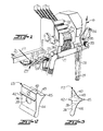
- the corespun yarn 10 includes a core 11 of fibers extending primarily in the axial or longitudinal direction, a core wrapper 12 of fibers surrounding and covering the core 11 and extending primarily in an axial direction, and an outer sheath 13 of fibers surrounding and covering the core wrapper 12 and extending primarily in a circumferential direction.
- the fibers of the core 11 and the core wrapper 12 enhance the tensile strength of the yarn while the fibers of the outer sheath 13 are located on the outer surface of the yarn and provide the desired appearance and general characteristics which are to be imparted to the corespun yarn 10.
- the corespun yarn 10 is produced on a DREF friction spinning apparatus which has been modified in accordance with the present invention, in the manner illustrated in Figures 1-3.
- the friction spinning apparatus includes a core and core wrapper drafting section having a succession of pairs of drafting or draw rolls 20, 21 and 22 with a modified type of entrance trumpet, broadly indicated at 23, positioned adjacent the nip of the first set of drafting rolls 20.
- Conventional trumpets 24 are positioned in the nips of the successive pairs of drafting rolls 21, 22.
- a set of delivery rolls 25 is provided at the exit end of the drafting section and operates to deliver and guide yarn into an elongated throat formed between a pair of perforated suction drums 26, 27 which are rotated in the same direction by a drive belt 28 and a drive pulley 29.
- a plurality of sheath fiber slivers 13 is guided downwardly into draw frame rolls 30, between carding drums 31 and then fed into the elongated throat formed between the pair of perforated suction drums 26, 27 to be wrapped around the outer surface of the yarn.
- the yarn leaves the exit end of the elongated throat between the pair of perforated drums 26, 27, it passes between withdrawing rolls 33 and is directed over and under yarn guides 34, 35 and to the conventional take-up mechanism of the apparatus, not shown.
- the modified entrance yarn trumpet 23 includes a planar, vertically extending, entrance face 36, a lower yarn guide passageway 39 through which the core wrapper sliver 12 is directed, and an upper yarn guide passageway 40 through which the yarn core roving 11 is directed.
- the planar front or entrance face 36 of the entrance trumpet 23 is provided with an integrally formed and outwardly extending horizontal guide rib or bar 42 which serves to maintain separation of the fibers of the core roving 11 and the core wrapper sliver 12 as they move into the entrance ends of the respective guide passageways 40, 39 of the entrance trumpet 23.
- the exit end of the trumpet 23 is provided with inwardly curving converging surfaces 43, 44 conforming substantially to the configuration of the peripheral surfaces of the first pair of draw rolls 20.
- the inwardly curving surfaces 43, 44 are joined together at an outwardly extending apex 45 which is positioned adjacent the nip of the pair of draw rolls 20.
- the forward or entrance ends of the guide passageways 39, 40 are vertically aligned and spaced apart below and above the guide rib 42.
- the exit end of the guide passageway 40 is positioned above and adjacent the exit end of the lower guide passageway 39 so that the core roving 11 is positioned on top of and in the center of the core wrapper sliver 12 as they pass between the nip of the first set of drafting rolls 20.
- the fibers are drawn as they pass through the succession of drafting rolls 20, 21 and 22 of the drafting section and the core wrapper sliver 12 surrounds the fibers of the core 11.
- the fibers of the outer sheath 13 are wrapped around the same in a substantially circumferential direction so that the outer sheath 13 completely surrounds and covers the core wrapper 12 and the core 11.
- the corespun yarn 10 is then removed through the exit end of the friction spinning section by the withdrawing rolls 33 and is directed onto the take-up package, not shown.
- a wide variety of different types of fibers may be utilized to form the core 11, the core wrapper 12, and the outer sheath 13. It has been found that a particularly useful three component corespun yarn can be formed on the friction spinning apparatus of the present invention by feeding a core roving 11 of high temperature resistant fibers into the upper guide passageway 40 of the trumpet 23, feeding a core wrapper sliver 12 of low temperature resistant fibers into the lower guide passageway 39, and feeding a plurality of slivers of low temperature resistant fibers 13 into the draw frame rolls 30. This three component corespun yarn is then woven or knit to form a fabric which is highly useful in the production of fire resistant safety apparel.
- a very effective fire resistant fabric has been formed in accordance with the following nonlimiting example.
- a core roving 11 comprising 40% PBI fibers and 60% Kevlar fibers, and having a weight necessary to achieve 20% in overall yarn weight, is fed into the upper guide passageway 40 of the entrance trumpet 23.
- a core wrapper sliver 12 comprising 100% cotton staple fibers, and having a weight necessary to achieve 30% in overall yarn weight, is fed through the lower guide passageway 39 in the entrance trumpet 23.
- a plurality of outer sheath slivers 13, comprised entirely of cotton fibers, is fed into the draw frame rollers 30 and in an amount sufficient to achieve 50% in overall yarn weight.
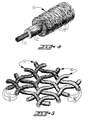
- the resulting corespun yarn 10 is woven into both the warp and filling to form a 155,9 g (5.5 ounce) plain weave fabric, of the type illustrated in Figure 2.
- This woven fabric is dyed and subjected to a topical fire resistant chemical treatment, and a conventional durable press resin finish is then applied thereto.
- the resulting fabric exhibits durable press ratings of 3.0+ after one wash, and 3.0 after five washes. This fabric also exhibits colorfastness when subjected to a carbon arc light source of a 4-5 rating at 40 hours exposure.
- NFPA 701 National Fire Prevention Association test method
- NFPA 701 National Fire Prevention Association test method
- a vertical burn of two 12 second exposures to a high heat flux butane flame shows 22% consumption with zero seconds afterflame, as compared with 45% consumption and 6 seconds afterflame for a 100% Nomex III fabric of similar weight and construction.
- Hot air shrinkage of the corespun fabric was tested in a heated chamber at 242,2°C (468° F.) for five minutes and shrinkage was less than 1% in both warp and filling direction.
- the areas of the fabric char remain flexible and intact, exhibiting no brittleness, melting, or fabric shrinkage.
- the portion of the fabric illustrated in the right-hand portion of Figure 2 is speckled to indicate an area which has been subjected to a burn test and to illustrate the manner in which the low temperature resistant fibers become charred but remain in position surrounding the core of high temperature resistant fibers.
- the charred fibers of the outer sheath 13 and the core wrapper 12 remaining in position around the core 11 provide a thermal insulation barrier and insulating air layer between the skin and the fabric, when the fabric is utilized to form a firefighter's shirt or the like.
- friction spinning apparatus and method of the present invention are not limited to the production of yarn and fabric useful in the production of fire resistant safety apparel of the type set forth above but may be utilized in producing a wide variety of different types of three component corespun yarns, useful in the formation of a wide variety of different types of fabrics.
- the three component corespun yarns produced by the friction spinning apparatus of the present invention each includes a core 11 with the fibers extending primarily in an axial or longitudinal direction of the yarn, a core wrapper 12 of fibers surrounding and covering the core 11 and with the fibers extending primarily in the axial or longitudinal direction of the yarn, and an outer sheath 13 of fibers surrounding and covering the core wrapper 12 and with these fibers extending primarily in a circumferential direction around the corespun yarn 10.
- the feeding of the additional fibers to the friction spinning apparatus is made possible by the provision of an entrance trumpet which includes a pair of guide passageways for directing and maintaining the core fibers and the core wrapper fibers in the proper relationship as they are directed through the drafting section of the friction spinning apparatus.
Landscapes
- Engineering & Computer Science (AREA)
- Mechanical Engineering (AREA)
- Textile Engineering (AREA)
- Spinning Or Twisting Of Yarns (AREA)
- Yarns And Mechanical Finishing Of Yarns Or Ropes (AREA)
- Spinning Methods And Devices For Manufacturing Artificial Fibers (AREA)
Claims (6)
- Friktions-Spinnvorrichtung zum Herstellen eines Kerngarnes, mit einem Paar benachbarter, drehbarer Saugtrommeln 26, 27, die einen engen Durchlaß von überwiegender Längserstrekkung begrenzen, der sich zwischen den Saugtrommeln 26, 27 erstreckt und Ein- und Auslaufenden aufweist, eine Strecke 20, 21, 22, 25 mit Ein- und Auslaufenden und bei der das Auslaufende 25 in der Nähe des Einlaufendes des sich zwischen den Saugtrommeln 26, 27 erstreckenden engen Durchlasses von überwiegender Längserstreckung angeordnet ist, eine Trichter einrichtung 23, die in der Nähe des Einlaufendes der Strecke 20, 21, 22, 25 angeordnet ist und einen ersten Führungskanal 39 zum Einführen eines Faserbandes 12 in die Strecke 20, 21, 22, 25 aufweist, eine Garnabnahmeeinrichtung 33, die in der Nähe des Auslaufendes des engen Durchlasses von überwiegender Längserstreckung angeordnet ist, und eine Walzenstrecke 30, 31 mit Ein- und Auslaufenden, die in der Nähe des engen Durchlasses von überwiegender Längserstreckung angeordnet ist und Faserbänder 13 in ihrem Einlaufende zu empfangen und gestreckte Umhüllungsfasern 13 in den engen Durchlaß von überwiegender Längserstreckung zuzuführen vermag, derart, daß die Umhüllungsfasern 13 um die sich entlang dem engen Durchlaß von überwiegender Längserstreckung erstreckenden Fasern ge wickelt werden, gekennzeichnet durch eine Einrichtung zum Zuführen eines zusätzlichen Faserbandes 11 in die Strecke 20, 21, 22, 25 zur Herstellung eines Dreifach-Kerngarns 10, wobei die Einrichtung zum Zuführen zusätzlicher Fasern einen zusätzlichen Bandführungskanal 40 in der Trichtereinrichtung 23 aufweist und in der Nähe des ersten Bandführungskanals 39 zum Lenken des zusätzlichen Bandes 11 in den Mittelteil des durch den ersten Bandführungskanal 39 der Trichtereinrichtung 23 hindurchlaufenden Bandes 12, derart, daß das erste Band und das zusätzliche Band durch die Strecke 20, 21, 22, 25 hindurchlaufen und in ihr bei Umhüllung des zusätzlichen Bandes 11 durch das erste Band 12 gestreckt werden, und wobei die Fasern 13 von der Walzenstrecke 30, 31 um das erste Band 12 und das zusätzliche Band 11, die durch den engen Durchlaß von überwiegender Längserstreckung hindurchlaufen, in der Weise gewickelt werden, daß das Dreifach-Kerngarn 10 entsteht.
- Friktions-Spinnvorrichtung nach Anspruch 1, dadurch gekennzeichnet, daß die Trichtereinrichtung 23 eine ebene Eintrittsstirnfläche 36 und ein Auslaufende aufweist, das Auslaufende ein Paar nach innen gekrümmter Flächen 43, 44 auf weist, die an einem nach außen sich erstreckenden Scheitel 45 miteinander verbunden sind, der erste Führungskanal 39 und der zusätzliche Führungskanal 40 in der Trichtereinrichtung 23 je ein Einlaufende in der ebenen Eintrittsstirnfläche 36 und ein Auslaufende in der Nähe des sich nach außen erstrekkenden Scheitels 45 aufweisen, und bei der die Einlaufenden auf der ebenen Eintrittsstirnfläche 36 mit Zwischenabstand und in senkrechter Ausrichtung angeordnet sind.
- Friktions-Spinnvorrichtung nach Anspruch 2, dadurch gekennzeichnet, daß die Auslaufenden des ersten Führungskanals 39 und des zusätzlichen Führungskanals 40 nahe aneinander an dem nach außen sich erstreckenden Scheitel 45 der Trichtereinrichtung 23 angeordnet sind.
- Friktions-Spinnvorrichtung nach Anspruch 3, dadurch gekennzeichnet, daß die ebene Eintrittsstirnfläche 36 der Trichtereinrichtung 23 eine sich waagerecht erstreckende Führungsrippe 42 aufweist, die aus der ebenen Eintrittsstirnfläche 36 und zwischen den beabstandeten Einlaufenden des ersten Führungskanals 39 und des zusätzlichen Führungskanals 40 in der Weise herausragt, daß sie zur Getrennthaltung der Fasern der in und durch die Führungskanäle 39, 40 geführten Bänder beiträgt.
- Friktions-Spinnvorrichtung nach einem der Ansprüche 2 bis 4, dadurch gekennzeichnet, daß die Strecke 20, 21, 22, 25 aufeinanderfolgende Paare von Streckwalzen aufweist, die zwischen sich Einzugspalte begrenzen, und bei der die nach innen gekrümmten Flächen 43, 44 des Auslaufendes der Trichtereinrichtung 23 im wesentlichen an die Umfangsflächen des ersten Paares (20) Streckwalzen angepaßt sind, und der nach außen sich erstreckende Scheitel 45 der Trichtereinrichtung 23 in der Nähe des Einzugspaltes des ersten Paares (20) Streckwalzen angeordnet ist.
- Verfahren zum Friktionsspinnen eines Dreifach-Kerngarnes, mit dem getrennten Führen eines ersten und eines zweiten Bandes Fasern über Führungskanäle zu einer Strecke, und beim Strek ken Zusammenführen der Bänder in der Strecke, damit die er sten Bänder die zweiten Bänder umhüllen und danach die gestreckten Bänder mit Umhüllungsfasern umwickelt werden.
Priority Applications (1)
| Application Number | Priority Date | Filing Date | Title |
|---|---|---|---|
| AT89309152T ATE89042T1 (de) | 1988-12-22 | 1989-09-08 | Friktions-spinnvorrichtung und verfahren zur herstellung von kerngarn. |
Applications Claiming Priority (2)
| Application Number | Priority Date | Filing Date | Title |
|---|---|---|---|
| US288767 | 1988-12-22 | ||
| US07/288,767 US4860530A (en) | 1988-12-22 | 1988-12-22 | Corespun yarn friction spinning apparatus and method |
Publications (3)
| Publication Number | Publication Date |
|---|---|
| EP0375112A2 EP0375112A2 (de) | 1990-06-27 |
| EP0375112A3 EP0375112A3 (en) | 1990-12-05 |
| EP0375112B1 true EP0375112B1 (de) | 1993-05-05 |
Family
ID=23108554
Family Applications (1)
| Application Number | Title | Priority Date | Filing Date |
|---|---|---|---|
| EP89309152A Expired - Lifetime EP0375112B1 (de) | 1988-12-22 | 1989-09-08 | Friktions-Spinnvorrichtung und Verfahren zur Herstellung von Kerngarn |
Country Status (9)
| Country | Link |
|---|---|
| US (1) | US4860530A (de) |
| EP (1) | EP0375112B1 (de) |
| JP (1) | JPH0684569B2 (de) |
| KR (1) | KR930008380B1 (de) |
| CN (1) | CN1020769C (de) |
| AT (1) | ATE89042T1 (de) |
| AU (1) | AU618918B2 (de) |
| CA (1) | CA1319573C (de) |
| DE (1) | DE68906369D1 (de) |
Families Citing this family (16)
| Publication number | Priority date | Publication date | Assignee | Title |
|---|---|---|---|---|
| US5033262A (en) * | 1988-12-22 | 1991-07-23 | Springs Industries, Inc. | Method of forming a corespun yarn for fire resistant safety apparel |
| CA2044378A1 (en) * | 1990-10-02 | 1992-04-03 | Mitsuo Matsumoto | Shock-absorbing air bag |
| US5802826A (en) * | 1993-08-06 | 1998-09-08 | The United States Of America As Represented By The Secretary Of Agriculture | Production of core/wrap yarns by airjet and friction spinning in tandem |
| DE19601038A1 (de) * | 1996-01-13 | 1997-07-17 | Fritz Stahlecker | Verfahren zum Offenend-Spinnen |
| GB9806622D0 (en) * | 1998-03-30 | 1998-05-27 | Univ Leeds | Friction spinning machine |
| US6637085B2 (en) * | 2001-10-26 | 2003-10-28 | E. I. Du Pont De Nemours And Company | Process for recycling articles containing high-performance fiber |
| ES2413780T3 (es) * | 2005-10-17 | 2013-07-17 | Welspun Uk Limited | Materiales higroscópicos para su utilización en la fabricación de hilos y tejidos |
| CN102011228B (zh) * | 2010-11-05 | 2013-01-02 | 广州纺织服装研究院 | 一种粗纱须条花式线及其纺纱装置和纺纱方法 |
| CN102021683A (zh) * | 2010-12-30 | 2011-04-20 | 山东宏业纺织股份有限公司 | 粗纱机及利用其进行赛络纺的加工方法 |
| CN104762704B (zh) * | 2015-03-19 | 2017-09-15 | 上海工程技术大学 | 一种新型纳米级静电摩擦纺纱装置 |
| CN105220246B (zh) * | 2015-08-31 | 2017-11-24 | 中原工学院 | 一种静电纺纳米纤维的多股喷气摩擦成纱装置及制备方法 |
| US9828704B2 (en) | 2015-09-10 | 2017-11-28 | Welspun India Limited | Terry article with synthetic filament yarns and method of making same |
| CA3127604A1 (en) * | 2019-01-22 | 2020-07-30 | Mpusa, Llc | Dual functional spun + filament fiber woven terry cooling towel |
| CN114908451B (zh) * | 2022-02-23 | 2024-03-22 | 江苏工程职业技术学院 | 基于并条工序的短纤维纱芯环锭包芯纱的纺纱方法 |
| CN117552132A (zh) * | 2023-12-21 | 2024-02-13 | 无锡舟控客电子设备有限公司 | 一种蓬绒纱纺纱设备 |
| CN117802639A (zh) * | 2024-01-03 | 2024-04-02 | 东台市华源复合材料有限公司 | 一种用于包芯纱加工的空气摩擦纺纱机 |
Family Cites Families (9)
| Publication number | Priority date | Publication date | Assignee | Title |
|---|---|---|---|---|
| US3092953A (en) * | 1960-08-01 | 1963-06-11 | Bear Brand Hosiery Co | Method and apparatus for forming yarn |
| US3370410A (en) * | 1965-01-29 | 1968-02-27 | Caron Spinning Company | Spinning device |
| US4041690A (en) * | 1975-11-05 | 1977-08-16 | Tuscarora Cotton Mill | Novelty yarn and method for making same |
| AT339779B (de) * | 1976-04-08 | 1977-11-10 | Fehrer Ernst Gmbh | Vorrichtung zum spinnen textiler fasern |
| DE2909615C2 (de) * | 1978-05-26 | 1982-03-18 | Ernst Dr. 4020 Linz Fehrer | Vorrichtung zum Herstellen eines Garnes |
| DE3023936A1 (de) * | 1979-07-27 | 1981-02-19 | Ernst Dr Fehrer | Vorrichtung zum herstellen eines garnes |
| AT381510B (de) * | 1985-04-23 | 1986-10-27 | Fehrer Ernst | Vorrichtung zum herstellen eines garnes |
| US4711079A (en) * | 1986-01-31 | 1987-12-08 | Burlington Industries, Inc. | Roving blending for making sheath/core spun yarn |
| AT384039B (de) * | 1986-03-07 | 1987-09-25 | Fehrer Ernst | Vorrichtung zum herstellen eines garnes |
-
1988
- 1988-12-22 US US07/288,767 patent/US4860530A/en not_active Expired - Lifetime
-
1989
- 1989-09-08 EP EP89309152A patent/EP0375112B1/de not_active Expired - Lifetime
- 1989-09-08 DE DE8989309152T patent/DE68906369D1/de not_active Expired - Lifetime
- 1989-09-08 AT AT89309152T patent/ATE89042T1/de not_active IP Right Cessation
- 1989-09-14 AU AU41315/89A patent/AU618918B2/en not_active Ceased
- 1989-09-14 CA CA000611362A patent/CA1319573C/en not_active Expired - Fee Related
- 1989-10-16 JP JP1266363A patent/JPH0684569B2/ja not_active Expired - Fee Related
- 1989-12-22 KR KR1019890019329A patent/KR930008380B1/ko not_active Expired - Fee Related
- 1989-12-22 CN CN89109810A patent/CN1020769C/zh not_active Expired - Fee Related
Also Published As
| Publication number | Publication date |
|---|---|
| JPH02175928A (ja) | 1990-07-09 |
| AU618918B2 (en) | 1992-01-09 |
| CN1044834A (zh) | 1990-08-22 |
| ATE89042T1 (de) | 1993-05-15 |
| EP0375112A3 (en) | 1990-12-05 |
| US4860530A (en) | 1989-08-29 |
| EP0375112A2 (de) | 1990-06-27 |
| KR900010096A (ko) | 1990-07-06 |
| AU4131589A (en) | 1990-06-28 |
| DE68906369D1 (de) | 1993-06-09 |
| KR930008380B1 (ko) | 1993-08-31 |
| CA1319573C (en) | 1993-06-29 |
| CN1020769C (zh) | 1993-05-19 |
| JPH0684569B2 (ja) | 1994-10-26 |
Similar Documents
| Publication | Publication Date | Title |
|---|---|---|
| US4958485A (en) | Corespun yarn for fire resistant safety apparel | |
| US5033262A (en) | Method of forming a corespun yarn for fire resistant safety apparel | |
| EP0375112B1 (de) | Friktions-Spinnvorrichtung und Verfahren zur Herstellung von Kerngarn | |
| US5572860A (en) | Fusible adhesive yarn | |
| US2132702A (en) | Combined asbestos and glass fiber yarn | |
| EP0745151A1 (de) | Umwindegarn | |
| US4711079A (en) | Roving blending for making sheath/core spun yarn | |
| JP7286122B2 (ja) | 紡績糸及びその製造方法 | |
| CA1062564A (en) | Method of making core yarn | |
| KR101334886B1 (ko) | 신축성과 피복율이 우수한 코어얀, 그 제조방법 및 제조장치 | |
| RU2402649C1 (ru) | Термостойкая швейная нитка и способ ее получения | |
| KR102403772B1 (ko) | 난연성이 우수한 모다크릴/텐셀 에어젯트 혼합방적사의 제조방법 | |
| JPH0978379A (ja) | 芯鞘型複合紡績糸およびそれを用いた編織物 | |
| JPS6331568B2 (de) | ||
| JPS63227820A (ja) | 耐炎・耐熱複合紡績糸の製造方法 | |
| JPH10280239A (ja) | 複合紡績糸およびその製造方法ならびに布帛 | |
| JPH0635689B2 (ja) | 複合糸の製造方法 | |
| CN117265727A (zh) | 一种包芯纱及其制备方法、针织呢绒面料的制备方法 | |
| JP3502483B2 (ja) | 仮撚り複合糸の製造方法 | |
| JPS5847486B2 (ja) | 特殊嵩高糸の製造方法 | |
| JPS62162038A (ja) | ポリアミド被覆弾性糸およびその製造方法 | |
| CN117693616A (zh) | 多层结构短纤维纱、其制造方法、耐热性布帛及耐热性防护服 | |
| GB2080847A (en) | Unspun yarn | |
| JPH055225A (ja) | 繊維束の牽切方法 | |
| JPH03193929A (ja) | 複合紡績糸の製造方法 |
Legal Events
| Date | Code | Title | Description |
|---|---|---|---|
| PUAI | Public reference made under article 153(3) epc to a published international application that has entered the european phase |
Free format text: ORIGINAL CODE: 0009012 |
|
| AK | Designated contracting states |
Kind code of ref document: A2 Designated state(s): AT BE CH DE ES FR GB GR IT LI LU NL SE |
|
| PUAL | Search report despatched |
Free format text: ORIGINAL CODE: 0009013 |
|
| AK | Designated contracting states |
Kind code of ref document: A3 Designated state(s): AT BE CH DE ES FR GB GR IT LI LU NL SE |
|
| 17P | Request for examination filed |
Effective date: 19901116 |
|
| 17Q | First examination report despatched |
Effective date: 19920623 |
|
| GRAA | (expected) grant |
Free format text: ORIGINAL CODE: 0009210 |
|
| AK | Designated contracting states |
Kind code of ref document: B1 Designated state(s): AT BE CH DE ES FR GB GR IT LI LU NL SE |
|
| PG25 | Lapsed in a contracting state [announced via postgrant information from national office to epo] |
Ref country code: IT Free format text: LAPSE BECAUSE OF FAILURE TO SUBMIT A TRANSLATION OF THE DESCRIPTION OR TO PAY THE FEE WITHIN THE PRE;WARNING: LAPSES OF ITALIAN PATENTS WITH EFFECTIVE DATE BEFORE 2007 MAY HAVE OCCURRED AT ANY TIME BEFORE 2007. THE CORRECT EFFECTIVE DATE MAY BE DIFFERENT FROM THE ONE RECORDED.SCRIBED TIME-LIMIT Effective date: 19930505 Ref country code: LI Effective date: 19930505 Ref country code: FR Effective date: 19930505 Ref country code: AT Effective date: 19930505 Ref country code: NL Effective date: 19930505 Ref country code: SE Effective date: 19930505 Ref country code: BE Effective date: 19930505 Ref country code: CH Effective date: 19930505 Ref country code: GR Free format text: LAPSE BECAUSE OF FAILURE TO SUBMIT A TRANSLATION OF THE DESCRIPTION OR TO PAY THE FEE WITHIN THE PRESCRIBED TIME-LIMIT Effective date: 19930505 Ref country code: DE Effective date: 19930505 Ref country code: ES Free format text: THE PATENT HAS BEEN ANNULLED BY A DECISION OF A NATIONAL AUTHORITY Effective date: 19930505 |
|
| REF | Corresponds to: |
Ref document number: 89042 Country of ref document: AT Date of ref document: 19930515 Kind code of ref document: T |
|
| REF | Corresponds to: |
Ref document number: 68906369 Country of ref document: DE Date of ref document: 19930609 |
|
| REG | Reference to a national code |
Ref country code: CH Ref legal event code: PL |
|
| PG25 | Lapsed in a contracting state [announced via postgrant information from national office to epo] |
Ref country code: GB Effective date: 19930908 |
|
| EN | Fr: translation not filed | ||
| PG25 | Lapsed in a contracting state [announced via postgrant information from national office to epo] |
Ref country code: LU Free format text: LAPSE BECAUSE OF NON-PAYMENT OF DUE FEES Effective date: 19930930 |
|
| NLV1 | Nl: lapsed or annulled due to failure to fulfill the requirements of art. 29p and 29m of the patents act | ||
| PLBE | No opposition filed within time limit |
Free format text: ORIGINAL CODE: 0009261 |
|
| STAA | Information on the status of an ep patent application or granted ep patent |
Free format text: STATUS: NO OPPOSITION FILED WITHIN TIME LIMIT |
|
| 26N | No opposition filed | ||
| GBPC | Gb: european patent ceased through non-payment of renewal fee |
Effective date: 19930908 |